
Chapter 10: IoT Plant Pot Moisture Sensor
With the advent of the Internet of Things (IoT), we are immersed in the new industrial revolution—the so-called Industry 4.0. One of the industries that have benefited the most from these technologies is agriculture (Chalimov, 2020). Agricultural IoT applications range from autonomous harvesting to sensors to recognize pests and diseases or to measure humidity. We can take advantage of these advances in our homes—for instance, monitoring our ornamental plants to have more efficient care.
In this chapter, you will put into practice information learned in Chapter 9, IoT Temperature-Logging System, about how to connect and program an internet connection, but this time we will introduce a NodeMCU microcontroller to facilitate the ESP8266 programming. You will learn how to create a digital device to monitor a plant pot, reading data from a soil moisture sensor and determining whether it needs water, and then sending an alert to notify that it is too dry.
In this chapter, we will cover the following main topics:
- Connecting a soil moisture sensor to the Blue Pill board
- Reading data from the soil moisture sensor module
- Coding a program to send the sensed data to the internet
- Showing sensor data results over the internet
By completing this chapter, you will discover how to read the soil's moisture amount through a sensor connected to the STM32 Blue Pill board. You will also learn how to send this information to the internet through the NodeMCU development board and visualize the sensor values from a responsive web page.
Technical requirements
The hardware components that will be needed to develop the plant pot moisture system are listed as follows:
- One solderless breadboard.
- One Blue Pill microcontroller board.
- One NodeMCU microcontroller.
- One ST-Link/V2 electronic interface, needed for uploading the compiled code to the Blue Pill board. Bear in mind that the ST-Link/V2 interface requires four female-to-female jumper wires.
- One soil moisture sensor.
- One ESP8266 Wi-Fi module.
- Male-to-male jumper wires.
- Power source.
These components can be easily obtained from your favorite supplier. Additionally, you will require the Arduino integrated development environment (IDE) and the GitHub repository for this chapter, which can be found at https://github.com/PacktPublishing/DIY-Microcontroller-Projects-for-Hobbyists/tree/master/Chapter10
The Code in Action video for this chapter can be found here: https://bit.ly/3d9CmNM
The next section presents an introduction to a soil moisture sensor and how to use it with the STM32 Blue Pill microcontroller board.
Connecting a soil moisture sensor to the Blue Pill board
We will start this section by learning how to use a sensor to measure soil humidity in a plant pot, and you will later learn how to connect it to the STM32 Blue Pill board to build a plant pot moisture-monitoring system.
Introducing soil moisture sensors
A soil moisture sensor consists of two pads that measure the amount of water in the soil. The sensed value is acquired by allowing the the electric current running through the soil to pass through, and according to resistance, this shows the level of humidity in the plant pot.
You can find a generic breakout module that is pretty straightforward to use. This is shown in the following photo:
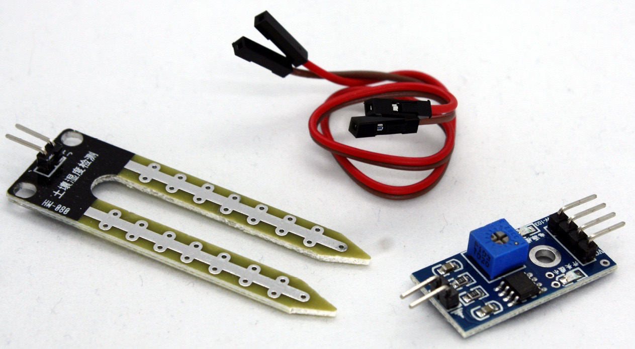
Figure 10.1 – Soil moisture sensor breakout board
The pads are connected to the breakout board with the included female-to-female jumper wires. The breakout board connects to the STM32 Blue Pill board with four pins, outlined as follows:
- Analog output (AO): This pin generates an analog signal and must be connected to an analog input of the microcontroller.
- Digital output (DO): This pin generates a digital signal and must be connected to a digital input of the microcontroller.
- VCC: Pin to supply power to the sensor (3.3 volts (V)-5 V).
- Ground (GND): Ground connection.
To simplify the development of our project, we will use a DO pin to build our system because it only generates binary data depending on the humidity.
Connecting the components
We will use a solderless breadboard to connect the sensor and the STM32 Blue Pill microcontroller, and finally wire to connect the components. Follow these steps:
- Place the soil moisture sensor and the STM32 Blue Pill board on the solderless breadboard with enough space to add the wiring layer.
- Connect the ground (GND) pin of the sensor to a GND terminal of the SMT32 Blue Pill board.
- Next, you need to connect the voltage (VCC) pin to the 3V3 bus of the STM32 Blue Pill board. The sensor DO must be connected to a digital input on the STM32 Blue Pill board, so connect the DO pin of the sensor to pin B12 of the Blue Pill, as shown in the following photo:

Figure 10.2 – Soil moisture sensor connection to the Blue Pill
- Finally, you will need a power source to power up the board. Use the ST-LINK to upload the scripts to the STM32 Blue Pill microcontroller board. The following screenshot summarizes all the hardware connections:
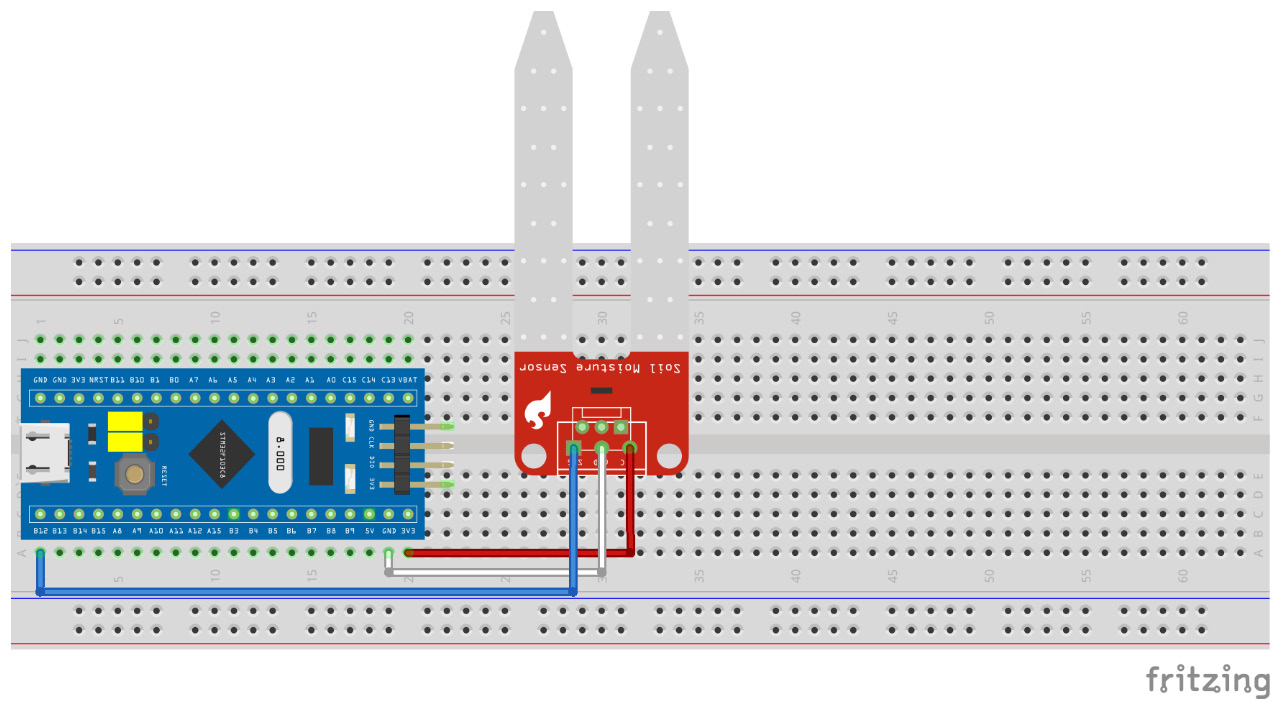
Figure 10.3 – Circuit for soil moisture sensor connection
The following screenshot presents a schematic diagram for this project:

Figure 10.4 – Schematic diagram for soil moisture sensor connection
Figure 10.4 shows an electric diagram for this part of the project. The ground pin of the sensor was connected to the GND pin of the Blue Pill, while the VCC pin was connected to the Blue Pill's 3V3 bus. Finally, the DO of the sensor was plugged into the B12 pin of the STM32 microcontroller. The following photo shows the plant pot moisture system:

Figure 10.5 – Plant pot moisture system
In the previous photo, we can see how the humidity monitoring system's deployment is carried out. As we can see, we built a compact electronic circuit to monitor the moisture of the soil in a plant pot.
In this section, we understood the concept of a humidity sensor and its components. Furthermore, we learned how to connect the sensor to a microcontroller through a breadboard, and finally learned how to connect the complete system to a plant pot.
It's time to move on to the next section, which will show you how to write C code to complete the IoT humidity monitoring system's first functionality.
Reading data from the soil moisture sensor module
You will now learn how to code a program that reads the information from the moisture sensor and shows on the serial monitor if the plant pot needs watering or is moist enough.
Let's start developing the program to collect the sensor data from the STM32 Blue Pill, as follows:
- Let's get started writing the code. This time, we won't need any additional libraries. Define which of the STM32 Blue Pill card pins will be used as input for reading the sensor data. Also, declare a variable to save the reading data from the sensor, as follows:
const int sensorPin = PB12;
int sensorValue = 0;
The input pin will be the PB12 pin (labeled B12 on the Blue Pill). Also, we initialize the sensorValue variable to a value of 0.
- Next, in the setup() part, we need to start the serial data transmission and assign the speed of the transfer (as usual, we will use 9,600 bits per second (bps) as the standard value). Here is the code to do this:
void setup() {
Serial.begin(9600);
}
- Indicate to the microcontroller the type of pin assigned to PB12 by running the following code:
void setup() {
Serial.begin(9600);
pinMode(sensorPin, INPUT);
}
- The rest of the sketch is in the loop() part. The first lines read the input pin's data sensor and display its value in the serial console. The code is shown in the following snippet:
void loop() {
sensorValue = digitalRead(sensorPin);
Serial.print("Sensor value: ");
Serial.println(sensorValue);
if (sensorValue == 1) {
Serial.println("Soil is too dry");
delay(1000);
} else {
Serial.println("Soil is moist enough");
delay(1000);
}
}
The value read from the sensor could be 1 or 0; remember, we are reading a digital value. If the value is 1, then the plant pot needs water; otherwise, it is moist enough.
The code is now complete. You can find the complete sketch in the Chapter10/moisture folder in the GitHub repository.
- Now that the sketch is complete, you can upload it to the Blue Pill board and insert the sensor pads into a plant pot. Now, you can see in the serial monitor that the soil is too dry, as shown in the following screenshot:
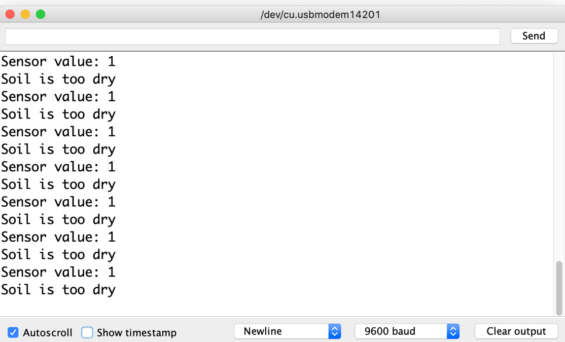
Figure 10.6 – Serial monitor readings with dry soil
- Now, add water to the plant pot, taking care not to get any electronic components wet. The serial monitor's information will change as soon as the soil gets wet, as illustrated in the following screenshot:
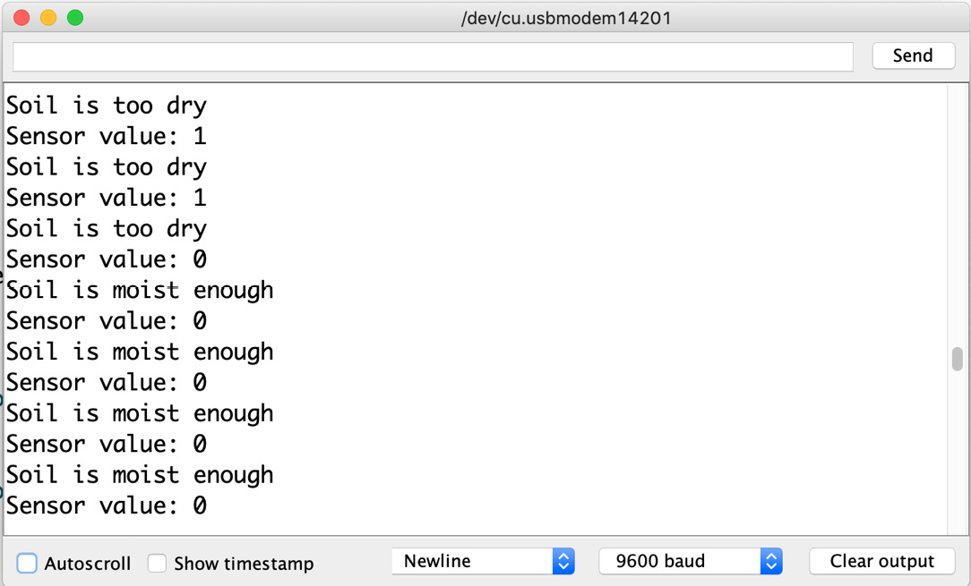
Figure 10.7 – Serial monitor readings upon moistening the soil
Important note
In recent macOS versions, the Universal Serial Bus (USB) port may not appear in the Arduino IDE, and it therefore may not be possible to see the serial monitor. To solve this, it is necessary to install the USB-UART drivers (where UART stands for Universal Asynchronous Receiver/Transmitter) from https://www.silabs.com/developers/usb-to-uart-bridge-vcp-drivers.
Let's recap what we have learned so far. We learned about a sensor to measure soil humidity. We learned how to connect it to our STM32 Blue Pill microcontroller in the Connecting a soil moisture sensor to the Blue Pill board section. In this section, we wrote the code to obtain its data and display it on the serial monitor.
The skills you have acquired so far in this chapter will allow you to create other electronic systems that require digital reading of data generated in sensors, enabling you to use this sensor in additional projects where it is required to measure soil moisture.
Coming up next, we will learn about the NodeMCU microcontroller, which will facilitate connection to the internet with its integrated ESP8266 module.
Coding a program to send the sensed data to the internet
If you remember, in Chapter 9, IoT Temperature-Logging System, we found that an ESP-01 module was used because it integrates Wi-Fi communication through ESP8266. This module was programmed using AT commands through the STM32 Blue Pill microcontroller (where AT stands for Attention). As mentioned at the beginning of the chapter, we will use the NodeMCU development board, which is depicted in the following photo:
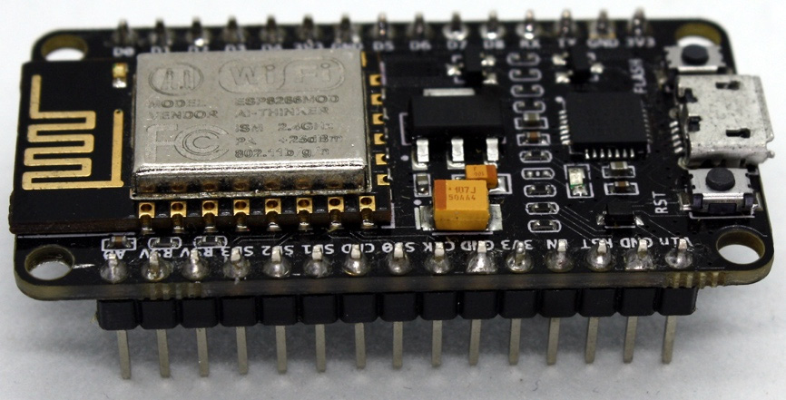
Figure 10.8 – NodeMCU development board
This board is also based on the ESP8266 microcontroller. However, unlike the SP-01 module, this can be programmed directly from its micro USB port using different development IDEs and various programming languages such as Lua and C. It also includes general-purpose input/output (GPIO) pins to be programmed according to the developer's needs. These characteristics make the NodeMCU microcontroller one of the most popular IoT platforms today.
The NodeMCU associates with both firmware and development boards, and in conjunction offers the most popular open source IoT platform. The development board is based on the ESP-12 module that, as with the ESP-01 module, gives us the Wi-Fi connection functionality and adds the functionality of the development board, with the following features:
- Micro USB port and serial-USB converter
- Simple programming via micro USB
- Power via USB terminals (pins) for easy connection
- Integrated reset button and light-emitting diode (LED)
Using its pins, we can easily place it on a solderless breadboard to connect the electronic components required by the projects we will carry out. The NodeMCU enables Wi-Fi communication using the Transmission Control Protocol/Internet Protocol (TCP/IP) stack.
Important note
To program the NodeMCU, the steps to add this type of board indicated in the Showing sensor data results over the internet section of Chapter 9, IoT Temperature-Logging System, must already have been carried out.
Let's create a program to connect the NodeMCU to the internet. Follow these steps:
- First, include the Wi-Fi library for the ESP8266. You will need two string-type variables for the Wi-Fi network's service set identifier (SSID) and password (don't forget to change these to your actual values). Also, define an input pin and default value to read the sensor data from the STM32. The possible values gathered from the sensor are listed as follows:
- 0: Moist
- 1: Dry
- 2: Without reading. Hardcoded here, not from the sensor
The code is illustrated in the following snippet:
#include <ESP8266WiFi.h>
const char* ssid = "Your_SSID";
const char* password = "Your_Password";
const int fromStm32Pin = 4;
int sensorValue = 2;
- We will create a web server to receive the sensor data. The server will be listening on port 80. Here is the code to do this:
WiFiServer server(80);
- In the setup() part, we need to start the serial data transmission and assign the speed of the transfer (this time, we will use 115,200 bps). The code is shown in the following snippet:
void setup() {
Serial.begin(115200);
}
- Indicate to the NodeMCU board the type of pin for reading the STM32, as follows:
void setup() {
Serial.begin(115200);
pinMode(fromStm32Pin, INPUT);
}
- The rest of the setup() part will configure the Wi-Fi network, and upon a successful connection will send the IP address to the serial monitor. The code can be seen here:
void setup() {
Serial.begin(115200);
pinMode(fromStm32Pin, INPUT);
Serial.print("Connecting to WiFi network: ");
Serial.println(ssid);
WiFi.begin(ssid, password);
while (WiFi.status() != WL_CONNECTED) {
delay(500);
Serial.print(".");
}
Serial.println("");
Serial.println("WiFi connected.");
Serial.println("IP address: ");
Serial.println(WiFi.localIP());
server.begin();}
The loop() part was built into three functionalities. First, start the web server. Then, read the sensor data from the STM32. Finally, display a responsive web app to visualize the sensor monitoring.
For the complete sketch, refer to the Chapter10/webserver folder in the GitHub repository.
- The web server will be listening for incoming connections from clients. After a client connects, we catch it on the if condition, as illustrated in the following code snippet:
void loop() {
WiFiClient client = server.available();
if (client) {
// Code to serve the responsive webapp.
}
}
- After a client connects, the code verifies that is receiving a GET request with a command to read the sensor data, as illustrated in the following code snippet:
void loop() {
WiFiClient client = server.available();
if (client) {
if (header.indexOf("GET /4/read") >= 0) {
Serial.println("Reading the sensor");
sensorValue = digitalRead(fromStm32Pin);
}
}
}
- If the request received by the client asks the sensor value, the NodeMCU will take from the STM32 Blue Pill a reading of the sensor.
To make this bridge between the NodeMCU and the STM32, it will be necessary to add the additional connections shown in the following screenshot:
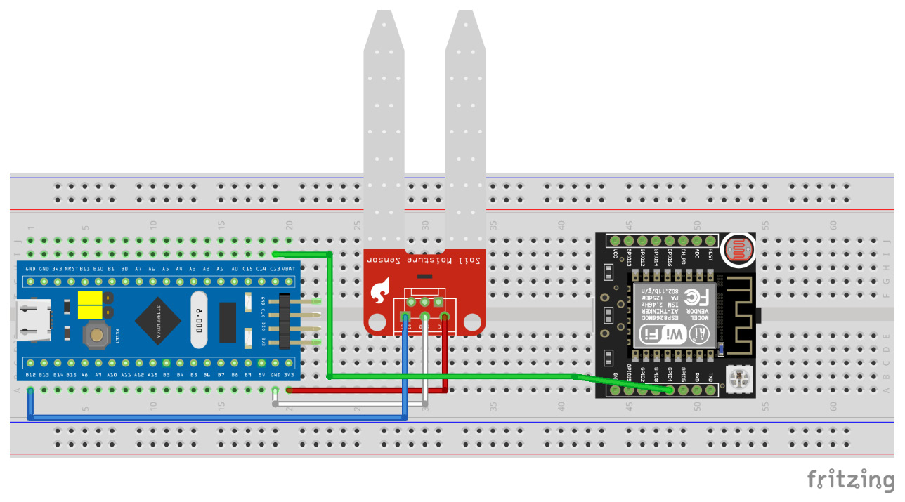
Figure 10.9 – Circuit for microcontrollers' interconnection
Here is a schematic diagram of the microcontrollers' interconnection:

Figure 10.10 – Schematic diagram of microcontrollers' interconnection
Connect a male-to-male jumper wire from NodeMCU GPIO 4 (D2) to the GPIO PC13 pin of the STM32.
The following photo shows how everything was connected in the actual system:

Figure 10.11 – STM32 and NodeMCU connection
- Now, to complete the connection between the NodeMCU and the STM32, it's necessary to add a few new lines of code to the Chapter10/moisture sketch.
Add a new constant to store the output pin used to send the data to the NodeMCU, as follows:
const int sensorPin = PB12;
int sensorValue = 0;
const int toInternetPin = PC13;
The output pin will be the PC13 pin (labeled C13 on the Blue Pill).
- In the setup() part, indicate the pin type for PC13, as follows:
void setup() {
Serial.begin(9600);
pinMode(sensorPin, INPUT);
pinMode(toInternetPin, OUTPUT);
}
- Modify the if condition in the loop() part, as follows:
void loop() {
if (sensorValue == 1) {
digitalWrite(toInternetPin, HIGH);
Serial.println("Soil is too dry");
delay(1000);
} else {
digitalWrite(toInternetPin, LOW);
Serial.println("Soil is moist enough");
delay(1000);
}}
With the preceding code, the STM32 Blue Pill will send the value 1 (HIGH) or 0 (LOW) according to the humidity sensor. Now, we can upload Chapter10/moisture to the STM32 and close the sketch and continue working in Chapter10/webserver.
- The final step to complete our web server is to serve a responsive web app after a client request. In this way, any device connected to the same Wi-Fi network and a web browser will be able to access the sensor reading remotely.
But first, we will learn a few concepts of HyperText Markup Language (HTML): the markup language to create a web page.
A basic structure of an HTML document could look like this:
<!DOCTYPE html>
<html>
<head>
<meta name="viewport" content="width=device-width, initial-scale=1">
<title>Page Title</title>
</head>
<body>
<h1>A heading</h1>
<p>A paragraph.</p>
<img src="anImage.jpg" >
<button>A button.</button>
</body>
</html>
As we build a responsive web app, it is essential to pay attention to the <meta> tag with the name property that has a viewport value. This tag will be responsible for adjusting our app's layout according to the device with which we are browsing, so we can do it from a desktop PC to a mobile device.
To give it the desired visual style, we can do it in two ways: importing a Cascading Style Sheets (CSS) file or including the styles within <style></style> tags, both within the <head> tag, as illustrated in the following code snippet:
<link rel="stylesheet" href="styleFile.css">
<style>Some styles</style>
For our web app, we are going to need a button. If we do not know much about giving CSS visual style, we can use tools freely available on the internet, such as https://www.bestcssbuttongenerator.com/, which will visually generate the style CSS of our buttons.
To include HTML code in our sketch, we will use the following sentence:
client.println("<html tags>");
The code for visualizing the sensor value on our web app prints a paragraph indicating to the user whether the soil is dry or not, and a graphical indicator to better understand our plant pot state, as illustrated in the following code snippet:
if (sensorValue == 1) {
client.println("<p>Soil is too dry</p>");
client.println("<p><img width="50" height="60" src="https://raw.githubusercontent.com/ PacktPublishing/Creative-DIY-Microcontroller- Projects/master/Chapter10/images/ dry_plant.png"></p>");
} else if (sensorValue == 0) {
client.println("<p>Soil is moist enough</p>");
client.println("<p><img width="50" height="60" src="https://raw.githubusercontent.com/ PacktPublishing/Creative-DIY-Microcontroller- Projects/master/Chapter10/images/ green_plant.png"></p>");
} else {
client.println("<p>Press the button to read the sensor</p>");
}
client.println("<p><a href="/4/read"> <button class="sensorButton"><i class="fas fa- satellite-dish"></i> Read sensor</button> </a></p>");
To allow the user to gather the sensor reading, we included a button to press each time they need to know their plant's status. Remember—the complete code for this part of the project is available in the Chapter10/webserver GitHub folder.
Important note
If you need to use free images and icons, you can find them on the internet repositories such as the following:
The sketch is now complete, so upload it to the NodeMCU board and reset it after completing the upload. Now, you can see in the serial monitor the IP address to connect our client, as shown in the following screenshot:
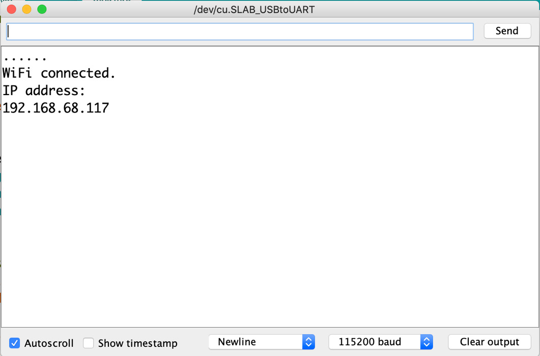
Figure 10.12 – IP address on the serial monitor
It's now time to move on to the next section, which will show you how to visualize the data over the internet.
Showing sensor data results over the internet
Having objects connected to the internet will allow you to access their data from anywhere that has a connection to that network.
This is why we gave our project the ability to become a web server and thus be able to access the state of the plant pot from any web browser.
For this project, access can only be from our Wi-Fi network. To test its operation, we are going to access the developed web app from any mobile or desktop web browser. Proceed as follows:
- Open a web browser and go to the IP address of our server (see Figure 10.12). You should see our landing page to monitor our plant pot, as shown in the following screenshot:
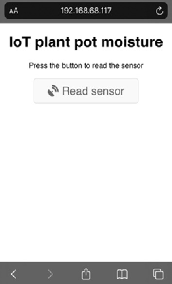
Figure 10.13 – Web app landing page
- On the landing page, you can simply press the button every time you want to measure the humidity of the plant pot. If the soil is dry, we will see a representative image and a legend stating Soil is too dry, as illustrated in the following screenshot:
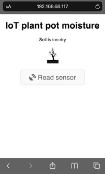
Figure 10.14 – Web app screen for dry soil
- Otherwise, if the soil has good humidity, we get a legend stating Soil is moist enough along with a representative image, as illustrated in the following screenshot:
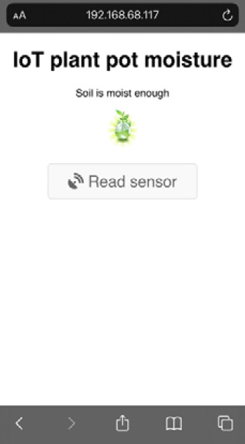
Figure 10.15 – Web app screen for moist soil
You can monitor your plant pots with this IoT device and application from anywhere in your home, as long as you are connected to your local Wi-Fi network.
We have reached the end of this chapter. Well done! Let's see what we learned in this project.
Summary
At the beginning of the project, you saw how to interface a soil moisture sensor to your STM32 board. Then, we created a simple sketch to collect the sensor readings and tested it to ensure it worked properly.
We also learned how to connect a NodeMCU card to the internet and read the sensor data from the STM32. Finally, in the last part of the project, we built a web app to control the IoT device from any web browser, either mobile or desktop.
The IoT area is growing quickly, so talented people with the right skills in this technology can easily access jobs in this exciting area. With this in mind, after completing this chapter, we now have a stronger foundation for creating IoT devices and applications.
In the next chapter, we will learn how to connect our electronic devices to the internet and make them available outside our local Wi-Fi network.
Further reading
Chalimov, A, IoT in agriculture: 8 technology use cases for smart farming (and challenges to consider). Eastern Peak, 2020: https://easternpeak.com/blog/iot-in-agriculture-technology-use-cases-for-smart-farming-and-challenges-to-consider/