
Chapter
6
iSCSI SAN
TOPICS COVERED IN THIS CHAPTER:
- iSCSI from 40,000 feet
- Initiators and targets
- iSCSI interfaces
- IP network considerations
- Discovery
- Login
- Sessions
- iSNS
- Security
- iSCSI gateways
 In this chapter, you'll explore the increasingly popular iSCSI SAN. This chapter first covers the major concepts and principles and then discusses some technologies that will help you build and manage iSCSI SANs of varying sizes and complexities. And as iSCSI SANS are built on top of IP networks, this chapter covers the important network configuration options that will help you build, maintain, and perform a highly available and secure iSCSI SAN. As there are a lot of network options, I help map these to your individual requirements.
Finally, this chapter points out some of the mistakes that people have made when deploying iSCSI SANs and runs through some examples of configuring iSCSI in various operating systems.
iSCSI from 40,000 Feet
iSCSI is a storage networking technology that allows storage resources to be shared over an IP network. More often than not, the storage resources being shared on an iSCSI SAN are disk resources. However, as iSCSI is a mapping of the SCSI protocol over TCP/IP—exactly the same way that SCSI has been mapped over other transports such as Fibre Channel—it is theoretically possible for any SCSI devices to be shared over an iSCSI SAN. In reality, though, the vast majority of devices shared on an iSCSI SAN are disk devices or taperelated devices such as tape drives and tape changers.

The iSCSI SAN is a close cousin of the Fibre Channel (FC) SAN, sharing much of its DNA. This is good news if you are already familiar with FC SANs. But don't worry if you're new to all of this. By the end of this chapter, you will be able to more than hold your own.
First up, let's get some of the basics out of the way.
iSCSI is an acronym for Internet Small Computer System Interface, and is correctly written with a lowercase i followed by uppercase SCSI, as follows: iSCSI. It is pronounced eye-SKUZ-ee. An iSCSI SAN deals with block storage and maps SCSI over TCP/IP. Although any SCSI device can theoretically be shared over an iSCSI SAN, it is almost always used for sharing primary storage such as disk drives. Backup devices are also quite common.
I always like a diagram, so let's take a high-level look at a simple iSCSI SAN. Figure 6.1 introduces the three major components in all iSCSI SANs:
- Initiators (servers)
- Targets (disk arrays or servers sharing storage over iSCSI)
- IP network
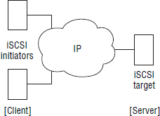
In an iSCSI SAN, initiators issue read data/write data requests to targets over an IP network. Targets respond to initiators over the same IP network. All iSCSI communications follow this request-response mechanism, and all requests and responses are passed over the IP network as iSCSI protocol data units (PDUs).
Although we will get into a lot more detail later in the chapter, it is important to note that the iSCSI PDU is the fundamental unit of communication in an iSCSI SAN. All iSCSI communication is via PDUs:
- Device discovery
- Device login
- Authentication
- SCSI commands
- SCSI data
- State-change notifications
iSCSI Is Cheap
People will often tell you that iSCSI is cheap. This can be both true and untrue, so you need to be careful.
When referring to iSCSI as cheap, people are usually comparing it to an FC SAN. While it is true that iSCSI can be deployed at a fraction of the cost of an FC SAN, the important word here is can. The reality is that an iSCSI SAN can be as cheap or expensive as you want it to be. But the adage that “you get what you pay for” holds very true for iSCSI SANs. High performance, high availability, and good security come at a cost. You could go for the mega-cheap option and throw your software initiators and software targets straight onto an existing shared IP network, cross your fingers, and hope for the best. Or you could deploy dedicated iSCSI HBAs in your servers and connect them to high-performance iSCSI storage arrays over a dedicated IP network with dedicated switches and IPsec for security. One of these options will give you high performance, high availability, and solid security. The other will not. The point is that an iSCSI SAN can be very cheap or very expensive, and what you choose must be driven by your requirements.
Now that you understand the basics, let's get under the hood.
Initiators and Targets
iSCSI SANs are composed of initiators and targets connected by an IP network. While initiators and targets are technically processes that run on the respective devices, most people refer to the server as the initiator and the iSCSI storage device as the target. In fact, rather than use these technical terms, people will be sloppy and use the terms iSCSI host and iSCSI array instead.
An iSCSI target is usually either a server with lots of disks attached or a dedicated storage array. In larger environments, the target tends to be a dedicated storage array, as these tend to provide the best performance, availability, and feature set. They also usually cost a lot more money than a standard server with a lot of shared disk.
iSCSI Interfaces
iSCSI initiators and targets require a physical interface to the network. These interfaces are usually PCI devices that are either integrated to the server motherboard or included as PCI expansion cards. They connect to the intermediate TCP/IP network via copper or fiber-optic cables.
When choosing an iSCSI interface, four major options are available. And as with most things in life, you tend to get more if you pay more. The question is this: Is what you get worth the extra you paid? The options, listed in order from cheapest to most expensive, are as follows:
Option 1: Standard Ethernet NIC with a Software Initiator This is the cheapest but probably most popular option. It takes a vanilla Ethernet NIC and converts it to an iSCSI initiator using host-based software called a software initiator. Most modern operating systems, including Linux and Windows, come with a built-in iSCSI software initiator, usually implemented as a kernel-based device driver. This makes configuring a server as an iSCSI initiator or target really cheap and really simple. However, they don't support the OS boot partition being on an iSCSI SAN, and they consume host CPU cycles, though the latter is becoming less and less of a concern with modern CPUs.
Option 2: Ethernet NIC with a TCP Offload Engine and a Software Initiator This is similar to option 1, with the major difference being that the Ethernet NIC has a TCP offload engine (TOE). This offloads processing of the TCP stack from the host CPU to the NIC, and on a busy NIC this can make a difference. However, iSCSI processing, such as building PDUs and encapsulation/decapsulation, is still handled by the host CPU. This is rarely seen in the real world.
Neither option 1 nor option 2 allows for diskless servers to boot from an iSCSI SAN without additional diskless boot software such as CCBoot.
Option 3: iSCSI Host Bus Adapter This takes things to the next level. This option offloads all the TCP and iSCSI processing from the host CPU to the processor on the host bus adapter (HBA). This increases the cost but removes the reliance on the host CPU to perform iSCSI functions. Also, from a feature perspective, iSCSI HBAs usually come with an option-ROM that allows diskless servers to be booted from the iSCSI SAN.
Option 4: Converged Network Adapter Using a converged network adapter (CNA) is similar to option 3. It offers everything that the iSCSI HBA offers (increased cost, reduced impact on host CPU, and boot from SAN) but has the added versatility of being dynamically configurable for protocols other than iSCSI, such as FCoE.
Option 1 is the most common in the real world and is extremely simple to set up in home and other small lab environments. All of these options appear to the OS as SCSI adapters. Therefore, the OS (aside from the software initiator, if any) is unable to distinguish volumes presented via the iSCSI SAN from volumes on a local disk inside the server. This makes using iSCSI SANs with existing operating systems simple and easy.
Deciding which of these is best for your environment may not be so simple. This will depend entirely upon your requirements. For example, standard vanilla NICs with software initiators and targets over a nonisolated IP network may work well in labs and small or remote offices. However, you wouldn't run your mission-critical line-of-business applications on that kind of infrastructure. For that, you want to be looking at something more along the lines of iSCSI HBAs and dedicated IP networks.
Exercise 6.1 shows how you configure the Windows Server 2012 software iSCSI initiator.
EXERCISE 6.1
Configuring the Windows Server 2012 Software iSCSI Initiator
In this example, you'll walk through the process of enabling the software iSCSI initiator included in the Windows Server 2012 operating system. At this stage in the chapter, assume a simple unauthenticated connection to an iSCSI target. You will learn how to configure authentication later in the chapter.
- From within the Windows Server Manager interface, select the Tools option from the top right-hand corner, as shown in the following image.
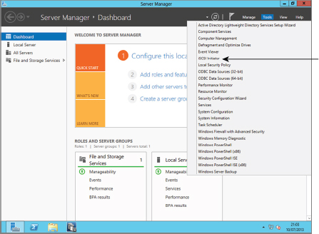
- If the iSCSI service is not already running, you will be prompted to start it. Click Yes if prompted.
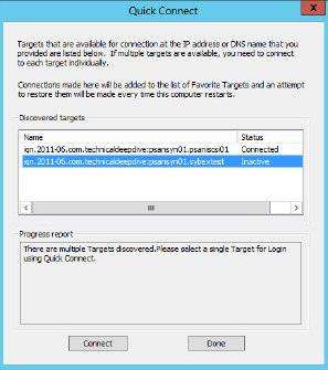
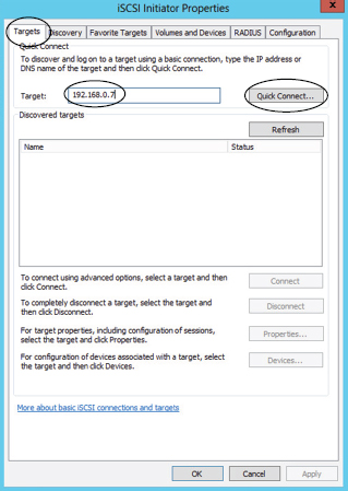
- On the resulting screen, on the Targets tab, type the IP address of the DNS name of your iSCSI target array in the Target field. Then click Quick Connect, as shown in the following image.
- The Quick Connect option returns a list of iSCSI targets running on that IP address or DNS name. From that list, select the target you wish to connect to. In the following image, the iqn.2011-06.com.technicaldeepdive.psansyn01.sybextest target is selected. Once you have selected your desired target, click Connect.
- Click OK on the following screens, as at this point you don't want to configure any advanced features.
- The iSCSI initiator now tries to connect to the selected iSCSI target. If successful, it will return you to the iSCSI Initiator Properties screen on the Targets tab and show the selected iSCSI target as Connected, as shown in the following image.
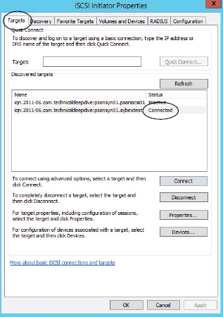
You have now configured the Windows software iSCSI initiator and connected it to an iSCSI target. You can now use iSCSI LUNs available on that target.
IP Network Considerations
The IP network is crucial to an iSCSI SAN, as it is absolutely fundamental to performance, security, and availability. If you get this part of your iSCSI environment wrong, you are in for a world of hurt!
TCP/IP is a great protocol that provides in-order delivery and error recovery, works over just about every medium known to man, and is extremely widely deployed and well-known. This can make it a great choice as a transport for SCSI. But it is vital that you understand the significance of its role in an iSCSI SAN.
Network Options
Plenty of networking options are available. The options presented next are in order from cheapest to most expensive. Again, as with iSCSI interfaces, you get what you pay for. The following list is not exhaustive, and other network options are available, but these are the most obvious and most common:
Option 1: Shared Vanilla IP Network This is the cheapest, simplest, least secure and least performant option. In this configuration, iSCSI traffic shares the same L2 broadcast domain with all other network traffic. It works and it's simple, but it is usually suited for only lab and home-office environments. If the IP network is unstable or very busy, expect performance problems and complaining users and colleagues. As an example, users backing up their iTunes library over the network in the middle of the business day can cause major packet loss and bring iSCSI performance to its knees.
Option 2: Dedicated VLAN This option, with a dedicated network connection for the iSCSI traffic on each server, offers segregation of iSCSI traffic from other network traffic. This can increase performance, and if the VLAN is nonroutable, it offers modest levels of security. As this option usually doesn't require any additional networking kit, it can keep costs down while providing decent uplifts in performance and security.
Option 3: Dedicated Physical Network This is the safe pair of hands. It offers the best in security, performance, and availability and is the most common choice in the real world. But as you may have guessed, it comes in at the highest cost. As with the iSCSI HBA or CNA, if you are deploying a mission-critical line-of-business app on an iSCSI SAN and want to be able to sleep at night, this is the option for you. An added layer of safety would be to have two dedicated switches with separate paths, effectively creating a network A and a network B, as we do in the FC world. This option would be so safe that you could sleep well at night and then also during the day!
These three aren't all of the options, but they constitute the basis of the most widely used available networking options.
Here is some key advice about general network configuration: First, go for option 2 or option 3—preferably option 3. It will save you a whole load of trouble. Next, keep the network configuration as simple as possible; don't try to be clever. Routing for inter-site connections is fine, but don't route your iSCSI network to your user network. For many vendors, it is also a best practice to disable Spanning Tree Protocol (STP) on ports connecting to iSCSI initiators and targets. Each vendor will have their own best practices around STP, but it is common for it to be disabled on ports connecting to iSCSI initiators and targets. If your network requires some form of STP, Rapid Spanning Tree Protocol (RSTP) may be preferable with PortFast enabled on all ports connecting to iSCSI initiators and targets so that these ports will immediately be in STP-forwarding mode when network events occur. BPDU Guard can also be used with ports that have PortFast enabled so that devices connected to them are prevented from participating in STP.
You may have heard that jumbo frames—Ethernet frames larger than the default maximum of 1,514 bytes, up to as much as 9,000 bytes—are a must for iSCSI. The implementation of jumbo frames can (and often does) cause problems, especially if all switches and devices in your network aren't configured with the same jumbo frame configuration. If you're confident at networking or have a good networking team, you may want to do this, as it can bring performance benefits. However, if you're not certain what you're doing in this area, you may find it's not worth the trouble.
iSCSI over a WAN or LAN
While it is possible for the IP network to be a corporate WAN or even the Internet, the vast majority of deployments are to a corporate LAN. This is so much the case that iSCSI may have been more appropriately named Intranet SCSI rather than Internet SCSI. This favoritism of the LAN comes from both a performance as well as a security perspective. Remember, storage traffic and storage traffic requirements are vastly different from most traditional uses of TCP/IP networks.
![]() Real World Scenario
Real World Scenario
Overlooking Network Requirements
One of the most common mistakes in the real world, notably among those with little iSCSI experience, is overlooking network requirements.
A company deployed iSCSI straight onto the existing shared corporate network, based on the assumption that all that is needed is any old IP network. This resulted in unpredictable and often poor performance. Weeks were wasted investigating the root cause of the performance problem, and once it was identified as an under-specced network, it involved additional cost for a dedicated network kit after the project budget was closed.
iSCSI PDU
Since we've been talking networking, let's take a quick look at the iSCSI PDU and how data is encapsulated at the various layers involved in iSCSI.
Looking a little further under the hood, the iSCSI PDU is made up of some mandatory and some optional segments. The most important of these segments is the basic header segment (BHS), which is present in every iSCSI PDU. It is a fixed 48-byte field that contains the SCSI command descriptor block (CDB) and associated target LUN info. It is always present and is always the first segment. Quite often it is the only segment in a PDU, as all other segments are optional, including PDU CRC/digests, and are usually omitted. Generally speaking, you will never have to know more than this about the makeup of an iSCSI PDU. Integrity is ensured via TCP checksums and Ethernet CRCs.
Encapsulation
iSCSI operates at the Session layer of the Open Systems Interconnect (OSI) reference model.
The life of an iSCSI I/O operation is pretty much as follows: An application issues an I/O operation to the OS/filesystem, which sends it to SCSI. SCSI creates the CDB and passes this to the iSCSI layer, which incidentally SCSI sees as just any old transport. CDBs and associated target LUN data are encapsulated by iSCSI into PDUs at the Session layer and passed further down the layers until they hit the wire for transport across the network. As they are passed down the different layers, additional layers of encapsulation are added. Figure 6.2 shows how iSCSI PDUs are encapsulated within TCP segments and then IP packets and then finally Ethernet frames.
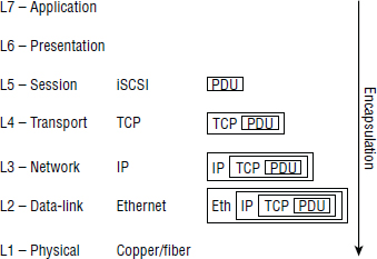
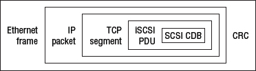
There is nothing iSCSI-specific about the encapsulation once below the Session layer; TCP headers are used for reliable delivery, and IP headers for packet routing. Figure 6.3 shows an encapsulated iSCSI PDU.
There is no implicit 1:1 mapping of iSCSI PDUs to TCP segments. An iSCSI PDU can span more than one TCP segment, IP packet, and Ethernet frame. Also, because of the nature of IP networks, frames, and therefore PDUs, may arrive at the target out of order. This is not a problem, as the TCP stack on the receiving end takes care of reordering segments and ensuring in-order delivery to the iSCSI layer.
Within an iSCSI session, command sequencing is tracked via command sequence numbers (CmdSN). The CmdSN is incremented one digit for each command in a sequence.
Once received by the target, each of these encapsulation layers is stripped off, including the iSCSI PDU encapsulation, until all that is left is the SCSI CDB. This encapsulation/decapsulation will occur fastest on systems that have iSCSI HBAs or CNAs, as the encapsulation/decapsulation is performed by the HBA or CNA and not by the host CPU.
If iSCSI PDU size exceeds maximum segment size of the TCP layer, the PDU will be fragmented across multiple TCP segments. This can be fixed by manipulating the Maximum Transmission Unit MTU size on your network, but be careful. Do this only if you know what you are doing, as it breaks the cardinal rule of “keep things simple.”
Of course, the underlying transport for the IP network could be any link-layer protocol and does not have to be Ethernet. However, it almost always is, so throughout this chapter, we assume it is Ethernet.
iSCSI Names
Every device on an iSCSI SAN needs a name. No name, no identity on the iSCSI SAN. iSCSI names are tied to iSCSI nodes and not a specific interface card in a node. This is important, as it allows the name to remain with the node even if NICs and HBAs are swapped around between devices.
iSCSI names are also permanent and globally unique. They do not change if the IP address or fully qualified domain name (FQDN) of a node or card changes.
iSCSI Qualified Names
Despite there being three iSCSI naming conventions available, the iSCSI Qualified Name (IQN) is by far and away the most popular and widely deployed. With this in mind, this section concentrates on the IQN and then touches on the other two types.
IQNs can be up to 233 bytes in length, are not case sensitive, cannot contain spaces, and are globally unique. They are also location independent, meaning that if an iSCSI node's IP address or hostname changes, the IQN is not affected. In fact, an iSCSI device can keep its IQN for its entire life. An IQN, however, is not burned in like an Ethernet MAC address or FC World Wide Name. It can be easily changed by an administrator if required.
iSCSI names are hierarchical, and within an IQN, three characters have special meaning:
- The dot .
- The colon :
- The dash -
These characters partition the iSCSI name. You will see how they are used later in this section.
Uniqueness of IQNs is achieved via two means. First, the IQN includes a domain name that must be owned by the company owning the iSCSI SAN. Second, to avoid situations where a company may have bought the rights to a domain name previously used by another company, a date is included in the IQN. This should be a date from the time the company deployed the iSCSI SAN-owned the rights to the domain name. While it is possible to ignore these guidelines, it is highly recommended that you follow this practice if changing iSCSI names!
More often than not, companies don't bother changing the default IQN that their devices come configured with. And this is one good way of ensuring uniqueness, as the vendor will have already followed the guidelines outlined in this section. For example, an EMC VNX array at a customer site has the following default IQN on one of its iSCSI ports: iqn.1992-04.com.emc:cx:ckm00124XXXXXXX.a10.
Interestingly, domain names used in iSCSI names do not have to be resolvable on the Internet or on the local corporate LAN. DNS resolution plays no part in defining and using iSCSI names. The reason that the domain name must be owned by the company to whom the iSCSI SAN belongs is purely to maintain global uniqueness of iSCSI names.
Now that you have some of the basics, let's take a look at an example IQN:
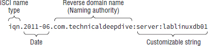
iqn.2011-06.com.technicaldeepdive:server:lablinuxdb01
While this might look a little complicated at first, it absolutely isn't.
IQNs names are broken into four fields:
- Type
- Date
- Naming authority
- Customizable string
Looking at our example, the type is iqn, identifying this name as an IQN type name (we will discuss the other two types shortly).
The date is generally the year and month at which the company registered the domain name that will be used in the name. The date format must be YYYY-MM. It is this combination of registered domain name and date at which the domain name was registered that ensures global uniqueness.
The naming authority is the domain name in reverse format. Reverse format means that the extension comes first, in this case com, followed by the . divider, followed by technicaldeepdive.
The customizable string can be any UTF-8 text that you as an administrator decide. However, as when choosing server names, it is highly recommended that you give some thought to defining a meaningful and scalable naming convention.
The format is as follows:
type.YYYY-MM.reversedomainname:customizablestring
Type is always followed by a period (.), the year is always separated from the month by a dash (-), the date and the reverse domains name are always separated by a period (.), and the reverse domain name and the customizable string are always separated by a colon (:). What comes after the colon in the customizable string is pretty open. You are then free to use the special characters if you wish, but from this point on in the name, they no longer have any special meaning.
Now that you know the major components and delineators that make up an IQN, let's take another look at our previous example as presented in Figure 6.4.
Alternative iSCSI Naming Conventions
Alternatives to the IQN naming standard include Extended Unique Identifier (EUI) and T11 Network Address Authority (NAA). Both provide global uniqueness but are far less popular than IQN, and neither are human readable, at least not by normal human beings.
The EUI name format (EUI-64) consists of the letters eui, followed by a period (.), followed by 16 hex digits. For example:
eui.0123456789ABCDEF
The value of the 16 ASCII hex digits is formed by combining the Organizationally Unique Identifier (OUI) assigned to the company by the Institute of Electrical and Electronics Engineers (IEEE), and an extension identifier assigned by the company. The two combined result in a 64-bit (16 hex character) unique ID. The most significant bits represent the OUI, and the least significant bits the extension ID. It is unlikely that you will have the misfortune of having to deal with EUI names.
The NAA naming format was added to iSCSI in 2005 because both FC and SAS supported NAA naming formats and iSCSI did not. The thinking behind adding NAA was interoperability with FC and SAS. It is mercifully rare in deployment. However, just in case you come across this in an exam, the NAA naming format is as follows: naa, followed by a period (.), followed by what is referred to as the NAA value. The NAA value can be either 64-bit or 128-bit. 64-bit NAA values are 16 hex characters, whereas 128-bit NAA values are 32 hex characters. NAA values are not human readable.
iSCSI Aliases
Aliases can also be assigned to an initiator or target, allowing you to assign an even more user-friendly name to devices. However, these cannot be used in place of proper iSCSI names for operations such as discovery, login, and authentication. They are useful only for assigning more human-readable names to iSCSI devices in management tools and for similar purposes.
Wrapping up naming, IQN format is by far the most widely deployed and by far the most human friendly. EUI and NAA formats are horrific, but mercifully rare in their deployment.
Device Discovery
For an initiator and target to communicate, the initiator needs to be able to discover the target. To do this, the initiator needs to know three things about the target: IP address, TCP port, and iSCSI name. This information is obtained via the discovery process.
There are a few methods of discovery, intended to suit different-sized iSCSI SANs. Here are the various options, starting with those suited to the smallest environments and finishing with those suited most to large environments:
Manual Device Discovery In the very smallest environments, you can manually configure initiators with a file that lists available targets (IP address, TCP port, and iSCSI name). But this is neither dynamic nor scalable, and for these reasons it is rarely used. Technically speaking, no discovery is actually performed, as the list of targets is preconfigured on the initiators.
SendTargets This assumes prior knowledge of the IP address and TCP port used by the network portal of the target. The initiator issues the SendTargets command to the network portal on the target, and the target responds (request-response) with a list of available targets. This is common in small to medium iSCSI SANs and configurations that employ iSCSI gateways, which are rare and are discussed at the end of the chapter.
Automatic Device Discovery The final and most scalable options are those where the initiators have no prior knowledge of any targets on the SAN and must seek out targets on their own. Service Location Protocol (SLP) is the first and requires an SLP agent to be running on the initiator and the target. The SLP user agent on the initiator issues multicast messages to locate targets, and the service agent on the target responds. SLP is ideal for small to medium iSCSI SANs but not for large SANs. To be honest, it's not deployed that often. For large SANs, iSNS is recommended. iSNS is discussed in more detail in the “iSNS” section later in this chapter.
Once an initiator has discovered a target, the next step is to perform an iSCSI login with that target.
iSCSI Sessions
Once iSCSI devices (initiators and targets) are connected to the IP network and initiators have discovered targets, they can start the process of establishing sessions. A session is a communication path between a single iSCSI initiator and a single iSCSI target. Sessions contain at least one, and potentially more, TCP connections. It is over these TCP connections that commands and data are sent, in the form of iSCSI PDUs. This might sound like a lot to take in, but it's simple and by the end of this chapter it will be crystal clear. Let's take a look in more detail.
To be technically accurate, when discussing iSCSI communications, iSCSI transfer direction should be described from the viewpoint of the initiator, meaning that outbound iSCSI traffic is heading away from the initiator, and inbound traffic is heading toward the initiator. Granted, this is a minor point, but worth knowing.
Device Login
Before iSCSI sessions can be created, and therefore before data can be read and written, an initiator and a target need to perform the iSCSI login process. iSCSI login is a two-phase process:
- Security negotiation
- Parameter negotiation
Of these two phases, security negotiation is optional. However, if security negotiation is to happen, it must happen before the negotiation of other session parameters.
The login process is started by initiators issuing iSCSI login request PDUs to the IP address and TCP port of the iSCSI target. This port can be the default well-known IANA-assigned port 3260/tcp, or a user-configured port. In iSCSI parlance, this combination of an IP address and listening TCP port on an iSCSI target is known as a network portal.
On receipt of iSCSI login requests, the target responds with iSCSI login responses. As we should expect by now, login requests and login responses are formed as iSCSI PDUs, and follow the familiar request-response model common throughout iSCSI.
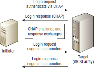
Figure 6.5 shows the entire login, authentication, and parameter negotiation process.
Authentication
While it is not mandatory, it is highly recommended that initiators and targets authenticate each other. After all, IP networks are notoriously prone to attacks such as spoofing and man-in-the-middle attacks—although deploying dedicated isolated networks goes some way to avoiding man-in-the-middle attacks. To get around this, Challenge-Handshake Authentication Protocol (CHAP) should be used for authentication.
Although CHAP can help with authenticating initiators and targets, it does nothing to protect data in flight; data is still sent in cleartext. Therefore, if you have serious concerns about security, you should consider other network-level precautions, such as isolated networks and encryption technologies such as IPsec. However, while IPsec is great at providing cryptographic services for in-flight data, it can have a significant performance overhead.
While there is a feeling in the industry that CHAP is a relatively weak authentication method, using a random or otherwise strong password (shared secret) can significantly help. If you choose a simple password that is prone to dictionary attacks, the benefit of using CHAP is significantly reduced. Also, the iSCSI standards require that traffic flowing from the initiator to the target have a different shared secret than traffic flowing from the target to the initiator. This also helps avoid some of the more well-known weaknesses with CHAP.
Although other non-CHAP-based authentication options may sometimes be available, these should be considered with care. Because CHAP is the only security authentication mechanism specified in the standards, it is by far the most widely implemented and supported. The niche nature of other potentially stronger options makes them more difficult to implement and then support, as well as being subject to potential interoperability issues.
The best advice, if you are security conscious, is to deploy to an isolated nonroutable network, use CHAP for authentication with strong shared secrets, and use IPsec to encrypt the data in transit. It is also common practice to keep the management interfaces on a separate management network/VLAN. The point is that there are many options, and you can pick and choose which are appropriate for your requirements.
Let's now run through configuring a CHAP authentication on an iSCSI target (array) and an iSCSI initiator in Exercise 6.2 and Exercise 6.3.
EXERCISE 6.2
Configuring CHAP Authentication on an iSCSI Target (Array)
In this exercise, you will configure a target on an HP StoreVirtual iSCSI array to require CHAP and mutual CHAP authentication.
- In the GUI for our StoreVirtual iSCSI array, select the iSCSI target from the tree pane. Right-click the target (server) and choose Edit Server from the context menu, as shown here.
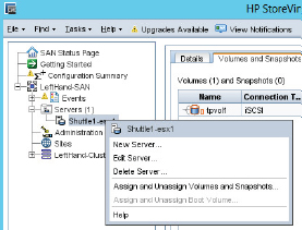
- In the Edit Server configuration screen, select the CHAP Required radio button in the Authentication area toward the bottom of the screen. Enter a username and a password for the Target Secret and Initiator Secret. Make sure you remember these passwords.
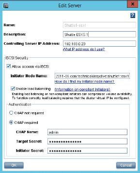
You have now configured CHAP authentication for the Shuttle1-esx1 iSCSI target on the HP StoreVirtual iSCSI array. This target will no longer accept unauthenticated requests to connect/log in.
You can download evaluation copies of the HP StoreVirtual VSA as a VMware ODF file to play around with in your home lab.
EXERCISE 6.3
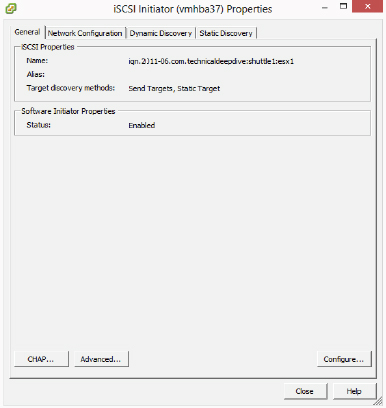
Configuring CHAP Authentication on VMware ESXi iSCSI Initiator
In this exercise, you will walk through the steps of configuring CHAP authentication on VMware ESXi running the software iSCSI initiator.
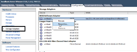
- Log in to vCenter, or directly to the ESXi host, and navigate to the Storage Adapters section of the Configuration tab to access the properties.
- On the resulting Properties screen, click the CHAP button in the bottom-left corner.
- The CHAP Credentials screen appears. In the CHAP (Target Authenticates Host) area, choose the Use CHAP option from the Select Option drop-down menu. In the Mutual CHAP (Host Authenticates Target) area, make the same selection. Enter the Name and Secret credentials. Then click OK.
- A rescan of the HBA will be required. Click Yes on this screen.
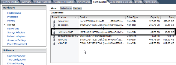
- Once the rescan has completed, go to the Storage area of the Configuration tab in your vCenter GUI, and you will see your iSCSI LUNs.

In the image, you have a new 50 GB iSCSI LUN visible from the HP StoreVirtual iSCSI array. If you look closely, you will see that the device is showing as a LEFTHAND iSCSI-Disk. This is because HP has rebranded their LeftHand product as StoreVirtual, but under the covers the device still identifies itself as LeftHand.
Once the iSCSI login process is complete, and assuming it is successful, the session enters what is known technically as full-feature phase (FFP).
Full-Feature Phase
Full-feature phase is where the action happens. Once a session is in this phase, commands and data can be sent between initiators and targets. Prior to this, only login-related PDUs are permitted between the initiator and target.
It is time for a quick recap of the iSCSI login process. iSCSI login is the process that negotiates security, builds the TCP connections, and defines all the parameters that will be used when the session enters FFP. The login process is composed of a set of request-response PDUs between an initiator and a target. First up, the TCP connections are established, and then the iSCSI login session. After successful login, the session enters FFP, and from then on initiators and targets are free to go about their everyday business of reading and writing data.
FFP is composed of one or more iSCSI sessions. These sessions represent communication between an initiator and a target. Each session is composed of one or more TCP connections, and only a single initiator and a single target can participate in a single session. If an initiator wants to communicate with more than one target—let's say, for instance, two targets—it must have at least two sessions (one session per target).
Let's take a look at a quick example of an initiator communicating with two targets. Host A is a database server with two LUNs from Target A, which is a high-performance iSCSI storage array. LUN1 is used for the database, and LUN2 is used for logs. Host A also has a single LUN presented from Target B, which is a deduplicating storage array. This LUN (LUN 3) is used for a backup area. It is perfectly normal for Host A to have connections to these two targets, but in order to do so, there will need to be a minimum of two sessions—one for the communications between Host A and Target A, and the other between Host A and Target B. See Figure 6.6. Each of these sessions may have one or more TCP connections.
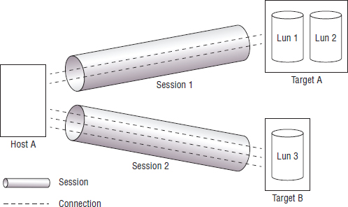
Sessions are identified by a unique session ID (SSID) comprising an initiator component known as the initiator session ID (ISID) and a target component known as the target portal group tag (TPGT). Each TCP connection is uniquely identified within the context of a single iSCSI session by a connection ID (CID). This CID is used during login and logout and various other operations.
Within a session, related requests and responses must have what is known as connection allegiance. Connection allegiance requires that all related requests and responses occur over the same TCP connection. For example, if an initiator makes a READ request over TCP Connection X, the response from the target to the initiator must be over TCP Connection X. The same goes for WRITE requests issued from an initiator. And just in case it hasn't sunk in yet, all communication within an iSCSI session is done via iSCSI PDUs. It is the iSCSI layer (Session layer of the OSI model) that builds PDUs and manages all sessions.
Initiators are responsible for performing logouts. In the real world of an iSCSI administrator, it is not necessary to know intimate details of this process.
In the real world, many popular iSCSI arrays, such as Dell EqualLogic, present a separate target for each LUN, simplifying LUN masking.
iSNS
iSNS stands for Internet Storage Name Service, and if you are administering a large data center with many iSCSI arrays, you may want to deploy iSNS. And if you do so, you will want to know it well. It is a godsend to large iSCSI environments.
At a high level, iSNS is a simple centralized database containing configuration data about your iSCSI SAN. Initiators and targets can register information with the iSNS as well as query information from it. Querying the iSNS allows devices on the iSCSI SAN to determine the topology of the iSCSI SAN as well as capabilities and properties of other devices that are visible to it. Initiators and targets can also register attributes with the iSNS, making it a dynamic repository that can greatly simplify iSCSI SAN management. Initiators register with the iSNS and query it for a list of available targets. Targets register with the iSNS so that they can be discovered by initiators. Both can also register for state updates from the iSNS.
If you know FC SAN and are familiar with the FC Simple Name Service (SNS), you are 99 percent of the way to understanding iSNS, as iSNS is modeled on FC SNS.
iSNS provides the following services in an iSCSI SAN:
- Name service
- Partitioning of the iSCSI SAN into discovery domains
- Login services
- State-change notifications
- Mapping FC to iSCSI devices
Two of these merit further discussion—partitioning and state-change notifications. Before we do this, let's take a quick moment to cover some of the basic components of the iSNS service.
The protocol used by iSCSI devices to communicate with the iSNS is iSNSP (iSNS Protocol). It is a lightweight request-response protocol, and the default TCP port that the iSNS listens on is 3205. All communication between initiators, targets, switches, and the iSNS occurs via iSNSP. This is, of course, subsequently encapsulated within the obligatory TCP segments, IP packets, and Ethernet frames for delivery across the IP network.
The iSNS client running on each initiator or target is the process responsible for locating the iSNS service as well as all communication with the iSNS.
The iSNS server hosts the iSNS database and is responsible for making that database available to the iSCSI SAN, so that devices can register with and query information from it.
The iSNS database is the information store for the configuration of the iSCSI SAN. This is a simple lightweight database and does not require complex and expensive stand-alone database servers. It can be Lightweight Directory Access Protocol (LDAP) integrated. It can be dynamically updated by initiators and targets.
Now that you know the major components that make up and interact with the iSNS, let's take a closer look at the services iSNS provides.
Discovery Domains
Discovery domains are a way of partitioning your iSCSI SAN into smaller, more manageable, and more secure zones. Each of these zones is referred to as a discovery domain, or DD for short.
In a nutshell, initiators and targets are administratively assigned to discovery domains. Once assigned to a discovery domain, devices can only discover, log in, and communicate with other devices that share a common discovery domain. It is possible, and common, for devices to be members of multiple DDs, but the main point to note is that in order for an initiator and a target to communicate with each other, they must be members of a common DD.
Partitioning your iSCSI SAN into smaller discovery domains has several advantages. The first advantage is security. When DDs are implemented, devices can see and communicate only with other devices in the same DD. Not only can they not log in to other devices outside their discovery domains, they will not even know of the existence of devices outside their discovery domains. This leads to a second important advantage of discovery domains. By restricting the view of the SAN, they restrict the number of devices that can be discovered and logged in to. As an example, let's assume a wide-open iSCSI SAN (an administrator's nightmare!) with no discovery domains implemented. In this wide-open example, if no discovery domains were implemented, you may get situations where every initiator on the iSCSI SAN attempts to log in to and query every other device on the iSCSI SAN. This would be time-consuming and wasteful of resources, not to mention a security risk.
The implementation of discovery domains relies on the initiator playing by the rules, and the target rejecting logins that come from devices not in the appropriate discovery domain. Discovery domains on their own do not have a mechanism to strictly enforce them. For example, there is no mechanism to drop network packets from an initiator to a target that it does not share a discovery domain with. In effect, there is nothing inherent in a discovery domain to physically stop a misbehaving initiator from breaking the rules. In this sense, discovery domains are a form of security by obscurity. Initiators can't mess around with targets they don't know about.
As a security precaution, it is strongly recommended that you operate a closed-door policy when it comes to discovery domains. This is the opposite of a wide-open policy. In a closed-door policy iSCSI SAN, new devices on the iSCSI SAN are automatically registered with no discovery domain, leaving them effectively off the iSCSI SAN until you explicitly configure them into a discovery domain. This is a best practice in both iSCSI and FC SANs.
From a security perspective, iSNS and discovery domains restrict only device discovery. Masking of devices on a target, CHAP for authentication, and IPsec for privacy of in-flight data are all still necessary for the ultimate in security. Discovery domains absolutely do not do away with the need for these other technologies.
Figure 6.7 shows a small iSCSI SAN with two initiators, Init1 and Init2, and a single target with two network portals. The iSCSI SAN is divided into two discovery domains. In this example, Init1 is unaware of the existence of Init2.
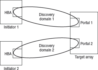
As an administrator, you can place one or more network portals of a given network entity into a discovery domain. Think of network portals as one or more interfaces on an iSCSI target. By placing network portals into discovery domains, you are controlling which interfaces (network portals) will send and receive traffic to and from particular initiators. Looking back at Figure 6.7, we can see that network portal 1 (P1) will permit traffic to and from Init1 but not Init2. Likewise, network portal 2 (P2) will permit traffic to and from only Init2 and not Init1.
A portal group is a collection of network portals within a single network entity/iSCSI target. This is not too dissimilar to a NIC team. It is possible for sessions to have multiple connections that span multiple portals within a portal group. A target portal group tag is just a numerical string used to identify a target portal group.
A quirk worth noting is that if you place an entire network entity into a DD rather than explicitly placing a particular network portal into the DD, all portals for that network entity will permit traffic for that discovery domain.
For a discovery domain to be active and effective (in use), it must be a member of the active discovery domain set (DDS). A DDS contains many discovery domains, and the discovery domains that are members of the active DDS are the only active and operational discovery domains.
State-Change Notifications
State-change notifications (SCNs) are a method of relaying relevant configuration and topology information to devices on the iSCSI SAN.
The SCN service runs on the iSNS server, meaning that you need to be running an iSCSI SAN with iSNS to benefit from SCNs. For day-to-day configuration and administration of your iSCSI SAN, that is probably about as much as you will need to know. However, there is more to it that may be of benefit when troubleshooting or in exams.
The iSNS issues SCNs in response to events and changes on the iSCSI SAN. It is the iSNS client running on the initiator or target that is responsible for registering with the iSNS for SCN updates. If an initiator or target does not register itself for SCNs, it will not receive them.
Only two types of SCN exist:
- Regular SCNs are issued to all registered devices within a discovery domain. So, in order for a device to receive a regular SCN, it must have registered to receive them, and reside in a discovery domain to which the SCN is issued. This twofold approach keeps SCN traffic to a minimum and ensures that the messages that do reach a device are relevant.
- Management SCNs can be registered for by only known control stations, meaning that regular initiators and targets cannot register for management SCNs. Also, the distribution of management SCNs is not restricted to the boundaries of discovery domains. As an administrator, you can control the list of authorized control stations (also known as management stations).
Registration for SCNs is done at iSCSI login time.
Administering the iSNS
A management station, sometimes referred to as a control station, is a special entity on an iSCSI SAN with carte-blanche access to the iSNS. This administrative access to the iSNS is usually out-of-band (OOB), meaning that it is accessed over an interface (IP address) that is separated from the real iSCSI traffic and usually dedicated just to management traffic. Some of the common administrative functions performed by a management station include the following:
- Creating, enforcing, and destroying discovery domains
- Maintaining the list of authorized control stations
- Maintaining the Management SCN setting
- Setting whether the default discovery domain and DDS are enabled or disabled (recommend disabled!)
There is a dedicated iSNS Management Information Base (MIB), iSNSMIB, for managing and monitoring iSNS via Simple Network Management Protocol (SNMP).
As the iSNS can become so crucial to the daily operation of your iSCSI environment, it needs appropriate hardware resources. Overloading the iSNS can result in SCNs not being generated and other problems.
Security
As security is such a hot and vital topic, it's worth taking a few minutes to quickly recap some of the security-related principles and best practices that we've already discussed as well as mention one or two more.
The iSCSI standard outlines the use of CHAP as a mechanism for initiators and targets to authenticate each other. However, CHAP does not have the greatest reputation in the network security world. The reality is that if weak CHAP shared secrets (passwords) are used, then CHAP will deter only the very crudest of attacks. However, if strong secrets (not using common words that can be found in a dictionary, including numbers, and so on) are used, it can be a useful security precaution. Therefore, it is highly recommended to use CHAP and to use it with strong secrets. However, even with strong secrets, it is important to note that CHAP provides only initiator and target authentication—that is, ensuring that the initiator and target are who they say they are. It does absolutely nothing to secure data transmitted over the wire.
So even with a well-configured CHAP solution, iSCSI still transmits data over the network as cleartext with absolutely no native cryptographic services. So if you don't use something like IPsec, all your data will be transferred in plain text and easily readable by anyone listening in. If this is a concern, you should seriously consider IPsec. If it's not a concern, you probably don't need IPsec.
As an additional security measure, it might be good practice to operate a dedicated physically isolated network, or nonroutable VLAN, for iSCSI traffic. You should also keep management interfaces off the iSCSI network.
If using iSNS, it is recommended to implement discovery domains and disable the default discovery domain. Doing so will mean that only devices that are administratively added to discovery domains will be able to discover and communicate with other devices on the SAN.
Most iSCSI targets also support LUN masking, where resources (LUNs) on a target are masked and visible to only specific initiators. LUN masking should always be used.
Other security measures exist, including stronger authentication methods, but many are niche and can be hard to support when the going gets tough. Implementing the preceding recommendations will be enough to satisfy most security requirements and ensure you can sleep well at night knowing you don't have any gaping security holes in your iSCSI SAN.
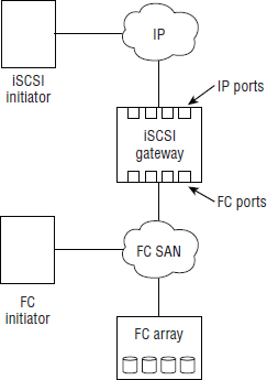
iSCSI Gateways
iSCSI gateways are used when an existing Fibre Channel storage array, with only FC ports, exists in an environment and you want to connect iSCSI initiators to it. The iSCSI gateway acts the way a network gateway should, by performing protocol translation between iSCSI and Fibre Channel Protocol (FCP). On one side of the gateway are the Ethernet port for the iSCSI connectivity, and on the other side are FC ports for the FCP traffic. It is the gateway that is configured as the iSCSI target, and not the FC storage array.
This is sometimes called a bridged topology or a gateway topology and is not as common as native iSCSI environments. This kind of configuration adds components and complexity to an iSCSI and FC SAN and should not be favored over a native iSCSI SAN.
What is more common than an iSCSI gateway configuration is a storage array that has both iSCSI and FC connectivity (sometimes referred to as a multiprotocol array). These tend to be high-end, very reliable systems and do not suffer from the added complexity issues that gateway configurations do. A simple iSCSI gateway configuration is depicted in Figure 6.8.
Chapter Essentials
Understanding iSCSI Protocol Conceptually speaking, iSCSI is a SAN protocol that maps SCSI over IP and operates a simple request-response model where all messages between initiators and targets occur via iSCSI protocol data units, often referred to as simply PDUs or messages.
iSCSI Performance iSCSI performance is influenced by three main components. Best and most consistent initiator performance is achieved with dedicated iSCSI HBAs. Best and most consistent target performance is achieved by purpose-built iSCSI arrays. Best and most consistent network performance is achieved by dedicated network switches.
Encapsulation and IP SCSI commands are encapsulated at each layer of the network stack for eventual transmission over an IP network. The TCP layer takes care of transmission reliability and in-order delivery, whereas the IP layer provides routing across the network.
iSCSI and Security Multiple layers of security should be implemented on an iSCSI SAN. These include: CHAP for authentication, discovery domains to restrict device discovery, network isolation, and IPsec for encryption of in-flight data.
Summary
In this chapter you learned about the basics, as well as some of the advanced features, of iSCSI Storage Area Networks. We talked about iSCSI initiators and the different initiator options available, as well as different network options. When talking about initiators and networks, we discussed how each of the options influenced performance, availability, and cost. We also talked about some of the theory that is fundamental to iSCSI SANs, including iSCSI qualified names (IQN), device discovery, login, authentication, state change notifications, and discovery domains.