
In this recipe we are going to take the quad and triangle renderers from the previous example and apply some texture using a shader resource view (SRV), a sampler state object, and changes to the shader program.
The final output from the example will look something like the following figure:
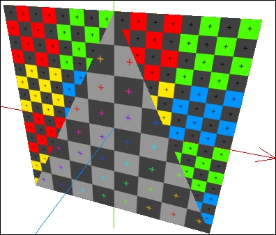
Textured triangle and quad
For this recipe, we will continue from where we left of in the Rendering primitives recipe.
There are two texture files included with the sample code that you will also need. Alternatively, you may use any BMP, JPG, PNG, or even DDS formats. For reference, the two textures used in this project are shown in the following figure:
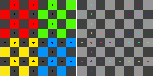
The two 256x256 textures used in this recipe
For this recipe, we will first change the HLSL shader code to accept the SRV and sampler state. Then, we will update our renderers to use texture coordinates, load the textures, and bind the SRVs to the appropriate stages of the pipeline. To do so, follow the given steps:
- Add the two texture files,
Texture.pngandTexture2.png, to the project. Then, select Copy if newer as the Copy to Output value in the Properties window. - Add the following global variables to
Simple.hlsl:// Globals for texture sampling Texture2D ShaderTexture : register(t0); SamplerState Sampler : register(s0);
- Modify
Simple.hlslso that the vertex structures look like the following code snippet:struct VertexShaderInput { float4 Position : SV_Position; float2 TextureUV : TEXCOORD0; }; struct VertexShaderOutput { float4 Position : SV_Position; float2 TextureUV : TEXCOORD0; }; - Change the
VSMainHLSL function so that it passes through aTextureUVproperty rather thanColor.output.TextureUV = input.TextureUV;
- Replace the content of the
PSMainfunction so that it samples the texture as shown in the following code:// Sample the pixel color using the sampler and texture // using the input texture coordinate return ShaderTexture.Sample(Sampler, input.TextureUV);
- Within our Direct3D application class (
D3DApp), change the vertex layout initialization to include the texture coordinate:vertexLayout = ToDispose(new InputLayout(device, ShaderSignature.GetInputSignature(vertexShaderBytecode), new[] { // input semantic SV_Position=vertex coord in object space new InputElement("SV_Position",0,Format.R32G32B32A32_Float, 0, 0), // input semantic TEXTCOORD = vertex texture coordinate new InputElement("TEXCOORD", 0, Format.R32G32_Float, 16, 0) })); - In each of the renderers, add the following private member fields:
// Shader texture resource
ShaderResourceView textureView;
// Control sampling behavior with this state
SamplerState samplerState;
- And then, initialize member fields within the
CreateDeviceDependentResourcesmethod, changingTexture.pngtoTexture2.pngin theTriangleRendererclass.// Load texture textureView = ToDispose( ShaderResourceView.FromFile(device, "Texture.png")); // Create our sampler state samplerState = ToDispose( new SamplerState(device, new SamplerStateDescription() { AddressU = TextureAddressMode.Wrap, AddressV = TextureAddressMode.Wrap, AddressW = TextureAddressMode.Wrap, Filter = Filter.MinMagMipLinear, })); - Within the
DoRendermethod of each primitive renderer, add the following code:// Set the shader resource context.PixelShader.SetShaderResource(0, textureView); // Set the sampler state context.PixelShader.SetSampler(0, samplerState);
- In
AxisLinesRenderer.cs, change the vertex buffer creation so that each of theVector4vertex positions are only an array of floats. Then, replace the color with a texture coordinate as shown here:axisLinesVertices = ToDispose(Buffer.Create(device, BindFlags.VertexBuffer, new[] { /* Vertex Position Texture UV */ // ~45x10 -1f, 0f, 0f, 1f, 0.1757f, 0.039f,// - x-axis 1f, 0f, 0f, 1f, 0.1757f, 0.039f,// + x-axis // SNIP... // ~135x35 0f, -1f, 0f, 1f, 0.5273f, 0.136f,// - y-axis // SNIP... // ~220x250 0f, 0f, -1f, 1f, 0.859f, 0.976f, // - z-axis // SNIP... })); axisLinesBinding = new VertexBufferBinding(axisLinesVertices, Utilities.SizeOf<float>() * 6, 0); - Within
TriangleRenderer.cs, change the vertex buffer creation to use the following vertices (be sure to also update theVertexBufferBindingmethod)./* Vertex Position Vertex UV */ 0.75f, -0.75f, -0.001f, 1.0f, 1.0f, 1.0f, // Base-right -0.75f, -0.75f, -0.001f, 1.0f, 0.0f, 1.0f, // Base-left 0.0f, 0.75f, -0.001f, 1.0f, 0.5f, 0.0f, // Apex
- Within
QuadRenderer.cs, change the vertex buffer creation as follows:/* Vertex Position texture UV */ -0.75f, 0.75f, 0f, 1.0f, 0.0f, 0.0f, // Top-left 0.75f, 0.75f, 0f, 1.0f, 2.0f, 0.0f, // Top-right 0.75f, -0.75f, 0f, 1.0f, 2.0f, 2.0f, // Base-right -0.75f, -0.75f, 0f, 1.0f, 0.0f, 2.0f, // Base-left
- Compile and run (F5) your project. You should see the figure shown at the beginning of this recipe.
Tip
If it looks like you are missing vertices or the primitives are drawing incorrectly, you may have specified the incorrect size when creating the vertex buffer binding. Make sure that it reads
Utilities.SizeOf<float>() * 6noting that we are usingfloat(notVector4)and there are six of them per vertex.
First, we will update our HLSL to include two global variables for storing the SRV and the sampler state we created in our renderers. Next, we will update our shader to accept a texture
UV coordinate as input rather than a color (float2 TextureUV : TEXCOORD0;).
Note
Texels, in a 2D texture, are addressed using the x and y axes. However, as these names are already used in 3D space, we refer to them as UV coordinates instead. UV coordinates are normalized, where the upper left corner is 0(U),0(V) and the bottom right corner is 1(U),1(V). Therefore, the UV coordinate for the pixel located at 100, 150 within a 200 x 200 texture would be 0.5(U), 0.75(V) (that is, 100/200, 150/200). There is also a third component, W (z axis) that can be used to address 3D textures or volume textures and cube maps. Therefore, the full term is therefore a UVW coordinate, however, we generally use a 2D texture and drop the W.
The vertex shader now passes through an unchanged UV coordinate. The pixel shader then determines the color by sampling from the ShaderTexture global variable provided by the SRV by using the sampler state and interpolated vertex UV coordinate.
Since we changed the structure of the vertex, we must also update the input layout for the IA so that it is now expecting four floats for the vertex position and two floats for the UV.
In each of the renderers, we are loading a SRV directly from the texture file using ShaderResourceView.FromFile. Internally this creates a Texture2D resource and returns a SRV so that it can be bound to the pipeline.
Note
ShaderResourceView.FromFile is unavailable for the Windows Store apps, Chapter 11, Integrating Direct3D with XAML and Windows 8.1, covers how to replace this method in the recipe Loading and compiling resources asynchronously.
The SamplerState global variable that we create controls how the sampling in the pixel shader determines the correct coordinate and which filter method to use. The AddressU/V/W properties of the description control how to handle values outside of the 0.0 - 1.0 UVW range. For example, whereas TextureAddressMode.Wrap repeats the texture, using TextureAddressMode.Clamp will make anything outside the range appear smeared (clamping to zero or one)—try clamping the quad renderer to see this effect.
The Filter property of the sampler state description controls which texels will be used and how they are combined to generate the final pixel. Here, we have used Filter.MinMagMipLinear, which provides a better quality result than the default Filter.MinMagMipPoint value. The sampler will now use linear interpolation when minifying, when magnifying, and for mid-level sampling. Zooming in and out will show the effect of the filtering method used. Try changing the triangle or quad back to the default and see the contrast in quality. Also, try doing this with other filter values.
To make the SRV and sampler state available to the pixel shader, we have bound them with a call to PixelShader.SetShaderResource and PixelShader.SetSampler within DoRender of each renderer. We have specified slot 0 for both of these functions which correlate to register(t0) and register(s0) within the shader for the texture and sampler state respectively.
Next, we have defined our new vertex buffers. These buffers are now represented by an array of six floats for each vertex. The axis lines are sampling single texels for each line that approximates the original colors used (red/green/blue). The triangle is sampling within the bounds of the texture (between zero and one) to select the entire width of the texture at the base and the top-center of the texture at the apex. The quad is addressing twice the width and height of the texture (between zero and two) that combined with the TextureAddressMode.Wrap value that is repeating the texture four times within the surface.
- See Chapter 3, Rendering Meshes, and Chapter 4, Animating Meshes with Vertex Skinning, for more examples of texture sampling and a discussion on UV unwrapping
- The recipe Loading and compiling resources asynchronously in Chapter 11, Integrating Direct3D with XAML and Windows 8.1, demonstrates how to load images into an SRV for Windows Store apps