
In this recipe, we will update our vertex structure, constant buffers, and vertex shader to support the transforming of vertices based on an underlying bone structure.
The key component of vertex skinning or skinning is the hierarchy of pose and movement that is produced by a bone structure or skeleton within a mesh (also known as an armature). As we know from basic anatomy, a skeleton provides, among other functions, a mechanism for transmitting muscular forces. It is a collection of bones, each connected to another.
We apply the same concept to the armature of a mesh. We have a root bone, and each subsequent bone is parented by the root bone or another bone that ultimately resolves it's parentage to this root bone. In this manner, if we move the root bone, the whole body moves with it; but if we move the shoulder, then only the arm moves with it.
The left-most figure in the following screenshot shows an example of an armature of a simple mesh that has been divided into four segments. In this example, the root bone is the bottom-most bone, and each subsequent bone is parented by it's previous bone. The position or pose shown in this figure is referred to as the bind pose or rest pose, and it represents the default starting transformation of each bone at the time the mesh was bound to the armature or rigged.
Simply having an armature in place is not enough for it to apply forces upon the skin. We must bind the mesh to the armature and specify how each of the bones will influence the vertices. By applying weights, known as bone-weights or blend-weights, to the vertex of each of the influencing bones, our armature will be able to influence the placement of vertices.
In the following screenshot, the right-most figure shows how the vertices' bone-weights have been applied in relation to the top-most bone in the hierarchy. The cooler the color, lesser the influence of the bone on the vertex (where the blue color at the bottom is 0.0); and the warmer the color, the greater the influence of the bone (where the red color at the top is 1.0). As seen from the gradual cooling of the bone-weights toward the next bone, it is clear that more than one bone can have an influence upon a vertex.
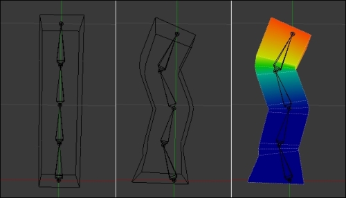
Impact of bones upon the vertices of a mesh (from left to right: bind pose, a pose, and bone-weights)
We can apply this recipe to any of our Direct3D applications. It is assumed that a class descending from the D3DApplicationBase abstract class is being used, the C# vertex structure is contained within the Vertex structure, and the C# structures for the constant buffers are defined in ConstantBuffers.cs.
We will start by updating our C# vertex structure. So go ahead and open the Vertex.cs file for editing.
- Update the member fields of the
Vertexclass to include a new property that will store the skinning information for the vertex.public Vector3 Position; public Vector3 Normal; public Color Color; public Vector2 UV; public Common.Mesh.SkinningVertex Skin; - The
SkinningVertexstructure is based upon the internal format of a CMO file, and it is included within theCommon.Meshclass. For completeness, theSkinningVertexstructure is shown in the following code snippet:[StructLayout(LayoutKind.Sequential, Pack = 1)] public struct SkinningVertex { public uint BoneIndex0; public uint BoneIndex1; public uint BoneIndex2; public uint BoneIndex3; public float BoneWeight0; public float BoneWeight1; public float BoneWeight2; public float BoneWeight3; } - Add an appropriate constructor to the
Vertexstructure. This allows us to initialize theSkinproperty we had added previously. - As always, after updating the vertex structure, we need to change the input layout that is passed to the Input Assembler (IA) stage. Within the
D3DApp.CreateDeviceDependentResourcesmethod, change the definition of the input layout to include the new vertex properties.vertexLayout = ToDispose(new InputLayout(device, vsBytecode.GetPart(ShaderBytecodePart.InputSignatureBlob), new[] { new InputElement("SV_POSITION",0,Format.R32G32B32_Float, 0,0), new InputElement("NORMAL", 0, Format.R32G32B32_Float,12,0), new InputElement("COLOR", 0, Format.R8G8B8A8_UNorm, 24,0), new InputElement("TEXCOORD", 0, Format.R32G32_Float, 28,0), // "SkinIndices" new InputElement("BLENDINDICES", 0, Format.R32G32B32A32_UInt, 36, 0), // "SkinWeights" new InputElement("BLENDWEIGHT", 0, Format.R32G32B32A32_Float, 52, 0), })); - To complete our vertex structure changes, we need to update the vertex shader and pixel shader inputs within
.ShadersCommon.hlsl. - Change the
VertexShaderInputstructure to include the two new vertex properties.uint4 SkinIndices : BLENDINDICES; // blend indices float4 SkinWeights : BLENDWEIGHT; // blend weights
- To store the list of bone influences (matrices) that will be used within the vertex shader, we need to create a new constant buffer. This buffer will be updated per armature.
// Constant buffer to hold our skin matrices for each bone.
// Note: 1024*64 = max bytes for constant buffers in SM4/5
cbuffer PerArmature : register(b3)
{
  float4x4 Bones[1024];
};
With our shader structures and constant buffers in place, we will update the vertex shader in
ShadersVS.hlslto apply the vertex skinning. - Create a new HLSL method called
SkinVertex.void SkinVertex(float4 weights, uint4 bones, inout float4 position, inout float3 normal) { // If there are skin weights apply vertex skinning if (weights.x != 0) { // Calculate the skin transform combining up to // four bone influences float4x4 skinTransform = Bones[bones.x] * weights.x + Bones[bones.y] * weights.y + Bones[bones.z] * weights.z + Bones[bones.w] * weights.w; // Apply skinning to vertex and normal position = mul(position, skinTransform); // We assume here that the skin transform includes // only uniform scaling (if any) normal = mul(normal, (float3x3)skinTransform); } - Immediately before applying the
WorldViewProjectionmatrix to the vertex position, call the newSkinVertexmethod as shown in the following code:// Apply vertex skinning if any SkinVertex(vertex.SkinWeights, vertex.SkinIndices, vertex.Position, vertex.Normal);We are done with our shaders for the moment. As we have just added a new constant buffer, we need to open
ConstantBuffers.csand make the appropriate changes. - Create a new class to store our per armature data. Note that we are using
classhere instead ofstruct, as we will be passing through theBonesarray when updating the constant buffer. This simplifies the marshalling of the structure to the Direct3D buffer, and we can initialize the array more easily.// Per armature/skeleton constant buffer public class PerArmature { // The maximum number of bones supported by the shader public const int MaxBones = 1024; public Matrix[] Bones; public PerArmature() { Bones = new Matrix[MaxBones]; } public static int Size() { return Utilities.SizeOf<Matrix>() * MaxBones; } } - Within the
D3DApp.CreateDeviceDependentResourcesmethod, initialize a newSharpDX.Direct3D11.Bufferfield member as shown in the following screenshot. We use thePerArmature.Size()method to determine the correct buffer size.perArmatureBuffer = ToDispose(new Buffer(device, ConstantBuffers.PerArmature.Size(), ResourceUsage.Default, BindFlags.ConstantBuffer, CpuAccessFlags.None, ResourceOptionFlags.None, 0));
- Now assign the buffer to the fourth vertex shader constant buffer slot.
context.VertexShader.SetConstantBuffer(3, perArmatureBuffer);
This completes the changes necessary to support vertex skinning in our vertex shader.
In order to apply the bone influences on our vertices, we must be able to pass through the bone indices and the weighting of the influence they have on the current vertex. For this purpose, we will re-use the existing structure defined within Common.Mesh.
Our implementation supports up to four bone influences per vertex. This is not only the maximum number supported by the CMO file format produced by Visual Studio, but the four bone indices and weights fit conveniently within a HLSL uint4 and float4 as you can see from the input layout we defined for the IA stage and the updated HLSL vertex structure.
As already discussed, the key component of skinning is the hierarchy of transformations that is produced from the bones of an armature. These transformations or skin matrices are implemented using the trusty old 4 x 4 affine transformation matrix. However, instead of transforming from the local object space to world space as we have done previously, we will be applying these transformations in bone space.
The transformation to bone space involves calculating the current translation and rotation for each bone, as well as its scale against its parent bone. This initial transform is now in the bind pose or rest pose space. To bring the transform into bone space, we apply the inverse bind pose matrix of the bone. The following figure shows the bones at rest (in the top-left), and in various poses for the remaining layouts.
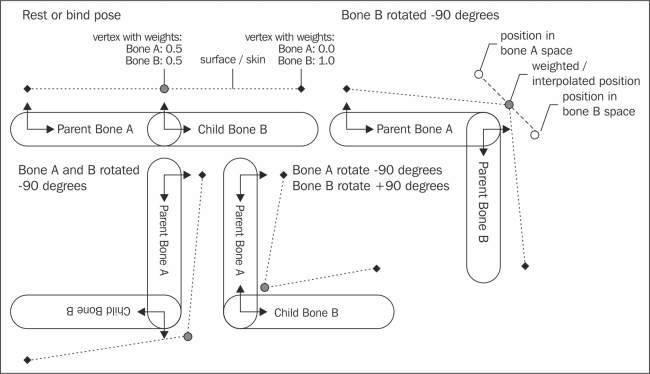
Blending of bone influences upon a vertex, and relationship between parent/child bones
This resulting skin matrix for each bone is what we are storing in the PerArmature constant buffer, and it is the matrix that we refer to within the vertex shader.
Within the vertex shader, we blend the bone influences together based upon their weight. The previous figure shows how the central vertex is influenced equally by the two bones, by using a weighting of 0.5 for each bone. The following pseudocode shows how the final transform matrix for this vertex would be calculated from the skin matrices of bone A and B.
float4x4 transform = Bones[A] * 0.5 +
  Bones[B] * 0.5;
In order to reduce the memory bandwidth, the number of bones should be reduced to a number that reflects more realistically the maximum number of bones within the models used (for example, between 64 and 100). The value of 1024 is used in this recipe to highlight the fact that this is the maximum number of 4 x 4 matrices that can be stored within a constant buffer in Shader Model 4/5 (or 65,536 bytes). In contrast, Shader Model 3 supports 256 constant float registers that can hold a single float4 component, or a maximum of sixty-four 4 x 4 matrices. This is shared between other floating point data. So, the actual number available would be less.
Note
There are tricks to increase the number of bones, such as using 4 x 3 matrices, as bones rarely require non-affine transformations. For DirectX 11 class hardware, there is probably no need; although, perhaps on some mobile devices or if you must support older hardware, it may still be something to consider.
With the armature's skin matrices in place, we can apply the vertex skinning within the vertex shader. For each of the bone influences (specified in SkinIndices), the skin transform matrix is retrieved and multiplied by the bone-weight (stored in SkinWeights). These four matrices are then added together to determine the final skin transform for this vertex.
float4x4 skinTransform = Bones[bones.x] * weights.x +
  Bones[bones.y] * weights.y +
  Bones[bones.z] * weights.z +
  Bones[bones.w] * weights.w;
// Apply skinning to vertex and normal
position = mul(position, skinTransform);
normal = mul(normal, (float3x3)skinTransform);
We then apply the skin transform to the vertex position and vertex normal. The normal transformation presented here will only work if the bone matrices always contain uniform scaling. For this to work with non-uniform scaling, it requires the usage of an inverse transpose of the matrix as described in the Preparing the vertex and constant buffers for material and lighting recipe in Chapter 3, Rendering Meshes.
If the first bone has a weight of zero, we are skipping this process. This is important because we are using this vertex shader for meshes whether or not they have any bones. A very small performance improvement can possibly be gained by splitting the vertex shader into two and choosing which shader to use on the CPU per mesh instead of making the decision within a single vertex shader for each vertex. There is, however, a performance overhead when switching shaders; so your results may vary.
The result of applying a skin matrix of zero upon all of our vertices will place them all at the origin. In the case of triangle primitives, this will result in no output. This symptom can indicate that the PerArmature constant buffer hasn't been updated correctly.
Performing vertex skinning results in a constant per-vertex performance hit. Therefore, it is desirable to have as few vertices as possible in large scenes that have multiple armatures.
A common technique of getting around the limitations of a lower maximum bone count on older hardware was implementing bone partitioning, whereby the mesh is broken up into smaller parts that share the same subset of bones. Each part is then drawn separately.