13.7. DERIVATION OF EQUATIONS FOR COUNTERCURRENT AND COCURRENT FLOW FOR GAS SEPARATION FOR MEMBRANES
13.7A. Concentration Gradients in Membranes
1. Dense-phase membrane
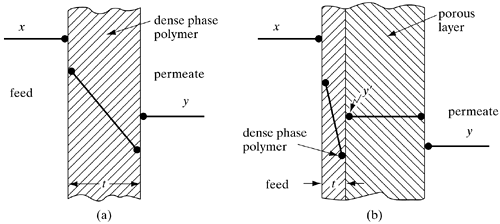
In gas separation using a dense-phase symmetrical polymer membrane, the solute diffuses through the high-pressure-side gas film to the membrane surface. Then it dissolves in the membrane. At the interface equilibrium occurs. The solute then diffuses through the solid membrane, and finally diffuses through the gas film. The gas film resistances are quite small and can be neglected (N1). In Fig. 13.7-1a the concentration profiles are shown. The concentration y in the flowing bulk gas phase is the same as y at the interface of the dense polymer and depends on the flow pattern of the permeate phase.
Figure 13.7-1. Concentration profiles in membranes. (a) dense-phase symmetrical membranes, (b) asymmetric membrane.

2. Asymmetric membrane
As shown in Fig. 13.7-1b, the membrane includes a very thin, dense polymer membrane which is about 0.1 to 1 μm thick (M5, P7) and a very thick porous layer 50–200 μm thick. A typical hollow-fiber membrane for air separation has an ID of 95 μm and an OD of 135 μm, with a wall thickness of 20 μm.
The concentration gradient in the thin dense polymer phase is similar to that for the symmetrical membrane. However, the concentration y of component A in the bulk permeate gas phase is not the same as y' at the surface of the thin dense polymer layer. The concentration y of the bulk gas permeate stream depends on the flow pattern and material balances. Also, the value of y can be greater or less than y'.
The porous layer is so open that there is assumed to be little or no resistance to the flow and y' is constant along this path. Hence, it is assumed that there is no penetration or mixing of the bulk gas phase y inside the porous layer.
13.7B. Derivation of Equations for Countercurrent Flow in Dense-Phase Symmetric Membranes
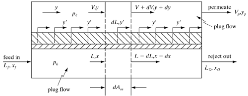
A flow diagram for this countercurrent-flow model is given in Fig. 13.7-2, where both streams are in plug flow. The derivation follows that given by others (B1, N1, P4, W5).
Figure 13.7-2. Flow diagram for the countercurrent-flow model with dense-phase symmetric membrane.

Making a total material balance,
Equation 13.7-1
![]()
where Lf is total feed flow rate, cm3 (STP)/s, Lo is outlet nonpermeate (reject) flow rate, cm3 (STP)/s, and Vp is outlet permeate flow rate, cm3 (STP)/s. The rates of permeation of A and in B in a binary mixture are similar to Eqs. (13.4-3) and (13.4-4):
Equation 13.7-2
![]()
Equation 13.7-3
![]()
where ![]() is permeability of A, cm3 (STP) · cm/(s · cm2 · cm Hg); VA is flow rate of A in permeate, cm3 (STP)/s; Am is membrane area, cm2; ph is total pressure in the high-pressure side, cm Hg; and pt is total pressure in low-pressure side, cm Hg.
is permeability of A, cm3 (STP) · cm/(s · cm2 · cm Hg); VA is flow rate of A in permeate, cm3 (STP)/s; Am is membrane area, cm2; ph is total pressure in the high-pressure side, cm Hg; and pt is total pressure in low-pressure side, cm Hg.
The flux of A out of the element with area dAm is
Equation 13.7-4
![]()
The flux of B is
Equation 13.7-5
![]()
Making a total balance on the reject stream for area dAm,
Equation 13.7-6
![]()
This gives
Equation 13.7-7
![]()
Making a balance on A for area dAm,
Equation 13.7-8
![]()
Rearranging,
Equation 13.7-9
![]()
Substituting Eq. (13.7-7) into (13.7-9),
Equation 13.7-10
![]()
Making a total balance on permeate stream for area dAm,
Equation 13.7-11
![]()
This gives
Equation 13.7-12
![]()
Making a balance on A for area dAm,
Equation 13.7-13
![]()
Rearranging,
Equation 13.7-14
![]()
Substituting Eq. (13.7-12) into (13.7-14),
Equation 13.7-15
![]()
To eliminate the variables L and V, an overall balance is made for the area dAm and the reject outlet stream:
Equation 13.7-16
![]()
Equation 13.7-17
![]()
To eliminate V, V from Eq. (13.7-16) is substituted into (13.7-17) and solved for L:
Equation 13.7-18
![]()
To eliminate L, L from Eq. (13.7-16) is substituted into (13.7-17) and solved for V:
Equation 13.7-19
![]()
Substituting Eq. (13.7-18) into (13.7-10),
Equation 13.7-20
![]()
Substituting Eqs. (13.7-4) and (13.7-5) into (13.7-20),
Equation 13.7-21

Rearranging,
Equation 13.7-22
![]()
where r = pl/ph and α* = (![]() /t)/(
/t)/(![]() /t).
/t).
In a similar manner, substituting Eq. (13.7-19) into (13.7-15),
Equation 13.7-23
![]()
Again, substituting Eqs. (13.7-4) and (13.7-5) into (13.7-23) and rearranging,
Equation 13.7-24
![]()
Dividing Eq. (13.7-24) by (13.7-22),
Equation 13.7-25
![]()
Inverting Eq. (13.7-22),
Equation 13.7-26

13.7C. Solution of Countercurrent Flow Equations in Dense-Phase Symmetric Membranes
At the outlet of the residue stream of composition xo, the permeate y' and xo are related by Eq. (13.4-6), repeated here as Eq. (13.7-27), where yp = y':
Equation 13.7-27
![]()
The solution to this quadratic equation is given as Eq. (13.4-7).
In order to solve Eqs. (13.7-25) and (13.7-26), the following procedure can be used, where xo is known or set:
1. | |
2. | To integrate Eq. (13.7-25), the value of (dy/dx) at x = xo must be calculated. However, this value is indeterminate since the denominator is zero. Using L'Hopital's rule (N1, P4, R1) the numerator is differentiated with respect to x and the denominator with respect to x and the value of y is set as y' to give Equation 13.7-28 |
3. | Starting at the residual end at xo, Eq. (13.7-25) is integrated numerically to give the y-versus-x relationship and yp (P4, R1). |
4. | The relationship of y versus x is substituted into Eq. (13.7-26), which is integrated from xf to xo to obtain the area Am. |
5. | Substituting into the material-balance Eqs. (13.4-8) and (13.4-2), the cut or fraction of feed permeated, θ, is calculated (N1, Rl, W5). |
6. | If θ is set and xo is unknown, the solution is trial and error. The value of xo is assumed and the integration of Eq. (13.7-25) is performed to obtain yp. Then xo is calculated from Eq. (13.4-9). This is repeated until the assumed and calculated values of xo agree. |
13.7D. Derivation of Equations for Countercurrent Flow in Asymmetric Membranes
The flow diagram for this countercurrent-flow model is shown in Fig. 13.7-3, where both streams are in plug flow. The permeate y' leaving the membrane differs from the symmetric-membrane case and is not the same as the bulk phase concentration y at this point. This is also shown in Fig. 13.7-1b.
Figure 13.7-3. Flow diagram for countercurrent flow with asymmetric membrane.

The flux of A out of the element with area dAm is
Equation 13.7-29
![]()
where y' is given by Eq. (13.7-30), which is similar to Eqs. (13.7-27) and (13.4-6):
Equation 13.7-30
![]()
The flux of B is
Equation 13.7-31
![]()
Equations (13.7-29) and (13.7-31) differ from Eqs. (13.7-4) and (13.7-5) for the symmetric membrane in that y' is used instead of y in the terms for concentration difference.
The rest of the derivation is identical to that for the dense-phase symmetric membrane (N1, R1). The final equations are
Equation 13.7-32
![]()
Equation 13.7-33

Inverting Eq. (13.7-32),
Equation 13.7-34

Equations (13.7-27) for y' and (13.7-28) for (dy/dx) at x = xo for symmetric membranes are also applicable here for asymmetric membranes. The method of solution for the above equations is similar to that for symmetric membranes.
13.7E. Derivation of Equations for Cocurrent Flow in Asymmetric Membranes
For cocurrent flow, the cocurrent model is shown in Fig. 13.7-4. The derivation uses Eqs. (13.7-29)-(13.7-31) as before. Proceeding in a manner similar to the countercurrent case, the final equations are (N1, P4, R1):
Equation 13.7-35
![]()
Equation 13.7-36

Figure 13.7-4. Flow diagram for cocurrent flow with asymmetric membrane.

The method of solution is similar to that for countercurrent flow. Integration of Eq. (13.7-35) is started at the feed inlet, where y' is determined by using xf instead of xo in Eq. (13.7-27). Then, using Eq. (13.7-28) with xf instead of xo, (dy/dx) at x = xf is calculated. This is then used to integrate Eq. (13.7-35) starting at the feed end, where x = xf. Finally, Eq. (13.7-36) is integrated to obtain Am.
13.7F. Effects of Processing Variables on Gas Separation
1. Effects of pressure ratio and separation factor on recovery
Using the Weller-Steiner Eq. (13.4-6) for the complete-mixing model, the effects of pressure ratio, ph/pl, and separation factor, α*, on permeate purity can be determined for a fixed feed composition. Figure 13.7-5 is a plot of this equation for a feed concentration of 30% (S7). For symmetric and asymmetric membranes, this equation can be expected to provide estimates of product purity and trends for conditions of low to modest recovery in all types of models, including complete-mixing, cross-flow, and countercurrent.
Figure 13.7-5. Effects of separation factor and pressure ratio on permeate purity. (Feed xf = 0.30.) [From "Membranes Separate Gases Selectively," by D. J. Stookey, C. J. Patton, and G. L. Malcolm, Chem. Eng. Progr., 82(11), 36(1986). Reproduced by permission of the American Institute of Chemical Engineers.]

Figure 13.7-5 shows that above an a* of 20, the product purity is not greatly affected. Also, above a pressure ratio of about 6, this ratio has a diminishing effect on product purity.
If liquids are present in the gas separation process, a liquid film can increase the membrane resistance markedly. Liquids can also damage the membrane by chemical action or by swelling or softening. If water vapor is present in the gas streams, the dew point may be reached in the residue product and liquid may condense. Condensation of hydrocarbons must also be avoided.
2. Effects of process flow patterns on separation in symmetric membranes
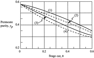
Detailed parametric studies have been done by various investigators (P4, P5, W5) for binary systems. They compared the four flow patterns of complete mixing, cross-flow, cocurrent, and countercurrent flow. In Fig. 13.7-6 (W5) the permeate concentration is shown plotted versus stage cut, θ, for a feed of air (xf = 0.209 for oxygen) with α* = 10 and ph/pl = 5. It is shown that, as expected, the countercurrent flow pattern gives the best separation. The other patterns—cross-flow, cocurrent, and complete mixing—give lower separations in descending order. Note that when the stage cut θ = 0, all flow patterns are equivalent to the complete mixing model and give the same permeate composition. Also, at θ = 1.00, all patterns again give the same value of yp = 0.209, which is also the feed composition.
Figure 13.7-6. Effect of flow pattern in symmetric membranes. Operating conditions for air are as follows: xf
= 0.209,
 = 10, ph/pl
= 380 cm Hg/76 cm Hg = 5.
 = 500 × 10-10
cm3
(STP) · cm/s · cm2
· cm Hg. (1) countercurrent flow, (2) cross-flow, (3) cocurrent flow, (4) complete mixing (W5). [Reprinted from W. P. Walawender and S. A. Stern, Sep. Sci., 7, 553 (1972). By courtesy of Marcel Dekker, Inc.]

The required membrane areas for the same process conditions and air feed versus stage cut were also determined (W5). The areas for all four types of flow pattern were shown to be within about 10% of each other. The countercurrent and cross-flow patterns give the lowest area required.
3. Effects of process flow patterns on separation in asymmetric membranes
Calculations using the mathematical models for asymmetric membranes give virtually identical performances for cocurrent and countercurrent flow (G1, P2, P6). The porous support prevents mixing of the bulk permeate concentration and the skin surface concentration y' as shown in Fig. 13.7-1b. Hence, the direction of the bulk flow permeate stream has no effect. Experimental tests using helium recovery from natural gas (P2, P6), nitrogen recovery from air (G1), and helium from nitrogen (G1) show that the experimental data and the model predictions agree quite well.
4. Effect of pressure drop on separations in asymmetric membranes
In hollow-fiber membranes (N1), an appreciable pressure drop can occur for flow inside long tubes or for tubes with very small inside diameters. In the shell side the pressure drop is generally very small and is neglected. Pressure drop in the tubes is always detrimental to the separation. For feed inside the tubes, the actual average feed pressure will be less than the inlet feed pressure. If the permeate flow is inside the tubes, then the actual average permeate pressure will be higher than the permeate outlet pressure. In both of these cases, the driving force for permeation is reduced and less separation occurs.
To reduce these pressure effects, where the stage cut θ is small, giving a low permeate flow rate, it is preferable to have the large feed flow rate in the shell, where the pressure drop is small. For a high stage cut, the feed should be inside the tubes, where most of the feed permeates into the shell.
Using the model equations, the pressure drop inside the tubes can be accounted for by using the Hagen-Poisseuille equation (2.10-2) for laminar flow:
Equation 2.10-2
![]()
where z2 - z1 is total length. Writing this for a differential length dz cm and a dph in Pascals,
Equation 13.7-37
![]()
Converting the feed flow rate L cm3/s at Ts and ps (STP) to the actual velocity ν at T and ph,
Equation 13.7-38
![]()
where NT is the number of tubes in parallel. The average viscosity μ can be approximated by using the average mole fraction of the feed and the residual outlet. The average μ is then the sum of the mole fractions of each component times the viscosity of the pure gases. The final equation is (G1, N1, P2)
Equation 13.7-39
![]()
The area Am can be related to z by dAm = πDNT dz. This then relates dAm to dph. In integrating the model equations, a constant (uniform) ph is first assumed (G1, P2, P7). This gives the relation between y and x and Am. Then, using the material-balance equation (13.7-18) between L and y and x, equation (13.7-39) is used to generate a new pressure profile. This process is then repeated.
