2.6. OVERALL MASS BALANCE AND CONTINUITY EQUATION
2.6A. Introduction and Simple Mass Balances
In fluid dynamics fluids are in motion. Generally, they are moved from place to place by means of mechanical devices such as pumps or blowers, by gravity head, or by pressure, and flow through systems of piping and/or process equipment. The first step in the solution of flow problems is generally to apply the principles of the conservation of mass to the whole system or to any part of the system. First, we will consider an elementary balance on a simple geometry, and later we shall derive the general mass-balance equation.
Simple mass or material balances were introduced in Section 1.5, where
Equation 1.5-1
![]()
Since, in fluid flow, we are usually working with rates of flow and usually at steady state, the rate of accumulation is zero and we obtain
Equation 2.6-1
![]()
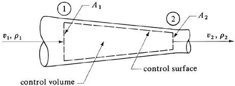
In Fig. 2.6-1 a simple flow system is shown, where fluid enters section 1 with an average velocity ν1 m/s and density ρ1 kg/m3. The cross-sectional area is A1 m2. The fluid leaves section 2 with average velocity ν2. The mass balance, Eq. (2.6-1), becomes
Equation 2.6-2
![]()
Figure 2.6-1. Mass balance on flow system.

where m = kg/s. Often, νρ is expressed as G = νρ, where G is mass velocity or mass flux in kg/s · m2. In English units, ν is in ft/s, ρ in lbm/ft3, A in ft2, m in lbm/s, and G in lbm/s · ft2.
EXAMPLE 2.6-1. Flow of Crude Oil and Mass BalanceA petroleum crude oil having a density of 892 kg/m3 is flowing through the piping arrangement shown in Fig. 2.6-2 at a total rate of 1.388 × 10⁻³ m3/s entering pipe 1. Figure 2.6-2. Piping arrangement for Example 2.6-1.
The flow divides equally in each of pipes 3. The steel pipes are schedule 40 pipe (see Appendix A.5 for actual dimensions). Calculate the following, using SI units:
Solution: From Appendix A.5, the dimensions of the pipes are as follows: 2-in. pipe: D1 (ID) = 2.067 in.; cross-sectional area
The total mass flow rate is the same through pipes 1 and 2 and is
Since the flow divides equally in each of pipes 3,
For part (b), using Eq. (2.6-2) and solving for v,
For part (c),
|
2.6B. Control Volume for Balances
The laws for the conservation of mass, energy, and momentum are all stated in terms of a system; these laws give the interaction of a system with its surroundings. A system is defined as a collection of fluid of fixed identity. However, in flow of fluids, individual particles are not easily identifiable. As a result, attention is focused on a given space through which the fluid flows rather than on a given mass of fluid. The method used, which is more convenient, is to select a control volume, which is a region fixed in space through which the fluid flows.
In Fig. 2.6-3 the case of a fluid flowing through a conduit is shown. The control surface shown as a dashed line is the surface surrounding the control volume. In most problems part of the control surface will coincide with some boundary, such as the wall of the conduit. The remaining part of the control surface is a hypothetical surface through which the fluid can flow, shown as point 1 and point 2 in Fig. 2.6-3. The control-volume representation is analogous to the open system of thermodynamics.
Figure 2.6-3. Control volume for flow through a conduit.

2.6C. Overall Mass-Balance Equation
In deriving the general equation for the overall balance of the property mass, the law of conservation of mass may be stated as follows for a control volume where no mass is being generated.
Equation 2.6-3

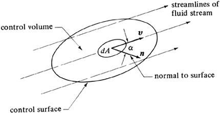
We now consider the general control volume fixed in space and located in a fluid flow field, as shown in Fig. 2.6-4. For a small element of area dA m2 on the control surface, the rate of mass efflux from this element = (ρν)(dA cos α), where (dA cos α) is the area dA projected in a direction normal to the velocity vector ν, α is the angle between the velocity vector ν and the outward-directed unit normal vector n to dA, and ρ is the density in kg/m3. The quantity ρν has units of kg/s · m2 and is called a flux or mass velocity G.
Figure 2.6-4. Flow through a differential area dA on a control surface.

From vector algebra we recognize that (ρν)(dA cos α) is the scalar or dot product ρ(v · n) dA. If we now integrate this quantity over the entire control surface A, we have the net outflow of mass across the control surface, or the net mass efflux in kg/s from the entire control volume V:
Equation 2.6-4

We should note that if mass is entering the control volume, that is, flowing inward across the control surface, the next efflux of mass in Eq. (2.6-4) is negative, since α > 90° and cos α is negative. Hence, there is a net influx of mass. If α < 90°, there is a net efflux of mass.
The rate of accumulation of mass within the control volume V can be expressed as follows:
Equation 2.6-5

where M is the mass of fluid in the volume in kg. Substituting Eqs. (2.6-4) and (2.6-5) into (2.6-3), we obtain the general form of the overall mass balance:
Equation 2.6-6

The use of Eq. (2.6-6) can be shown for a common situation of steady-state one-dimensional flow, where all the flow inward is normal to A1 and outward normal to A2, as shown in Fig. 2.6-3. When the velocity ν2 leaving (Fig. 2.6-3) is normal to A2, the angle α2 between the normal to the control surface and the direction of the velocity is 0°, and cos α2 = 1.0. Where ν1 is directed inward, α1 > π/2, and for the case in Fig. 2.6-3, α1 is 180° (cos α1 = −1.0). Since α2 is 0° and α1 is 180°, using Eq. (2.6-4),
Equation 2.6-7

For steady state, dM/dt = 0 in Eq. (2.6-5), and Eq. (2.6-6) becomes
Equation 2.6-2
![]()
which is Eq. (2.6-2), derived earlier.
In Fig. 2.6-3 and Eqs. (2.6-3)–(2.6-7) we were not concerned with the composition of any of the streams. These equations can easily be extended to represent an overall mass balance for component i in a multicomponent system. For the case shown in Fig. 2.6-3, we combine Eqs. (2.6-5), (2.6-6), and (2.6-7), add a generation term, and obtain
Equation 2.6-8
![]()
where mi2 is the mass flow rate of component i leaving the control volume and Ri is the rate of generation of component i in the control volume in kg per unit time. (Diffusion fluxes are neglected here or are assumed negligible.) In some cases, of course, Ri = 0 for no generation. Often it is more convenient to use Eq. (2.6-8) written in molar units.
EXAMPLE 2.6-2. Overall Mass Balance in Stirred TankInitially, a tank holds 500 kg of salt solution containing 10% salt. At point (1) in the control volume in Fig. 2.6-5, a stream enters at a constant flow rate of 10 kg/h containing 20% salt. A stream leaves at point (2) at a constant rate of 5 kg/h. The tank is well stirred. Derive an equation relating the weight fraction wA of the salt in the tank at any time t in hours. Figure 2.6-5. Control volume for flow in a stirred tank for Example 2.6-2.
Solution: First we make a total mass balance using Eq. (2.6-7) for the net total mass efflux from the control volume: Equation 2.6-9
From Eq. (2.6-5), where M is total kg of solution in control volume at time t, Equation 2.6-5
Substituting Eqs. (2.6-5) and (2.6-9) into (2.6-6), and then integrating, Equation 2.6-10
Equation 2.6-11
Equation (2.6-11) relates the total mass M in the tank at any time to t. Next, making a component A salt balance, let wA = weight fraction of salt in tank at time t and also the concentration in the stream m2 leaving at time t. Again using Eq. (2.6-7) but for a salt balance, Equation 2.6-12
Using Eq. (2.6-5) for a salt balance, Equation 2.6-13
Substituting Eqs. (2.6-12) and (2.6-13) into (2.6-6), Equation 2.6-14
Substituting the value for M from Eq. (2.6-11) into (2.6-14), separating variables, integrating, and solving for wA, Equation 2.6-15
Equation 2.6-16
Note that Eq. (2.6-8) for component i could have been used for the salt balance with Ri = 0 (no generation). |
2.6D. Average Velocity to Use in Overall Mass Balance
In solving the case in Eq. (2.6-7), we assumed a constant velocity ν1 at section 1 and constant ν2 at section 2. If the velocity is not constant but varies across the surface area, an average or bulk velocity is defined by
Equation 2.6-17

for a surface over which ν is normal to A and the density ρ is assumed constant.
EXAMPLE 2.6-3. Variation of Velocity Across Control Surface and Average VelocityFor the case of incompressible flow (ρ is constant) through a circular pipe of radius R, the velocity profile is parabolic for laminar flow as follows: Equation 2.6-18
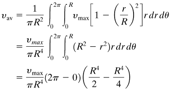
where νmax is the maximum velocity at the center where r = 0 and ν is the velocity at a radial distance r from the center. Derive an expression for the average or bulk velocity νav to use in the overall mass-balance equation. Solution: The average velocity is represented by Eq. (2.6-17). In Cartesian coordinates dA is dx dy. However, using polar coordinates, which are more appropriate for a pipe, dA = rdrdθ, where θ is the angle in polar coordinates. Substituting Eq. (2.6-18), dA = rdrdθ, and A = πR2 into Eq. (2.6-17) and integrating, Equation 2.6-19
Equation 2.6-20
|
In this discussion overall or macroscopic mass balances were made because we wish to describe these balances from outside the enclosure. In this section on overall mass balances, some of the equations presented may have seemed quite obvious. However, the purpose was to develop the methods which should be helpful in the next sections. Overall balances will also be made on energy and momentum in the next sections. These overall balances do not tell us the details of what happens inside. However, in Section 2.9 a shell momentum balance will be made in order to obtain these details, which will give us the velocity distribution and pressure drop. To further study these details of the processes occurring inside the enclosure, differential balances rather than shell balances can be written; these are discussed later in Sections 3.6–3.9 on differential equations of continuity and momentum transfer, Sections 5.6 and 5.7 on differential equations of energy change and boundary-layer flow, and Section 7.5B on differential equations of continuity for a binary mixture.


