4.15. NUMERICAL METHODS FOR STEADY-STATE CONDUCTION IN TWO DIMENSIONS
4.15A. Analytical Equation for Conduction
In Section 4.4 we discussed methods for solving two-dimensional heat-conduction problems using graphical procedures and shape factors. In this section we consider analytical and numerical methods.
The equation for conduction in the x direction is as follows:
Equation 4.15-1
![]()
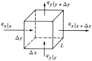
Now we shall derive an equation for steady-state conduction in two directions x and y. Referring to Fig. 4.15-1, a rectangular block Δx by Δy by L is shown. The total heat input to the block is equal to the output:
Equation 4.15-2
![]()
Figure 4.15-1. Steady-state conduction in two directions.

Now, from Eq. (4.15-1),
Equation 4.15-3

Writing similar equations for the other three terms and substituting into Eq. (4.15-2),
Equation 4.15-4
Dividing through by Δx ΔyL and letting Δx and Δy approach zero, we obtain the final equation for steady-state conduction in two directions:
Equation 4.15-5

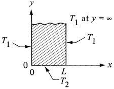
This is called the Laplace equation.. There are a number of analytical methods for solving this equation. In the method of separation of variables, the final solution is expressed as an infinite Fourier series (H1, G2, K1). We consider the case shown in Fig. 4.15-2. The solid is called a semi-infinite solid since one of its dimensions is ∞. The two edges or boundaries at x = 0 and x = L are held constant at T1 K. The edge at y = 0 is held at T2. And at y = ∞, T = T1. The solution relating T to position y and x is
Equation 4.15-6

Figure 4.15-2. Steady-state heat conduction in two directions in a semi-infinite plate.

Other analytical methods are available and are discussed in many texts (C2, H1, G2, K1). A large number of such analytical solutions have been given in the literature. However, there are many practical situations where the geometry or boundary conditions are too complex for analytical solutions, so that finite-difference numerical methods are used. These are discussed in the next section.
4.15B. Finite-Difference Numerical Methods
1. Derivation of the method
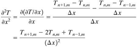
Since the advent of fast digital computers, solutions to many complex two-dimensional heat-conduction problems by numerical methods are readily possible. In deriving the equations we can start with the partial differential equation (4.15-5). Setting up the finite difference of ∂·2T/∂·x2,
Equation 4.15-7

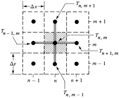
where the index m stands for a given value of y, m + 1 stands for y + 1 Δy, and n is the index indicating the position of T on the x scale. This is shown in Fig. 4.15-3. The two-dimensional solid is divided into squares. The solid inside a square is imagined to be concentrated at the center of the square, and this concentrated mass is a "node." Each node is imagined to be connected to the adjacent nodes by a small conducting rod as shown.
Figure 4.15-3. Temperatures and arrangement of nodes for two-dimensional steady-state heat conduction.

The finite difference of ∂·2T/∂·y2 is written in a similar manner:
Equation 4.15-8

Substituting Eqs. (4.15-7) and (4.15-8) into Eq. (4.15-5) and setting Δx = Δy,
Equation 4.15-9
![]()
This equation states that the net heat flow into any point or node is zero at steady state. The shaded area in Fig. 4.15-3 represents the area on which the heat balance was made. Alternatively, Eq. (4.15-9) can be derived by making a heat balance on this shaded area. The total heat in for unit thickness is
Equation 4.15-10

Rearranging, this becomes Eq. (4.15-9). In Fig. 4.15-3 the rods connecting the nodes act as fictitious heat-conducting rods.
To use the numerical method, Eq. (4.15-9) is written for each node or point. Hence, for N unknown nodes, N linear algebraic equations must be written and the system of equations solved for the various node temperatures. For a hand calculation using a modest number of nodes, the iteration method can be used to solve the system of equations.
2. Iteration method of solution
In using the iteration method, the right-hand side of Eq. (4.15-9) is set equal to a residual ![]() :
:
Equation 4.15-11
![]()
Since ![]() = 0 at steady state, solving for Tn,m in Eq. (4.15-11) or (4.15-9),
= 0 at steady state, solving for Tn,m in Eq. (4.15-11) or (4.15-9),
Equation 4.15-12

Equations (4.15-11) and (4.15-12) are the final equations to be used. Their use is illustrated in the following example.
EXAMPLE 4.15-1. Steady-State Heat Conduction in Two DirectionsFigure 4.15-4 shows a cross section of a hollow rectangular chamber with inside dimensions 4 × 2 m and outside dimensions 8 × 8 m. The chamber is 20 m long. The inside walls are held at 600 K and the outside at 300 K. The k is 1.5 W/m · K. For steady-state conditions find the heat loss per unit chamber length. Use grids 1 ×‐ 1 m. Figure 4.15-4. Square grid pattern for Example 4.15-1.
Solution: Since the chamber is symmetrical, one-fourth of the chamber (shaded part) will be used. Preliminary estimates will be made for the first approximation: T1,2 = 450 K, T2,2 = 400, T3,2 = 400, T3,3 = 400, T3,4 = 450, T3,5 = 500, T4,2 = 325, T4,3 = 350, T4,4 = 375, and T4,5 = 400. Note that T0,2 = T2,2, T3,6 = T3,4, and T4,6 = T4,4 by symmetry. To start the calculation, one can select any interior point, but it is usually better to start near a boundary. Using T1,2, we calculate the residual
Hence, T1,2 is not at steady state. Next, we set
This new value of T1,2 of 425 K will replace the old one of 450 and be used to calculate the other nodes. Next,
Setting
Continuing for all the rest of the interior nodes,
Using Eq. (4.15-12), T3,2 = 364,
Having completed one sweep across the grid map, we can start a second approximation, using, of course, the new values calculated. We can start again with T1,2 or we can select the node with the largest residual. Starting with T1,2 again,
This is continued until the residuals are as small as desired. The final values are as follows:
To calculate the total heat loss from the chamber per unit chamber length, we use Fig. 4.15-5. For nodes T2,4 to T3,4 with Δx = Δy and 1 m deep, Equation 4.15-13
Figure 4.15-5. Drawing for calculation of total heat conduction.
The heat flux for nodes T2,5 to T3,5 and for T1,3 to T1,2 should be multiplied by Equation 4.15-14
Also, the total heat conducted can be calculated using the nodes at the outside, as shown in Fig. 4.15-5. This gives qII = 3430 W. The average value is
|
If a larger number of nodes, that is, a smaller grid size, is used, a more accurate solution can be obtained. Using a grid size of 0.5 m instead of 1.0 m for Example 4.15-1, a qav of 3250 W is obtained. If a very fine grid is used, more accuracy can be obtained, but a digital computer would be needed for the large number of calculations. Matrix methods are also available for solving a set of simultaneous equations on a computer. The iteration method used here is often called the Gauss-Seidel method. The simplest and most convenient method is to use a spreadsheet calculation with a computer. This avoids the complication of using complex matrix methods and so forth.
3. Equations for other boundary conditions
In Example 4.15-1 the conditions at the boundaries were such that the node points were known and constant. For the case where there is convection at the boundary to a constant temperature T∞, a heat balance on the node n, m in Fig. 4.15-6a is as follows, where heat in = heat out (K1):
Equation 4.15-15

Figure 4.15-6. Other types of boundary conditions: (a) convection at a boundary, (b) insulated boundary, (c) exterior corner with convective boundary, (d) interior corner with convective boundary.

Setting Δx = Δy, rearranging, and setting the resultant equation = ![]() residual, the following results:
residual, the following results:
In a similar manner, for the cases in Fig. 4.15-6:
For curved boundaries and other types of boundaries, see (C3, K1). To use Eqs. (4.15-16)–(4.15-19), the residual ![]() is first obtained using the proper equation. Then
is first obtained using the proper equation. Then ![]() is set equal to zero and Tn,m solved for in the resultant equation.
is set equal to zero and Tn,m solved for in the resultant equation.


