8.5. CALCULATION METHODS FOR MULTIPLE-EFFECT EVAPORATORS
8.5A. Introduction
In evaporation of solutions in a single-effect evaporator, a major cost is the cost of the steam used to evaporate the water. A single-effect evaporator is wasteful in terms of steam costs, since the latent heat of the vapor leaving the evaporator is usually not used. To reduce this cost, multiple-effect evaporators are used, which recover the latent heat of the vapor leaving and reuse it.
A three-effect evaporator, discussed briefly in Section 8.2B, is shown in Fig. 8.2-3. In this system each effect in itself acts as a single-effect evaporator. Raw steam is used as the heating medium to the first effect, which is boiling at temperature T1 and pressure P1. The vapor removed from the first effect is then used as the heating medium, condensing in the second effect and vaporizing water at temperature T2 and pressure P2 in this effect. To transfer heat from the condensing vapor to the boiling liquid in this second effect, the boiling temperature T2 must be less than the condensing temperature. This means that the pressure P2 in the second effect is lower than P1 in the first effect. In a similar manner, vapor from the second effect is condensed in heating the third effect. Hence, pressure P3 is less than P2. If the first effect is operating at 1 atm abs pressure, the second and third effects will be under vacuum.
In the first effect, raw, dilute feed is added and is partly concentrated. Then this partly concentrated liquid (Fig. 8.2-3) flows to the second evaporator in series, where it is further concentrated. This liquid from the second effect flows to the third effect for final concentration.
When a multiple-effect evaporator is at steady-state operation, the flow rates and rate of evaporation in each effect are constant. The pressures, temperatures, and internal flow rates are automatically kept constant by the steady-state operation of the process itself. To change the concentration in the final effect, the feed rate to the first effect must be changed. The overall material balance made over the whole system and over each evaporator itself must be satisfied. If the final solution is too concentrated, the feed rate must be increased, and vice versa. Then the final solution will reach a new steady state at the desired concentration.
8.5B. Temperature Drops and Capacity of Multiple-Effect Evaporators
1. Temperature drops in multiple-effect evaporators
The amount of heat transferred per hour in the first effect of a triple-effect evaporator with forward feed as in Fig. 8.2-3 will be
Equation 8.5-1
![]()
where ΔT1 is the difference between the condensing steam and the boiling point of the liquid, Ts – T1. Assuming that the solutions have no boiling-point rise and no heat of solution and neglecting the sensible heat necessary to heat the feed to the boiling point, approximately all the latent heat of the condensing steam appears as latent heat in the vapor. This vapor then condenses in the second effect, giving up approximately the same amount of heat:
Equation 8.5-2
![]()
This same reasoning holds for q3. Since q1 = q2 = q3, then, approximately,
Equation 8.5-3
![]()
In commercial practice the areas in all effects are usually equal and
Equation 8.5-4
![]()
Hence, the temperature drops ΔT in a multiple-effect evaporator are approximately inversely proportional to the values of U. Calling ∑ ΔT as follows for no boiling-point rise,
Equation 8.5-5
![]()
Note that ΔT1 °C = ΔT1 K, ΔT2 °C = ΔT2 K, and so on. Since ΔT1 is proportional to 1/U1, then
Equation 8.5-6
![]()
Similar equations can be written for ΔT2 and ΔT3.
2. Capacity of multiple-effect evaporators
A rough estimate of the capacity of a three-effect evaporator compared to a single-effect can be obtained by adding the value of q for each evaporator:
Equation 8.5-7
![]()
If we make the assumptions that the value of U is the same in each effect and that the values of A are equal, Eq. (8.5-7) becomes
Equation 8.5-8
![]()
where ΔT = ∑ ΔT = ΔT1 + ΔT2 + ΔT3 = TS – T3.
If a single-effect evaporator is used with the same area A, the same value of U, and the same total temperature drop ΔT, then
Equation 8.5-9
![]()
This, of course, gives the same capacity as for the multiple-effect evaporator. Hence, the increase in steam economy obtained by using multiple-effect evaporators is obtained at the expense of reduced capacity.
8.5C. Calculations for Multiple-Effect Evaporators
In doing calculations for a multiple-effect evaporator system, the values to be obtained are usually the area of the heating surface in each effect, the kg of steam per hour to be supplied, and the amount of vapor leaving each effect, especially the last one. The given or known values are usually as follows: (1) steam pressure to the first effect, (2) final pressure in the vapor space of the last effect, (3) feed conditions and flow to the first effect, (4) the final concentration in the liquid leaving the last effect, (5) physical properties such as enthalpies and/or heat capacities of the liquid and vapors, and (6) overall heat-transfer coefficients in each effect. Usually, the areas of each effect are assumed equal.
The calculations are done using material balances, heat balances, and the capacity equations q = UA ΔT for each effect. A convenient way to solve these equations is by trial and error. The basic steps to follow are given as follows for a triple-effect evaporator.
8.5D. Step-by-Step Calculation Methods for Triple-Effect Evaporators
1. | From the known outlet concentration and pressure in the last effect, determine the boiling point in the last effect. (If a boiling-point rise is present, this can be determined from a Dühring-line plot.) |
2. | Determine the total amount of vapor evaporated by performing an overall material balance. For this first trial, apportion the total amount of vapor among the three effects. (Usually, equal amounts of vapor are produced in each effect, so that V1 = V2 = V3 is assumed for the first trial.) Make a total material balance on effects 1, 2, and 3 to obtain L1, L2, and L3. Then calculate the solids concentration in each effect by a solids balance on each effect. |
3. | Using Eq. (8.5-6), estimate the temperature drops ΔT1, ΔT2, and ΔT3 in the three effects. Any effect that has an extra heating load, such as a cold feed, requires a proportionately larger ΔT. Then calculate the boiling point in each effect. [If a boiling-point rise (BPR) in °C is present, estimate the pressure in effects 1 and 2 and determine the BPR in each of the three effects. Only a crude pressure estimate is needed, since BPR is almost independent of pressure. Then the ∑ ΔT available for heat transfer without the superheat is obtained by subtracting the sum of all three BPRs from the overall ΔT of TS – T3 (saturation). Using Eq. (8.5-6), estimate ΔT1, ΔT2, and ΔT3. Then calculate the boiling point in each effect.] |
4. | Using heat and material balances in each effect, calculate the amount vaporized and the flows of liquid in each effect. If the amounts vaporized differ appreciably from those assumed in step 2, then steps 2, 3, and 4 can be repeated using the amounts of evaporation just calculated. (In step 2 only the solids balance is repeated.) |
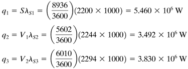
5. | Calculate the value of q transferred in each effect. Using the rate equation q = UA ΔT for each effect, calculate the areas A1, A2, and A3. Then calculate the average value Am by Equation 8.5-10
If these areas are reasonably close to each other, the calculations are complete and a second trial is not needed. If these areas are not almost equal, a second trial should be performed as follows. |
6. | To start trial 2, use the new values of L1, L2, L3, V1, V2, and V3 calculated by the heat balances in step 4 and calculate the new solids concentration in each effect by a solids balance on each effect. |
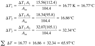
7. | Obtain new values Equation 8.5-11
The sum [If a boiling-point rise is present, determine the new BPRs in the three effects using the new concentrations from step 6. To get a new value of ∑ ΔT available for heat transfer, subtract the sum of all three BPRs from the overall ΔT. Calculate the new values of ΔT' by Eq. (8.5-11). The sum of the ΔT' values just calculated must be readjusted to the new ∑ ΔT value. Then calculate the boiling point in each effect.] Step 7 is essentially a repeat of step 3 but using Eq. (8.5-11) to obtain a better estimate of the ΔT' values. |
8. | Using the new ΔT' values from step 7, repeat the calculations starting with step 4. Two trials are usually sufficient so that the areas are reasonably close to being equal. |
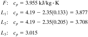
EXAMPLE 8.5-1. Evaporation of Sugar Solution in a Triple-Effect EvaporatorA triple-effect forward-feed evaporator is being used to evaporate a sugar solution containing 10 wt % solids to a concentrated solution of 50%. The boiling-point rise of the solutions (independent of pressure) can be estimated from BPR°C = 1.78x + 6.22x2 (BPR°F = 3.2x + 11.2x2), where x is wt fraction of sugar in solution (K1). Saturated steam at 205.5 kPa (29.8 psia) [121.1°C (250°F) saturation temperature] is being used. The pressure in the vapor space of the third effect is 13.4 kPa (1.94 psia). The feed rate is 22 680 kg/h (50 000 lbm/h) at 26.7°C (80°F). The heat capacity of the liquid solutions is (K1) cp = 4.19 – 2.35x kJ/kg · K (1.0 – 0.56x btu/lbm · °F). The heat of solution is considered to be negligible. The coefficients of heat transfer have been estimated as U1 = 3123, U2 = 1987, and U3 = 1136 W/m2 · K, or 550, 350, and 200 btu/h · ft2 · °F. If each effect has the same surface area, calculate the area, the steam rate used, and the steam economy. Solution: The process flow diagram is given in Fig. 8.5-1. Following the eight steps outlined, the calculations are as follows:
Figure 8.5-1. Flow diagram for triple-effect evaporation for Example 8.5-1.
| ||||||||||||||||||||||||||||||||||||||||||||||||||||||||||||||||||||||||||||||||||||||||||||||||||||||||||||||||||||||||||||||||||||||||||||||||||||||||||||||||||||||||||||||||||||||||||||||||||||||||||||||||||||||||||||||||||||||||||||||||


