14. Working with Diagrams
Angela Brooks
Before exploring the details of UML, we should talk about when and why we use it. Much harm has been done to software projects through the misuse and overuse of UML.
Why Model?
Why do engineers build models? Why do aerospace engineers build models of aircraft? Why do structural engineers build models of bridges? What purposes do these models serve?
These engineers build models to find out whether their designs will work. Aerospace engineers build models of aircraft and then put them into wind tunnels to see whether they will fly. Structural engineers build models of bridges to see whether they will stand. Architects build models of buildings to see whether their clients will like the way they look. Models are built to find out whether something will work.
This implies that models must be testable. It does no good to build a model if you cannot apply criteria to that model in order to test it. If you can’t evaluate the model, the model has no value.

Why don’t aerospace engineers simply build the plane and try to fly it? Why don’t structural engineers simply build the bridge and then see whether it stands? Very simply, airplanes and bridges are a lot more expensive than the models. We investigate designs with models when the models are much cheaper than the real thing we are building.
Why Build Models of Software?
Can a UML diagram be tested? Is it much cheaper to create and test than the software it represents? In both cases, the answer is nowhere near as clear as it is for aerospace engineers and structural engineers. There are no firm criteria for testing a UML diagram. We can look at it, evaluate it, and apply principles and patterns to it, but in the end, the evaluation is still subjective. UML diagrams are less expensive to draw than software is to write but not by a huge factor. Indeed, there are times when it’s easier to change source code than it is to change a diagram. So when does it make sense to use UML?
I wouldn’t be writing some of these chapters if UML didn’t make sense to use. However, UML is also easy to misuse. We make use of UML when we have something definitive we need to test and when using UML to test it is cheaper than using code to test it. For example, let’s say that I have an idea for a certain design. I need to test whether the other developers on my team think that it is a good idea. So I write a UML diagram on the whiteboard and ask my teammates for their feedback.
Should We Build Comprehensive Designs Before Coding?
Why do architects, aerospace engineers, and structural engineers all draw blueprints. The reason is that one person can draw the blueprints for a home that will require five or more people to build. A few dozen aerospace engineers can draw blueprints for an airplane that will require thousands of people to build. Blueprints can be drawn without digging foundations, pouring concrete, or hanging windows. In short, it is much cheaper to plan a building up front than to try to build it without a plan. It doesn’t cost much to throw away a faulty blueprint, but it costs a lot to tear down a faulty building.
Once again, things are not so clear-cut in software. It is not at all clear that drawing UML diagrams is much cheaper than writing code. Indeed, many project teams have spent more on their diagrams than they have on the code itself. It is also not clear that throwing away a diagram is much cheaper than throwing away code. Therefore, it is not at all clear that creating a comprehensive UML design before writing code is a cost-effective option.
Making Effective Use of UML
Apparently, architecture, aerospace engineering, and structural engineering do not provide a clear metaphor for software development. We cannot blithely use UML the way those other disciplines use blueprints and models (see Appendix B). So, when and why should we use UML?
Diagrams are most useful for communicating with others and for helping you work out design problems. It is important that you use only the amount of detail necessary to accomplish your goal. Loading a diagram with lots of adornments is possible but counterproductive. Keep your diagrams simple and clean. UML diagrams are not source code and should not be treated as the place to declare every method, variable, and relationship.
Communicating with Others
UML is enormously convenient for communicating design concepts among software developers. A lot can be done with a small group of developers at a whiteboard. If you have some ideas that you need to communicate to others, UML can be a big benefit.
UML is very good for communicating focused design ideas. For example, the diagram in Figure 14-1 is very clear. We see LoginPage deriving from the Page class and using the UserDatabase. Apparently, the classes HttpRequest and HttpResponse are needed by LoginPage. One could easily imagine a group of developers standing around a whiteboard and debating about a diagram like this. Indeed, the diagram makes it very clear what the code structure would look like.

On the other hand, UML is not particularly good for communicating algorithmic detail. Consider the simple bubble sort code in Listing 14-1. Expressing this simple module in UML is not very satisfying.
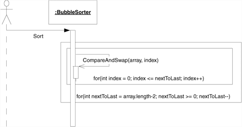
Figure 14-2 gives us a rough structure but is cumbersome and reflects none of the interesting details. Figure 14-3 is no easier to read than the code and is substantially more difficult to create. UML for these purposes leaves much to be desired.
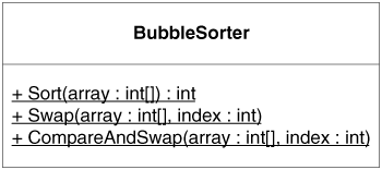
Figure 14-3. BubbleSorter sequence diagram
public class BubbleSorter
{
private static int operations;
public static int Sort(int [] array)
{
operations = 0;
if (array.Length <= 1)
return operations;
for (int nextToLast = array.Length-2;
nextToLast >= 0; nextToLast--)
for (int index = 0; index <= nextToLast; index++)
CompareAndSwap(array, index);
return operations;
}
private static void Swap(int[] array, int index)
{
int temp = array[index];
array[index] = array[index+1];
array[index+1] = temp;
}
private static void CompareAndSwap(int[] array, int index)
{
if (array[index] > array[index+1])
Swap(array, index);
operations++;
}
}
Road Maps
UML can be useful for creating road maps of large software structures. Such road maps give developers a quick way to find out which classes depend on which others and provide a reference to the structure of the whole system.

For example, in Figure 14-4, it is easy to see that Space objects have a PolyLine constructed of many Lines that are derived from LinearObject, which contains two Points. Finding this structure in code would be tedious. Finding it in a road map diagram is trivial.

Such road maps can be useful teaching tools. However, any team member ought to be able to throw such a diagram up on the whiteboard at a moment’s notice. Indeed, I drew the one in Figure 14-4 from my memory of a system I was working on ten years ago. Such diagrams capture the knowledge that all the developers must keep in their heads in order to work effectively in the system. So, for the most part, there is not much point in going to a lot of trouble to create and archive such documents. Their best use is, once again, at the whiteboard.
Back-End Documentation
The best time to create a design document that you intend to save is at the end of the project, as the last act of the team. Such a document will accurately reflect the state of the design as the team left it and could certainly be useful to an incoming team.
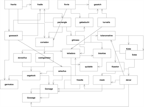
However, there are some pitfalls. UML diagrams need to be carefully considered. We don’t want a thousand pages of sequence diagrams! Rather, we want a few salient diagrams that describe the major issues in the system. No UML diagram is worse than one that is cluttered with so many lines and boxes that you get lost in the tangle, as is (Figure 14-5).
Figure 14-5. A bad but all too common example
What to Keep and What to Throw Away
Get into the habit of throwing UML diagrams away. Better yet, get into the habit of not creating them on a persistent medium. Write them on a whiteboard or on scraps of paper. Erase the whiteboard frequently, and throw the scraps of paper away. Don’t use a CASE tool or a drawing program as a rule. There is a time and place for such tools, but most of your UML should be short-lived.
Some diagrams, however, are useful to save: the ones that express a common design solution in your system. Save the diagrams that record complex protocols that are difficult to see in the code. These are the diagrams that provide road maps for areas of the system that aren’t touched very often. These are the diagrams that record designer intent in a way that is better than code can express it.
There is no point in hunting for these diagrams; you’ll know them when you see them. There’s no point in trying to create these diagrams up front. You’ll be guessing, and you’ll guess wrong. The useful diagrams will keep showing up over and over again. They’ll show up on whiteboards or scraps of paper in design session after design session. Eventually, someone will make a persistent copy of the diagram just so it doesn’t have to be drawn again. That is the time to place the diagram in some common area that everyone has access to.
It is important to keep common areas convenient and uncluttered. Putting useful diagrams on a Web server or a networked knowledge base is a good idea. However, don’t allow hundreds or thousands of diagrams to accumulate there. Be judicious about which diagrams are truly useful and which could be recreated by anybody on the team at a moment’s notice. Keep only those whose long-term survival has lots of value.
Iterative Refinement
How do we create UML diagrams? Do we draw them in one brilliant flash of insight? Do we draw the class diagrams first and then the sequence diagrams? Should we scaffold the whole structure of the system before we flesh in any of the details?
The answer to all these questions is a resounding no. Anything that humans do well, they do by taking tiny steps and then evaluating what they have done. The things that humans do not do well are things that they do in great leaps. We want to create useful UML diagrams. Therefore, we will create them in tiny steps.
Behavior First
I like to start with behavior. If I think that UML will help me think a problem through, I’ll start by drawing a simple sequence diagram or collaboration diagram of the problem. Consider, for example, the software that controls a cellular phone. How does this software make the phone call?
We might imagine that the software detects each button press and sends a message to some object that controls dialing. So we’ll draw a Button object and a Dialer object and show the Button sending many digit messages to the Dialer (Figure 14-6). (The star means many.)
Figure 14-6. A simple sequence diagram

What will the Dialer do when it receives a digit message? Well, it needs to get the digit displayed on the screen. So perhaps it’ll send displayDigit to the Screen object (Figure 14-7).
Figure 14-7. Continuation of Figure 14-6

Next, the Dialer had better cause a tone to be emitted from the speaker. So we’ll have it send the tone message to the Speaker object (Figure 14-8).
Figure 14-8. Continuation of Figure 14-7

At some point, the user will click the Send button, indicating that the call is to go through. At that point, we’ll have to tell the cellular radio to connect to the cellular network and pass along the phone number that was dialed (Figure 14-9).
Figure 14-9. Collaboration diagram
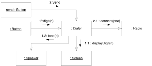
Once the connection has been established, the Radio can tell the Screen to light up the in-use indicator. This message will almost certainly be sent in a different thread of control, which is denoted by the letter in front of the sequence number. The final collaboration diagram is shown in Figure 14-10.
Figure 14-10. Cell phone collaboration diagram

Check the Structure
This little exercise has shown how we build a collaboration from nothing. Note how we invented objects along the way. We didn’t know ahead of time that these objects were going to be there; we simply knew that we needed certain things to happen, so we invented objects to do them.
But now, before continuing, we need to examine what this collaboration means to the structure of the code. So we’ll create a class diagram (Figure 14-11) that supports the collaboration. This class diagram will have a class for each object in the collaboration and an association for each link in the collaboration.
Figure 14-11. Cell phone class diagram
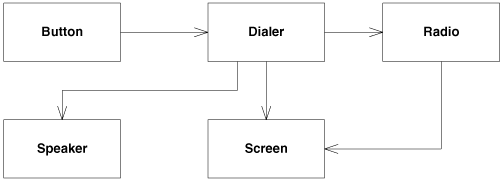
Those of you familiar with UML will note that we have ignored aggregation and composition. That’s intentional. There’ll be plenty of time to consider whether any of those relationships apply.
What’s important to me right now is an analysis of the dependencies. Why should Button depend on Dialer? If you think about this, it’s pretty hideous. Consider the implied code:
public class Button
{
private Dialer itsDialer;
public Button(Dialer dialer)
{itsDialer = dialer;}
...
}
I don’t want the source code of Button mentioning the source code of Dialer. Button is a class that I can use in many different contexts. For example, I’d like to use the Button class to control the on/off switch or the menu button or the other control buttons on the phone. If I bind the Button to the Dialer, I won’t be able to reuse the Button code for other purposes.
I can fix this by inserting an interface between Button and Dialer, as shown in Figure 14-12. Here, we see that each Button is given a token that identifies it. When it detects that the button has been pressed, the Button class it invokes the buttonPressed method of the ButtonListener interface, passing the token. This breaks the dependence of Button on Dialer and allows Button to be used virtually anywhere that needs to receive button presses.
Figure 14-12. Isolating Button from Dialer
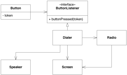
Note that this change has had no effect on the dynamic diagram in Figure 14-10. The objects are all the same; only the classes have changed.
Unfortunately, now we’ve made Dialer know something about Button. Why should Dialer expect to get its input from ButtonListener? Why should it have a method named buttonPressed within it? What has the Dialer got to do with Button?
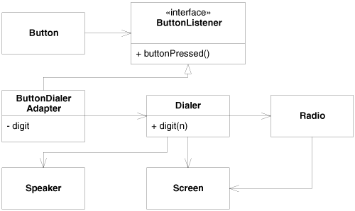
We can solve this problem, and get rid of all the token nonsense, by using a batch of little adapters (Figure 14-13). The ButtonDialerAdapter implements the ButtonListener interface, receiving the buttonPressed method and sending a digit(n) message to the Dialer. The digit passed to the Dialer is held in the adapter.
Figure 14-13. Adapting Buttons to Dialers
Envisioning the Code
We can easily envision the code for the ButtonDialerAdapter. It appears in Listing 14-2. Being able to envision the code is critically important when working with diagrams. We use the diagrams as a shortcut for code, not a replacement for it. If you are drawing diagrams and cannot envision the code that they represent, you are building castles in the air. Stop what you are doing and figure out how to translate it to code. Never let the diagrams become an end unto themselves. You must always be sure that you know what code you are representing.
Listing 14-2. ButtonDialerAdapter.cs
public class ButtonDialerAdapter : ButtonListener
{
private int digit;
private Dialer dialer;
public ButtonDialerAdapter(int digit, Dialer dialer)
{
this.digit = digit;
this.dialer = dialer;
}
public void ButtonPressed()
{
dialer.Digit(digit);
}
}
Evolution of Diagrams
Note that the last change we made in Figure 14-13 has invalidated the dynamic model back in Figure 14-10. The dynamic model knows nothing of the adapters. We’ll change that now.
Figure 14-14 shows how the diagrams evolve together in an iterative fashion. You start with a little bit of dynamics. Then you explore what those dynamics imply to the static relationships. You alter the static relationships according to the principles of good design. Then you go back and improve the dynamic diagrams.
Figure 14-14. Adding adapters to the dynamic model

Each of these steps is tiny. We don’t want to invest any more than five minutes into a dynamic diagram before exploring the static structure implied. We don’t want to spend any more than five minutes refining that static structure before we consider the impact on the dynamic behavior. Rather, we want to evolve the two diagrams together using very short cycles.
Remember, we’re probably doing this at a whiteboard, and we are probably not recording what we are doing for posterity. We aren’t trying to be very formal or very precise. Indeed, the diagrams I have included in the preceding figures are a bit more precise and formal than you would normally have to be. The goal at the whiteboard is not to get all the dots right on your sequence numbers. The goal is to get everybody standing at the board to understand the discussion. The goal is to stop working at the board and start writing code.
When and How to Draw Diagrams
Drawing UML diagrams can be a very useful activity. It can also be a horrible waste of time. A decision to use UML can be either very good or very bad. It depends on how, and how much, you choose to use it.
When to Draw Diagrams and When to Stop
Don’t make a rule that everything must be diagrammed. Such rules are worse than useless. Enormous amounts of project time and energy can be wasted in pursuit of diagrams that no one will ever read.
Draw diagrams when:
• Several people need to understand the structure of a particular part of the design because they are all going to be working on it simultaneously. Stop when everyone agrees that they understand.
• You want team consensus, but two or more people disagree on how a particular element should be designed. Put the discussion into a time box, then choose a means for deciding, such as a vote or an impartial judge. Stop at the end of the time box or when the decision can be made. Then erase the diagram.
• You want to play with a design idea, and the diagrams can help you think it through. Stop when you can finish your thinking in code. Discard the diagrams.
• You need to explain the structure of some part of the code to someone else or to yourself. Stop when the explanation would be better done by looking at code.
• It’s close to the end of the project, and your customer has requested them as part of a documentation stream for others.
Do not draw diagrams:
• Because the process tells you to.
• Because you feel guilty not drawing them or because you think that’s what good designers do. Good designers write code. They draw diagrams only when necessary.
• To create comprehensive documentation of the design phase prior to coding. Such documents are almost never worth anything and consume immense amounts of time.
• For other people to code. True software architects participate in the coding of their designs.
CASE Tools
UML CASE tools can be beneficial but also expensive dust collectors. Be very careful about making a decision to purchase and deploy a UML CASE tool.
• Don’t UML CASE tools make it easier to draw diagrams? No, they make it significantly more difficult. There is a long learning curve to get proficient, and even then the tools are more cumbersome than whiteboards, which are very easy to use. Developers are usually already familiar with them. If not, there is virtually no learning curve.
• Don’t UML CASE tools make it easier for large teams to collaborate on diagrams? In some cases. However, the vast majority of developers and development projects do not need to be producing diagrams in such quantities and complexities that they require an automated collaborative system to coordinate their diagramming activities. In any case, the best time to purchase a system to coordinate the preparation of UML diagrams is when a manual system has first been put in place, is starting to show the strain, and the only choice is to automate.
• Don’t UML CASE tools make it easier to generate code? The sum total effort involved in creating the diagrams, generating the code, and then using the generated code is not likely to be less than the cost of simply writing the code in the first place. If there is a gain, it is not an order of magnitude or even a factor of 2. Developers know how to edit text files and use IDEs. Generating code from diagrams may sound like a good idea, but I strongly urge you to measure the productivity increase before you spend a lot of money.
• What about these CASE tools that are also IDEs and show the code and diagrams together? These tools are definitely cool. However, the constant presence of UML is not important. The fact that the diagram changes as I modify the code or that the code changes as I modify the diagram does not really help me much. Frankly, I’d rather buy an IDE that has put its effort into figuring out how to help me manipulate my programs rather than my diagrams. Again, measure productivity improvement before making a huge monetary commitment.
In short, look before you leap, and look very hard. There may be a benefit to outfitting your team with an expensive CASE tool, but verify that benefit with your own experiments before buying something that could very well turn into shelfware.
But What About Documentation?
Good documentation is essential to any project. Without it, the team will get lost in a sea of code. On the other hand, too much documentation of the wrong kind is worse because you have all this distracting and misleading paper, and you still have the sea of code.
Documentation must be created, but it must be created prudently. The choice of what not to document is just as important as the choice of what to document. A complex communication protocol needs to be documented. A complex relational schema needs to be documented. A complex reusable framework needs to be documented. However, none of these things need a hundred pages of UML. Software documentation should be short and to the point. The value of a software document is inversely proportional to its size.
For a project team of 12 people working on a project of a million lines of code, I would have a total of 25 to 200 pages of persistent documentation, with my preference being for the smaller. These documents would include UML diagrams of the high-level structure of the important modules, ER (Entity-Relationship) diagrams of the relational schema, a page or two about how to build the system, testing instructions, source code control instructions, and so forth. I would put this documentation into a wiki1 or some collaborative authoring tool so that anyone on the team can access it on the screen and search it and change it as need be.
It takes a lot of work to make a document small, but that work is worth it. People will read small documents. They won’t read 1,000-page tomes.
Conclusion
A few folks at a whiteboard can use UML to help them think through a design problem. Such diagrams should be created iteratively, in very short cycles. It is best to explore dynamic scenarios first and then determine their implications on the static structure. It is important to evolve the dynamic and static diagrams together, using very short iterative cycles on the order of five minutes or less.
UML CASE tools can be beneficial in certain cases. But for the normal development team, they are likely to be more of a hindrance than a help. If you think you need a UML CASE tool, even one integrated with an IDE, run some productivity experiments first. Look before you leap.
UML is a tool, not an end in itself. As a tool, it can help you think through your designs and communicate them to others. Use it sparingly, and it will give you great benefit. Overuse it, and it will waste a lot of your time. When using UML, think small.

