19. Class Diagrams

Angela Brooks
UML class diagrams allow us to denote the static contents of—and the relationships between—classes. In a class diagram, we can show the member variables and member functions of a class. We can also show whether one class inherits from another or whether it holds a reference to another. In short, we can depict all the source code dependencies between classes.
This can be valuable. It can be much easier to evaluate the dependency structure of a system from a diagram than from source code. Diagrams make certain dependency structures visible. We can see dependency cycles and determine how best to break them. We can see when abstract classes depend on concrete classes and can determine a strategy for rerouting such dependencies.
The Basics
Classes
Figure 19-1 shows the simplest form of class diagram. The class named Dialer is represented as a simple rectangle. This diagram represents nothing more than the code shown to its right.
This is the most common way you will represent a class. The classes on most diagrams don’t need any more than their name to make clear what is going on.
A class icon can be subdivided into compartments. The top compartment is for the name of the class; the second, for the variables of the class; and the third, is for the methods of the class. Figure 19-2 shows these compartments and how they translate into code.
Figure 19-2. Class icon compartments with corresponding code
Note the character in front of the variables and functions in the class icon. A dash (–) denotes private; a hash (#), protected; and a plus (+), public.
The type of a variable, or a function argument is shown after the colon following the variable or argument name. Similarly, the return value of a function is shown after the colon following the function.
This kind of detail is sometimes useful but should not be used very often. UML diagrams are not the place to declare variables and functions. Such declarations are better done in source code. Use these adornments only when they are essential to the purpose of the diagram.
Association
Associations between classes most often represent instance variables that hold references to other objects. For example, Figure 19-3 shows an association between Phone and Button. The direction of the arrow indicates that Phone holds a reference to Button. The name near the arrowhead is the name of the instance variable. The number near the arrowhead indicates how many references are held.
In Figure 19-3, 15 Button objects are connected to the Phone object. Figure 19-4, shows what happens when there is no limit. A Phonebook is connected to many PhoneNumber objects. (The star means many) In C#, this is most commonly implemented with an ArrayList or some other collection.
Figure 19-4. One-to-many association
I could have said, “A Phonebook has many PhoneNumbers.” Instead, I avoided using the word has. This was intentional. The common OO verbs HAS-A and IS-A have led to a number of unfortunate misunderstandings. For now, don’t expect me to use the common terms. Rather, I’ll use terms that are descriptive of what happens in the software, such as is connected to.
Inheritance
You have to be very careful with your arrowheads in UML. Figure 19-5 shows why. The arrowhead pointing at Employee denotes inheritance.1 If you draw your arrowheads carelessly, it may be difficult to tell whether you mean inheritance or association. To make it clearer, I often make inheritance relationships vertical and associations horizontal.

In UML, all arrowheads point in the direction of source code dependency. Since it is the SalariedEmployee class that mentions the name of Employee, the arrowhead points at Employee. So, in UML, inheritance arrows point at the base class.
UML has a special notation for the kind of inheritance used between a C# class and a C# interface. As shown in Figure 19-6, it is a dashed inheritance arrow.2 In the diagrams to come, you’ll probably catch me forgetting to dash the arrows that point to interfaces. I suggest that you forget to dash the arrows that you draw on whiteboards, too. Life’s too short to be dashing arrows.
Figure 19-6. Realizes relationship
Figure 19-7 shows another way to convey the same information. Interfaces can be drawn as lollipops on the classes that implement them. We often see this kind of notation in COM designs.
Figure 19-7. Lollipop interface indicator
An Example Class Diagram
Figure 19-8 shows a simple class diagram of part of an ATM system. This diagram is interesting both for what it shows and for what it does not show. Note that I have taken pains to mark all the interfaces. I consider it crucial to make sure that my readers know what classes I intend to be interfaces and which I intend to be implemented. For example, the diagram immediately tells you that WithdrawalTransaction talks to a CashDispenser interface. Clearly, some class in the system will have to implement the CashDispenser, but in this diagram, we don’t care which class it is.
Figure 19-8. ATM class diagram
Note that I have not been particularly thorough in documenting the methods of the various UI interfaces. Certainly, WithdrawalUI will need more than the two methods shown there. What about PromptForAccount or InformCashDispenserEmpty? Putting those methods in the diagram would clutter it. By providing a representative batch of methods, I’ve given the reader the idea. That’s all that’s necessary.
Again note the convention of horizontal association and vertical inheritance. This helps to differentiate these vastly different kinds of relationships. Without a convention like this, it can be difficult to tease the meaning out of the tangle.
Note how I’ve separated the diagram into three distinct zones. The transactions and their actions are on the left, the various UI interfaces are all on the right, and the UI implementation is on the bottom. Note also that the connections between the groupings are minimal and regular. In one case, it is three associations, all pointing the same way. In the other case, it is three inheritance relationships, all merged into a single line. The groupings, and the way they are connected, help the reader to see the diagram in coherent pieces.
You should be able to see the code as you look at the diagram. Is Listing 19-1 close to what you expected for the implementation of UI?
public abstract class UI :
WithdrawalUI, DepositUI, TransferUI
{
private Screen itsScreen;
private MessageLog itsMessageLog;
public abstract void PromptForDepositAmount();
public abstract void PromptForWithdrawalAmount();
public abstract void InformInsufficientFunds();
public abstract void PromptForEnvelope();
public abstract void PromptForTransferAmount();
public abstract void PromptForFromAccount();
public abstract void PromptForToAccount();
public void DisplayMessage(string message)
{
itsMessageLog.LogMessage(message);
itsScreen.DisplayMessage(message);
}
}
The Details
A vast number of details and adornments can be added to UML class diagrams. Most of the time, these details and adornments should not be added. But there are times when they can be helpful.
Class Stereotypes
Class stereotypes appear between guillemet3 characters, usually above the name of the class. We have seen them before. The «interface» denotation in Figure 19-8 is a class stereotype. C# programmers can use two standard stereotypes: «interface» and «utility».
«interface»
All the methods of classes marked with this stereotype are abstract. None of the methods can be implemented. Moreover, «interface» classes can have no instance variables. The only variables they can have are static variables. This corresponds exactly to C# interfaces. See Figure 19-9.
Figure 19-9. «interface» class stereotype
I draw interfaces so often that spelling the whole stereotype out at the whiteboard can be pretty inconvenient. So I often use the shorthand in the lower part of Figure 19-9 to make the drawing easier. It’s not standard UML, but it’s much more convenient.
«utility»
All the methods and variables of a «utility» class are static. Booch used to call these class utilities.4 See Figure 19-10.
Figure 19-10. «utility» class stereotype

You can make your own stereotypes, if you like. I often use the stereotypes «persistent », «C-API», «struct», or «function». Just make sure that the people who are reading your diagrams know what your stereotype means.
Abstract Classes
In UML, there are two ways to denote that a class or a method is abstract. You can write the name in italics, or you can use the {abstract} property. Both options are shown in Figure 19-11.
Figure 19-11. Abstract classes
It’s a little difficult to write italics at a whiteboard, and the {abstract} property is wordy. So at the whiteboard, I use the convention shown in Figure 19-12 if I need to denote a class or method as abstract. Again, this isn’t standard UML but at the whiteboard is a lot more convenient.5
Figure 19-12. Unofficial denotation of abstract classes
Properties
Properties, such as {abstract} can be added to any class. They represent extra information that’s not usually part of a class. You can create your own properties at any time.
Properties are written in a comma-separated list of name/value pairs, like this:
{author=Martin, date=20020429, file=shape.cs, private}
The properties in the preceding example are not part of UML. Also, properties need not be specific to code but can contain any bit of meta data you fancy. The {abstract} property is the only defined property of UML that programmers normally find useful.
A property that does not have a value is assumed to take the Boolean value true. Thus, {abstract} and {abstract = true} are synonyms. Properties are written below and to the right of the name of the class, as shown in Figure 19-13.
Other than the {abstract} property, I don’t know when you’d find this useful. Personally, in the many years that I’ve been writing UML diagrams, I’ve never had occasion to use class properties for anything.
Aggregation
Aggregation is a special form of association that connotes a whole/part relationship. Figure 19-14 shows how it is drawn and implemented. Note that the implementation shown in Figure 19-14 is indistinguishable from association. That’s a hint.

Unfortunately, UML does not provide a strong definition for this relationship. This leads to confusion because various programmers and analysts adopt their own pet definitions for the relationship. For that reason, I don’t use the relationship at all, and I recommend that you avoid it as well. In fact, this relationship was almost dropped from UML 2.0.
The one hard rule that UML gives us regarding aggregations is simply this: A whole cannot be its own part. Therefore, instances cannot form cycles of aggregations. A single object cannot be an aggregate of itself, two objects cannot be aggregates of each other, three objects cannot form a ring of aggregation, and so on. See Figure 19-15.
Figure 19-15. Illegal cycles of aggregation between instances
I don’t find this to be a particularly useful definition. How often am I concerned about making sure that instances form a directed acyclic graph? Not very often. Therefore, I find this relationship useless in the kinds of diagrams I draw.
Composition
Composition is a special form of aggregation, as shown in Figure 19-16. Again, note that the implementation is indistinguishable from association. This time, however, the reason is that the relationship does not have a lot of use in a C# program. C++ programmers, on the other hand, find a lot of use for it.

The same rule applies to composition that applied to aggregation. There can be no cycles of instances. An owner cannot be its own ward. However, UML provides quite a bit more definition for composition.
• An instance of a ward cannot be owned simultaneously by two owners. The object diagram in Figure 19-17 is illegal. Note, however, that the corresponding class diagram is not illegal. An owner can transfer ownership of a ward to another owner.
Figure 19-17. Illegal composition
• The owner is responsible for the lifetime of the ward. If the owner is destroyed, the ward must be destroyed with it. If the owner is copied, the ward must be copied with it.
In C#, destruction happens behind the scenes by the garbage collector, so there is seldom a need to manage the lifetime of an object. Deep copies are not unheard of, but the need to show deep-copy semantics on a diagram is rare. So, though I have used composition relationships to describe some C# programs, such use is infrequent.
Figure 19-18 shows how composition is used to denote deep copy. We have a class named Address that holds many strings. Each string holds one line of the address. Clearly, when you make a copy of the Address, you want the copy to change independently of the original. Thus, we need to make a deep copy. The composition relationship between the Address and the Strings indicates that copies need to be deep.6
Figure 19-18. Deep copy implied by composition
public class Address : ICloneable
{
private ArrayList itsLines = new ArrayList();
public void SetLine(int n, string line)
{
itsLines[n] = line;
}
public object Clone()
{
Address clone = (Address) this.MemberwiseClone();
clone.itsLines = (ArrayList) itsLines.Clone();
return clone;
}
}
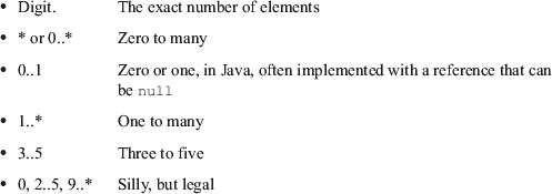
Multiplicity
Objects can hold arrays or collections of other objects, or they can hold many of the same kind of objects in separate instance variables. In UML, this can be shown by placing a multiplicity expression on the far end of the association. Multiplicity expressions can be simple numbers, ranges, or a combination of both. For example, Figure 19-19 shows a BinaryTreeNode, using a multiplicity of 2.
Figure 19-19. Simple multiplicity
Here are the allowable forms of multiplicity:
Association Stereotypes
Associations can be labeled with stereotypes that change their meaning. Figure 19-20 shows the ones that I use most often.
Figure 19-20. Association stereotypes
The «create» stereotype indicates that the target of the association is created by the source. The implication is that the source creates the target and then passes it around to other parts of the system. In the example, I’ve shown a typical factory.
The «local» stereotype is used when the source class creates an instance of the target and holds it in a local variable. The implication is that the created instance does not survive the member function that creates it. Thus, it is not held by any instance variable or passed around the system in any way.
The «parameter» stereotype shows that the source class gains access to the target instance though the parameter of one of its member functions. Again, the implication is that the source forgets all about this object once the member function returns. The target is not saved in an instance variable.
Using dashed dependency arrows, as the diagram shows, is a common and convenient idiom for denoting parameters. I usually prefer it to using the «parameter» stereotype.
The «delegate» stereotype is used when the source class forwards a member function invocation to the target. A number of design patterns apply this technique: PROXY, DECORATOR, and COMPOSITE.7 Since I use these patterns a lot, I find the notation helpful.
Nested Classes
Nested classes are represented in UML with an association adorned with a crossed circle, as shown in Figure 19-21.

Association Classes
Associations with multiplicity tell us that the source is connected to many instances of the target, but the diagram doesn’t tell us what kind of container class is used. This can be depicted by using an association class, as shown in Figure 19-22.
Figure 19-22. Association class
Association classes show how a particular association is implemented. On the diagram, they appear as a normal class connected to the association with a dashed line. As C# programmers, we interpret this to mean that the source class contains a reference to the association class, which in turn contains references to the target.
Association classes can also be classes that you write in order to hold instances of some other object. Sometimes, these classes enforce business rules. For example, in Figure 19-23, a Company class holds many Employee instances through EmployeeContracts. To be frank, I have never found this notation to be particularly useful.
Figure 19-23. Employment contract
Association Qualifiers
Association qualifiers are used when the association is implemented through some kind of key or token instead of with a normal C# reference. The example in Figure 19-24 shows a LoginTransaction associated with an Employee. The association is mediated by a member variable named empid, which contains the database key for the Employee.
Figure 19-24. Association qualifier

I find this notation useful in rare situations. Sometimes, it’s convenient to show that an object is associated to another through a database or dictionary key. It is important, however, that all the parties reading the diagram know how the qualifier is used to access the object. This is not something that’s immediately evident from the notation.
Conclusion
UML has lots of widgets, adornments, and whatchamajiggers. There are so many that you can spend a long time becoming an UML language lawyer, enabling you to do what all lawyers can: write documents nobody else can understand.
In this chapter, I have avoided most of the arcana and byzantine features of UML. Rather, I have shown you the parts of UML that I use. I hope that along with that knowledge, I have instilled within you the values of minimalism. Using too little of UML is almost always better than using too much.
Bibliography
[Booch94] Grady Booch, Object-Oriented Analysis and Design with Applications, 2d ed., Addison-Wesley, 1994.
[GOF95] Erich Gamma, Richard Helm, Ralph Johnson, and John Vlissides, Design Patterns: Elements of Reusable Object-Oriented Software, Addison-Wesley, 1995.