Chapter 4. Compiling, Linking, and Locating
I consider that the golden rule requires that if I like a program I must share it with other people who like it. Software sellers want to divide the users and conquer them, making each user agree not to share with others. I refuse to break solidarity with other users in this way. I cannot in good conscience sign a nondisclosure agreement or a software license agreement. So that I can continue to use computers without dishonor, I have decided to put together a sufficient body of free software so that I will be able to get along without any software that is not free.
In this chapter, we’ll examine the steps involved in preparing your software for execution on an embedded system. We’ll also discuss the associated development tools and see how to build the Blinking LED program shown in Chapter 3.
But before we get started, we want to make it clear that embedded systems programming is not substantially different from the programming you’ve done before. The only thing that has really changed is that you need to have an understanding of the target hardware platform. Furthermore, each target hardware platform is unique—for example, the method for communicating over a serial interface can vary from processor to processor and from platform to platform. Unfortunately, this uniqueness among hardware platforms leads to a lot of additional software complexity, and it’s also the reason you’ll need to be more aware of the software build process than ever before.
We focus on the use of open source software tools in this edition of the book. It’s wonderful that software developers have powerful operating systems and tools that are totally free and are available for exploring and altering. Open source solutions are very popular and provide tough competition for their commercial counterparts.
The Build Process
When build tools run on the same system as the program they produce, they can make a lot of assumptions about the system. This is typically not the case in embedded software development, where the build tools run on a host computer that differs from the target hardware platform. There are a lot of things that software development tools can do automatically when the target platform is well defined. [1] This automation is possible because the tools can exploit features of the hardware and operating system on which your program will execute. For example, if all of your programs will be executed on IBM-compatible PCs running Windows, your compiler can automate—and, therefore, hide from your view—certain aspects of the software build process. Embedded software development tools, on the other hand, can rarely make assumptions about the target platform. Instead, the user must provide some of her own knowledge of the system to the tools by giving them more explicit instructions.
The process of converting the source code representation of your embedded software into an executable binary image involves three distinct steps:
Each of the source files must be compiled or assembled into an object file.
All of the object files that result from the first step must be linked together to produce a single object file, called the relocatable program.
Physical memory addresses must be assigned to the relative offsets within the relocatable program in a process called relocation.
The result of the final step is a file containing an executable binary image that is ready to run on the embedded system.
The embedded software development process just described is illustrated in Figure 4-1. In this figure, the three steps are shown from top to bottom, with the tools that perform the steps shown in boxes that have rounded corners. Each of these development tools takes one or more files as input and produces a single output file. More specific information about these tools and the files they produce is provided in the sections that follow.

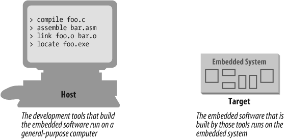
Each of the steps of the embedded software build process is a transformation performed by software running on a general-purpose computer. To distinguish this development computer (usually a PC or Unix workstation) from the target embedded system, it is referred to as the host computer. The compiler, assembler, linker, and locator run on a host computer rather than on the embedded system itself. Yet, these tools combine their efforts to produce an executable binary image that will execute properly only on the target embedded system. This split of responsibilities is shown in Figure 4-2.
In this book, we’ll be using the GNU tools (compiler, assembler, linker, and debugger) for our examples. These tools are extremely popular with embedded software developers because they are freely available (even the source code is free) and support many of the most popular embedded processors. We will use features of these specific tools as illustrations for the general concepts discussed. Once understood, these same basic concepts can be applied to any equivalent development tool. The manuals for all of the GNU software development tools can be found online at http://www.gnu.org/manual.
Compiling
The job of a compiler is mainly to translate programs written in some human-readable language into an equivalent set of opcodes for a particular processor. In that sense, an assembler is also a compiler (you might call it an “assembly language compiler”), but one that performs a much simpler one-to-one translation from one line of human-readable mnemonics to the equivalent opcode. Everything in this section applies equally to compilers and assemblers. Together these tools make up the first step of the embedded software build process.
Of course, each processor has its own unique machine language, so you need to choose a compiler that produces programs for your specific target processor. In the embedded systems case, this compiler almost always runs on the host computer. It simply doesn’t make sense to execute the compiler on the embedded system itself. A compiler such as this—that runs on one computer platform and produces code for another—is called a cross-compiler. The use of a cross-compiler is one of the defining features of embedded software development.
The GNU C compiler (gcc) and assembler (as) can be configured as either native compilers or cross-compilers. These tools support an impressive set of host-target combinations. The gcc compiler will run on all common PC and Mac operating systems. The target processor support is extensive, including AVR, Intel x86, MIPS, PowerPC, ARM, and SPARC. Additional information about gcc can be found online at http://gcc.gnu.org.
Regardless of the input language (C, C++, assembly, or any other), the output of the cross-compiler will be an object file. This is a specially formatted binary file that contains the set of instructions and data resulting from the language translation process. Although parts of this file contain executable code, the object file cannot be executed directly. In fact, the internal structure of an object file emphasizes the incompleteness of the larger program.
The contents of an object file can be thought of as a very large, flexible data structure. The structure of the file is often defined by a standard format such as the Common Object File Format (COFF) or Executable and Linkable Format (ELF). If you’ll be using more than one compiler (i.e., you’ll be writing parts of your program in different source languages), you need to make sure that each compiler is capable of producing object files in the same format; gcc supports both of the file formats previously mentioned. Although many compilers (particularly those that run on Unix platforms) support standard object file formats such as COFF and ELF, some others produce object files only in proprietary formats. If you’re using one of the compilers in the latter group, you might find that you need to get all of your other development tools from the same vendor.
Most object files begin with a header that describes the
sections that follow. Each of these sections contains one or more
blocks of code or data that originated within the source file you
created. However, the compiler has regrouped these blocks into related
sections. For example, in gcc all
of the code blocks are collected into a section called text, initialized global variables (and
their initial values) into a section called data, and uninitialized global variables
into a section called bss.
There is also usually a symbol table somewhere in the object file that contains the names and locations of all the variables and functions referenced within the source file. Parts of this table may be incomplete, however, because not all of the variables and functions are always defined in the same file. These are the symbols that refer to variables and functions defined in other source files. And it is up to the linker to resolve such unresolved references.
Linking
All of the object files resulting from the compilation in step one must be combined. The object files themselves are individually incomplete, most notably in that some of the internal variable and function references have not yet been resolved. The job of the linker is to combine these object files and, in the process, to resolve all of the unresolved symbols.
The output of the linker is a new object file that contains all
of the code and data from the input object files and is in the same
object file format. It does this by merging the text, data, and bss sections of the input files. When the
linker is finished executing, all of the machine language code from
all of the input object files will be in the text section of the new file, and all of the
initialized and uninitialized variables will reside in the new
data and bss sections, respectively.
While the linker is in the process of merging the section
contents, it is also on the lookout for unresolved symbols. For example, if one object file
contains an unresolved reference to a variable named foo, and a variable with that same name is
declared in one of the other object files, the linker will match them.
The unresolved reference will be replaced with a reference to the
actual variable. For example, if foo is located at offset 14 of the output
data section, its entry in the symbol table will now contain that
address.
The GNU linker (ld) runs on all of the same host platforms as the GNU compiler. It is a command-line tool that takes the names of all the object files, and possibly libraries, to be linked as arguments. With embedded software, a special object file that contains the compiled startup code, which is covered later in this section, must also be included within this list. The GNU linker also has a scripting language that can be used to exercise tighter control over the object file that is output.
If the same symbol is declared in more than one object file, the linker is unable to proceed. It will likely complain to the programmer (by displaying an error message) and exit.
On the other hand, if a symbol reference remains unresolved
after all of the object files have been merged, the linker will try to
resolve the reference on its own. The reference might be to a
function, such as memcpy, strlen, or malloc, that is part of the standard C
library, so the linker will open each of the libraries described to it
on the command line (in the order provided) and examine their symbol
tables. If the linker thus discovers a function or variable with that
name, the reference will be resolved by including the associated code
and data sections within the output object file. [2] Note that the GNU linker uses
selective linking, which keeps other unreferenced
functions out of the linker’s output image.
Unfortunately, the standard library routines often require some changes before they can be used in an embedded program. One problem is that the standard libraries provided with most software development tool suites arrive only in object form. You only rarely have access to the library source code to make the necessary changes yourself. Thankfully, a company called Cygnus (which is now part of Red Hat) created a freeware version of the standard C library for use in embedded systems. This package is called newlib . You need only download the source code for this library from the Web (currently located at http://sourceware.org/newlib), implement a few target-specific functions, and compile the whole lot. The library can then be linked with your embedded software to resolve any previously unresolved standard library calls.
After merging all of the code and data sections and resolving all of the symbol references, the linker produces an object file that is a special “relocatable” copy of the program. In other words, the program is complete except for one thing: no memory addresses have yet been assigned to the code and data sections within. If you weren’t working on an embedded system, you’d be finished building your software now.
But embedded programmers aren’t always finished with the build process at this point. The addresses of the symbols in the linking process are relative. Even if your embedded system includes an operating system, you’ll probably still need an absolutely located binary image. In fact, if there is an operating system, the code and data of which it consists are most likely within the relocatable program too. The entire embedded application—including the operating system—is frequently statically linked together and executed as a single binary image.
Startup code
One of the things that traditional software development tools do automatically is insert startup code: a small block of assembly language code that prepares the way for the execution of software written in a high-level language. Each high-level language has its own set of expectations about the runtime environment. For example, programs written in C use a stack. Space for the stack has to be allocated before software written in C can be properly executed. That is just one of the responsibilities assigned to startup code for C programs.
Most cross-compilers for embedded systems include an assembly language file called startup.asm, crt0.s (short for C runtime), or something similar. The location and contents of this file are usually described in the documentation supplied with the compiler.
Startup code for C programs usually consists of the following series of actions:
Disable all interrupts.
Copy any initialized data from ROM to RAM.
Zero the uninitialized data area.
Allocate space for and initialize the stack.
Initialize the processor’s stack pointer.
Call
main.
Typically, the startup code will also include a few
instructions after the call to main. These instructions will be executed
only in the event that the high-level language program exits (i.e.,
the call to main returns).
Depending on the nature of the embedded system, you might want to
use these instructions to halt the processor, reset the entire
system, or transfer control to a debugging tool.
Because the startup code is often not inserted automatically, the programmer must usually assemble it himself and include the resulting object file among the list of input files to the linker. He might even need to give the linker a special command-line option to prevent it from inserting the usual startup code. Working startup code for a variety of target processors can be found in a GNU package called libgloss .
Locating
The tool that performs the conversion from relocatable program to executable binary image is called a locator. It takes responsibility for the easiest step of the build process. In fact, you have to do most of the work in this step yourself, by providing information about the memory on the target board as input to the locator. The locator uses this information to assign physical memory addresses to each of the code and data sections within the relocatable program. It then produces an output file that contains a binary memory image that can be loaded into the target.
Whether you are writing software for a general-purpose computer or an embedded system, at some point the sections of your relocatable program must be assigned actual addresses. Sometimes software that is already in the target does this for you, as RedBoot does on the Arcom board.
In some cases, there is a separate development tool, called a locator, to assign addresses. However, in the case of the GNU tools, this feature is built into the linker (ld).
The memory information required by the GNU linker can be passed to it in the form of a linker script. Such scripts are sometimes used to control the exact order of the code and data sections within the relocatable program. But here, we want to do more than just control the order; we also want to establish the physical location of each section in memory.
What follows is an example of a linker script for the Arcom board. This linker script file is used to build the Blinking LED program covered in Chapter 3:
ENTRY (main)

MEMORY
{
    ram : ORIGIN = 0x00400000, LENGTH = 64M
    rom : ORIGIN = 0x60000000, LENGTH = 16M
}

SECTIONS
{
    data :                              /* Initialized data. */
    {
        _DataStart = . ;
        *(.data)
        _DataEnd   = . ;

    } >ram

    bss :                               /* Uninitialized data. */
    {
        _BssStart = . ;
        *(.bss)
        _BssEnd   = . ;
    } >ram

    text :                              /* The actual instructions. */
    {
        *(.text)
    } >ram
}
This script informs the GNU linker’s built-in locator about the
memory on the target board, which contains 64 MB of RAM and 16 MB of
flash ROM. [3] The linker script file instructs the GNU
linker to locate the data, bss, and text sections in RAM starting at address
0x00400000. The first executable instruction is designated with the
ENTRY command, which appears on the
first line of the preceding example. In this case, the entry point is
the function main.
Names in the linker command file that begin with an underscore (e.g.,
_DataStart) can be referenced
similarly to ordinary variables from within your source code. The
linker will use these symbols to resolve references in the input
object files. So, for example, there might be a part of the embedded
software (usually within the startup code) that copies the initial
values of the initialized variables from ROM to the data section in RAM. The start and stop
addresses for this operation can be established symbolically by
referring to the addresses as _DataStart and _DataEnd.
A linker script can also use various commands to direct the linker to perform other operations. Additional information and options for GNU linker script files can be found at http://www.gnu.org.
The output of this final step of the build process is a binary image containing physical addresses for the specific embedded system. This executable binary image can be downloaded to the embedded system or programmed into a memory chip. You’ll see how to download and execute such memory images in the next chapter.
Building the Blinking LED Program
In this section, we show an example build procedure for the Arcom VIPER-Lite development board. If another hardware platform is used, a similar process should be followed using the tools and conventions that accompany that hardware.
The installation procedure for the software development tools is provided in Appendix B. Once the tools are installed, the commands covered in the following sections are entered into a command shell. For Windows users, the command shell is a Cygwin bash shell (Cygwin is a Unix environment for Windows); for Linux users, it is a regular command shell.
Tip
In this and subsequent chapters, commands entered in a shell
environment are indicated by the number sign (#)
prompt. Commands entered in the RedBoot environment are indicated by
the RedBoot prompt (RedBoot>).
We will next take a look at the individual commands in order to manually perform the three separate tasks (compiling, linking, and locating) described earlier in this chapter. Then we will learn how to automate the build procedure with makefiles.
Compile
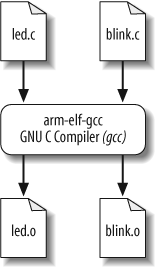
As we have implemented it, the Blinking LED example consists of two source modules: led.c and blink.c. The first step in the build process is to compile these two files. The basic structure for the gcc compiler command is:
arm-elf-gcc []options...file
The command-line options we’ll need are:
-gTo generate debugging info in default format
-cTo compile and assemble but not link
-WallTo enable most warning messages
-I../includeTo look in the directory include for header files
Here are the actual commands for compiling the C source files:
#arm-elf-gcc –g -c –Wall -I../include led.c#arm-elf-gcc -g –c -Wall -I../include blink.c
We broke up the compilation step into two separate commands, but you can compile the two files with one command. To use a single command, just put both of the source files after the options. If you wanted different options for one of the source files, you would need to compile it separately as just shown. For additional information about compiler options, take a look at http://gcc.gnu.org.
Running these commands will be a good way to verify that the tools were set up properly. The result of each of these commands is the creation of an object file that has the same prefix as the .c file, and the extension .o. So if all goes well, there will now be two additional files—led.o and blink.o—in the working directory. The compilation procedure is shown in Figure 4-3.
Link and Locate
We now have the two object files—led.o and blink.o—that we need in order to perform the second step in the build process. As we discussed earlier, the GNU linker performs the linking and locating of the object files.
For the third step, locating, there is a linker script file named viperlite.ld that we input to ld in order to establish the location of each section in the Arcom board’s memory. The basic structure for the linker and locater ld command is:
arm-elf-ld []options...file
The command-line options we’ll need for this step are:
- -Map blink.map
To generate a map file and use the given filename
- -T viperlite.ld
To read the linker script
- -N
To set the text and data sections to be readable and writable
- -o blink.exe
To set the output filename (if this option is not included, ld will use the default output filename a.out)
The actual command for linking and locating is:
# arm-elf-ld –Map blink.map –T viperlite.ld -N –o blink.exe led.o blink.oThe order of the object files determines their placement in memory. Because we are not linking in any startup code, the order of the object files is irrelevant. If startup code were included, you would want that object file to be located at the proper address. The linker script file can be used to specify where you want the startup routine (and other code) to reside in memory. Furthermore, you can also use the linker script file to specify exact addresses for code or data, should you find it necessary to do so.
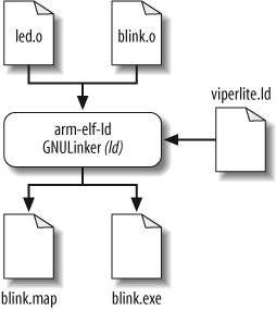
As you can see in this command, the two object files—led.o and blink.o—are the last arguments on the command line for linking. The linker script file, viperlite.ld, is also passed in for locating the data and code in the Arcom board’s memory. The result of this command is the creation of two files—blink.map and blink.exe—in the working directory. The linking and locating procedure is shown in Figure 4-4.
The .map file gives a complete listing of all code and data addresses for the final software image. If you have never seen such a map file before, be sure to take a look at this one before reading on. It provides information similar to the contents of the linker script described earlier. However, these are results rather than instructions and therefore include the actual lengths of the sections and the names and locations of the public symbols found in the relocatable program. We’ll see later how this file can be used as a debugging aid.
Format the Output File
The last step of the previous section creates an image of the Blinking LED program that we can load onto the Arcom board. In certain cases, you might need to format the image from the build procedure for your specific target platform.
One tool included with the GNU toolset that can assist with formatting images is the strip utility, which is part of the binary utilities package called binutils (pronounced “bin-you-tills”). The strip utility can remove particular sections from an object file. The basic command structure for the strip utility is:
arm-elf-strip []options... [input-file]-o output-file
The build procedure for subsequent chapters in the book generates two executable files: one with debug information and one without. The executable that contains the debug information includes dbg in its filename. The debug image should be used with gdb. If an image is downloaded with RedBoot, the nondebug image should be used.
The command used to strip symbol information is:
# arm-elf-strip --remove-section=.comment blinkdbg.exe -o blink.exeThis removes the section named .comment from the image blinkdbg.exe and creates the new output
file blink.exe.
There might be another time when you need an image file that can be burned into ROM or flash. The GNU toolset has just what you need for this task. The utility objcopy (object copy) is able to copy the contents of one object file into another object file. The basic structure for the objcopy utility is:
arm-elf-objcopy []options[input-file]output-file
For example, let’s suppose we want to convert our Blinking LED program from ELF format into an Intel Hex Format file. [4] The command line we use for this is:
# arm-elf-objcopy -O ihex blink.exe blink.hexThis command uses the –O ihex option to generate an Intel Hex Format file. The input file is blink.exe (the objcopy utility determines the input file type). Finally, the output file is named blink.hex.
Warning
If no output filename is given, the strip and objcopy utilities overwrite the original input file with the generated file.
Some of the other GNU tools are useful for providing other information about the image you have built. For example, the size utility, which is part of the binutils package, lists the section sizes and total size for a given object file. Here is the command for using the size utility:
# arm-elf-size blink.exeThe resulting output is:
text    data     bss     dec     hex filename
 328       0       0     328     148 blink.exe
The top row consists of column headings and shows the sections
text, data, and bss. The Blinking LED program contains 328
bytes in the text section, no bytes
in the data section, and no bytes
in the bss section. The dec column shows the total image size in
decimal, and the hex column shows
it in hexadecimal (decimal 328 = hexadecimal 0x148). These total sizes
are in bytes. The last column, filename, contains the filename of the
object file.
You will notice that the size of the section, 328 bytes, is much smaller than the approximately 3 KB file size of our blink.exe. This is because debugging information is located also in the blink.exe file.
Additional information about the other GNU binutils can be found online at http://www.gnu.org.
We’re now ready to download the program to our development board, which we’ll do in the next chapter. To wrap up our discussion of building programs, let’s take a quick look at another useful tool in the build process.
A Quick Look at Makefiles
You can imagine how tedious the build process could be if you had a large number of source code files for a particular project. Manually entering individual compiler and linker commands on the command line becomes tiresome very quickly. In order to avoid this, a makefile can be used. A makefile is a script that tells the make utility how to build a particular program. (The make utility is typically installed with the other GNU tools.) The make utility follows the rules in the makefile in order to automatically generate output files from a set of input source files.
Makefiles might be a bit of a pain to set up, but they can be a great timesaver and a very powerful tool when building project files over and over (and over) again. Having a sample available can reduce the pain of setting up a makefile.
The basic layout for a makefile build rule is:
target:   prerequisite
          command
The target is what is going to
be built, the prerequisite is a file
that must exist before the target can
be created, and the command is a
shell command used to create the target. There can be multiple prerequisites on the target line (separated by
white space) and/or multiple command lines. But be sure to put a tab,
not spaces, at the beginning of every line containing a command.
Here’s a makefile for building our Blinking LED program:
XCC     = arm-elf-gcc
LD      = arm-elf-ld
CFLAGS  = -g -c -Wall \
          -I../include
LDFLAGS = -Map blink.map -T viperlite.ld -N

all: blink.exe

led.o: led.c led.h
    $(XCC) $(CFLAGS) led.c

blink.o: blink.c led.h
    $(XCC) $(CFLAGS) blink.c

blink.exe: blink.o led.o viperlite.ld
    $(LD) $(LDFLAGS) -o $@ led.o blink.o

clean:
    -rm -f blink.exe *.o blink.map
The first four statements in this makefile contain variables for use in the makefile. The variable names are on the left side of the equal sign. In this makefile, the respective variables do the following:
XCCDefines the compiler executable program
LDDefines the linker executable program
CFLAGSDefines the flags for the compiler
LDFLAGSDefines the flags for the linker
Variables in a makefile are used to eliminate some of the
duplication of text as well as to ease portability. In order to use a
variable in the code, the syntax $() is used with the variable name enclosed in
the parentheses.
Note that if a line in a makefile gets too long, you can continue
it on the following line by using the backslash (\), as
shown with the CFLAGS
variable.
Now for the build rules. The build targets in this file are
all, led.o, blink.o, and blink.exe. Unless you specify a target when
invoking the make utility, it searches for the first target
(in this case, the first target is all) and tries to build it; this, in turn, can
lead to it finding and building other targets. The make utility creates (or re-creates, as the
case may be) the target file if it does not exist or if the prerequisite
files are more recent than the target file.
At this point, it might help to look at the makefile from the
bottom up. In order for blink.exe to
be created, blink.o and led.o need to be built as shown in the
prerequisites. However, since these files don’t exist, the make utility will need to create them first.
It will search for ways to create these two files and will find them
listed as targets in the makefile. The make utility can create these files because
the prerequisites (the source files) for these two targets exist.
Because the targets led.o and
blink.o are handled similarly, let’s
focus on just one of them. The prerequisites for the target led.o are led.c and led.h. As stated above, the command tells the
make utility how to create the
target. The first part of the command for led.o is a reference to the variable XCC, as indicated by the syntax $(XCC), and the next part of the command is a
reference to the variable CFLAGS, as
indicated by the syntax $(CFLAGS).
The make utility simply replaces
variable references with the text assigned to them in the makefile. The
final part of the command is the source file led.c. Strung together, these elements
construct the command that the make
utility executes. This generates a command on the shell command line as
follows:
arm-elf-gcc -g -c -Wall -I../include led.c
This is the same command we entered by hand in order to compile the led.c file earlier in this chapter, in the section “Building the Blinking LED Program.” The make utility compiles blink.c in the same way.
At this point, the make
utility has all of the prerequisites needed to generate the target
blink.exe default target. The command
that the make utility executes (the
same command we entered by hand to link and locate the Blinking LED
program) to build blink.exe
is:
arm-elf-ld -Map blink.map -T viperlite.ld -N -o blink.exe led.o blink.o
You may notice that in this makefile the linker is invoked directly. Instead, gcc could have been used to invoke the linker indirectly with the following line:
arm-elf-gcc -Wl,-Map,blink.map -T viperlite.ld -N -o blink.exe led.o blink.o
When invoking the linker indirectly, the special option –Wl is used so that gcc passes the request to generate a linker map file to the linker rather than trying to parse the argument itself. While this simple Blinking LED program does not need to link using gcc, you should remember that more complex C programs may need special runtime library support from gcc and will need to be linked in this way.
The last part of the makefile is the target clean. However, because it was not needed for
the default target, the command was not executed.
To execute the makefile’s build instructions, simply change to the directory that contains the makefile and enter the command:
# makeThe make utility will search the current directory for a file named makefile. If your makefile has a different name, you can specify that on the command line following the -f option.
With the previous command, the
make utility will make the first target it
finds. You can also specify targets on the command line for the
make utility. For example, because
all is the default target in the
preceding makefile, you can just as easily use the following
command:
# make allA target called clean is
typically included in a makefile, with commands for removing old object
files and executables, in order to allow you to create a fresh build.
The command line for executing the clean target is:
# make cleanKeep in mind that we’ve presented a very basic example of the make utility and makefiles for a very basic project. The make utility contains very powerful tools within its advanced features that can benefit you when executing large and more complex projects.
Tip
It is important to keep the makefile updated as your project changes. Remember to incorporate new source files and keep your prerequisites up to date. If prerequisites are not set up properly, you might change a particular source file, but that source file will not get incorporated into the build. This situation can leave you scratching your head.
Additional information about the GNU make utility can be found online at http://www.gnu.org as well as in the book Managing Projects with GNU make, by Robert Mecklenburg (O’Reilly). These resources will give you a deeper understanding of both the make utility and makefiles and allow you to use their more powerful features.
[1] Used this way, the term “target platform” is best understood to include not only the hardware but also the operating system that forms the basic runtime environment for your software. If no operating system is present, as is sometimes the case in an embedded system, the target platform is simply the processor on which your program runs.
[2] We are talking only about static linking here. When dynamic linking of libraries is used, the code and data associated with the library routine are not inserted into the program directly.
[1] Additional information about RedBoot can be found online at http://ecos.sourceware.org/redboot. The RedBoot User’s Guide is located on this site as well. A description of the RedBoot startup procedure is contained in the book Embedded Software Development with eCos, by Anthony Massa (Prentice Hall PTR).
[3] There is also a version of the Arcom board that contains 32 MB of flash. If you have this version of the board, change the linker script file as follows:
rom : ORIGIN = 0x60000000, LENGTH =
            32M
[4] Intel Hex format is an ASCII file format devised by Intel for storing and downloading binary images.