

Operations
This chapter discusses considerations when planning for the operational management of the Coordinated Timing Network (CTN) once your configuration is in a Mixed or STP-only CTN. This chapter covers the following topics:
|
Note: Configuring the Coordinated Timing Network is covered in the Server Time Protocol Implementation Guide, SG24-7281.
|
3.1 Displaying and monitoring the environment
This section discusses the facilities available for monitoring your Mixed and STP-only CTNs. The facilities covered are:
•CPC Details panel
•System (Sysplex) Time panel
•z/OS commands and messages
•CFCC commands and messages
3.1.1 CPC Detail panel
The CPC Details panel on the Hardware Management Console (HMC) or Support Element (SE) is the first panel to look at for timing information about a server, as shown in Figure 3-1. If your server has the STP Feature Code #1021 installed, there will be a tab entitled STP Information. This is the easiest way to check whether your servers have the STP feature code installed. The number of fields shown on the STP Information tab varies depending on the type of timing network. This is a display-only panel. It does not allow for any modification of the timing network. Any changes to the CTN require you to cancel out of the panel and return (there is no refresh button).
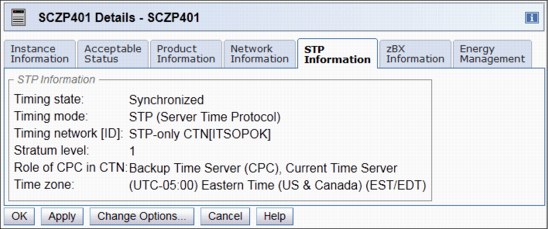
Figure 3-1 CPC Details panel from HMC Workplace
The left Context-Sensitive Help area is a newly added function for HMC and SE Version 2.10.0 that provides brief descriptions of the action buttons available on each individual panel. The buttons can be sequentially highlighted by pressing the Tab key and thus getting the information for all of them. The help function itself is activated or deactivated by clicking the i button in the upper right corner of the opened windows (Figure 3-1).
|
Note: Ensure that the HMC that you intend to use as an operational focal point for CTN management is at the latest driver level with the latest maintenance change levels (MCLs).
|
3.1.2 System (Sysplex) Time panel
When the System (Sysplex) Time icon is selected on the HMC, with a single CPC targeted, initially you will see the Secondary Object Notification for Disruptive Task message, as shown in Figure 3-2. This message reminds the user that time configuration commands can potentially be disruptive to operating system images on this CPC. If your server is not equipped with the ETR feature or the STP feature #1021, then this task is not available.
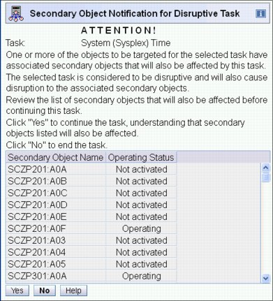
Figure 3-2 Secondary Object Notification for Disruptive Task
|
Note: This notification window serves as a reminder that changes made in this task can potentially be disruptive to the secondary object names listed.
However. if no changes are made in the Sysplex Timer related tasks (view only) there is no risk of disruption.
|
After selecting Yes, you will see the panel displayed in Figure 3-3.
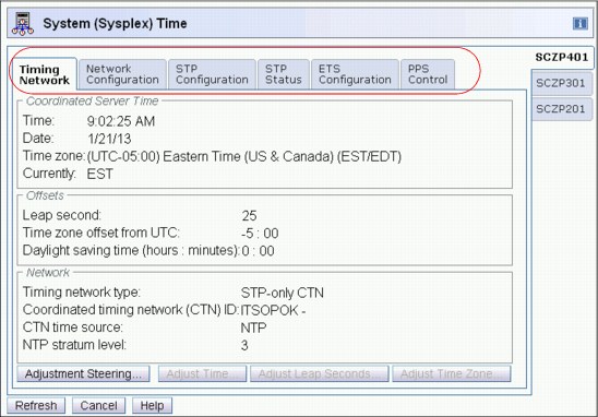
Figure 3-3 System (Sysplex) Time panel for single-selected CPC: Timing Network tab
The number of tabs on the panel (Figure 3-3) varies depending on the type of server and what features are installed on it, as shown in Table 3-1. If your environment consists of different server types, ensure that your operations staff recognizes the differences when displaying these panels.
Table 3-1 The tabs displayed on the server
|
Server
|
Timing
network
|
Network
config
|
ETR
config
|
ETR
status
|
STP
config
|
STP
status
|
ETS
config
|
PPS
control
|
|
zEC12 (STP only)
|
|
|
|
|
|
|
|
|
|
z196 and z114 (STP only)
|
|
|
|
|
|
|
|
|
|
z9/z101 with ETR and STP features
|
|
|
|
|
|
|
|
|
|
z990/z890 with ETR and STP features
|
|
|
|
|
|
|
|
|
|
z9 with STP feature only
|
|
|
|
|
|
|
|
|
|
z990/890 with STP feature only
|
|
|
|
|
|
|
|
|
|
All Servers with ETR feature only
|
|
|
|
|
|
|
|
|
1 z10 includes the ETR feature by default.
Timing network type operations summary
Table 3-2 summarizes what operation is performed from each tab in the various configurations. For details about how to perform a particular operation on a tab, refer to Part 2 of the Server Time Protocol Implementation Guide, SG24-7281.
Table 3-2 STP tabbed display operations summary
|
Type
|
Timing
network
|
Network
configuration
|
ETR
configuration
|
ETR
status
|
STP
configuration
|
STP
status
|
ETS
configuration
|
|
ETR
|
Display only
|
N/A
|
Manage ports and ETR ID
|
Display only
|
Join a Mixed CTN
|
Display only
|
N/A
|
|
Mixed CTN
|
Display only
|
N/A
|
Manage ports and ETR ID
|
Display only
|
Join a Mixed CTN, change to STP, or change to ETR1
|
Display only
|
N/A
|
|
STP-only CTN
|
Time/offset adjustments (enabled on CTS only)2
|
Role
assignment3 (enabled on CTS only)
|
N/A
|
Display only4
|
Join an STP CTN or change to Mixed CTN5
|
Display only
|
Define ETS (PTS and BTS)
|
1 Changing to a different Mixed CTN is disruptive for z/OS.
2 This includes Adjustment Steering (display only), Adjust Time and Adjust Time zone, and Leap second offsets.
3 This is a global change to the CTN.
4 N/A for zEnterprise Servers.
5 Changing to a different STP-only CTN is disruptive for z/OS.
In the following sections we provide a brief description of the seven tabs. The most relevant tabs in this planning phase are the Timing Network, ETR Status, and STP Status. The seven tabs are covered in detail in the migration chapters in Server Time Protocol Implementation Guide, SG24-7281.
Timing Network tab
The information shown on the Timing Network tab (Figure 3-3 on page 80) displays overall timing information for the CTN, including the current date and time, local time offsets, and general timing network information. The information displayed here is identical on each server in the CTN.
The Coordinated Server Time represents the date and time for the CTN. The Offsets section displays the leap second offset and other offset information that it varies depending on whether it is an ETR network, Mixed or STP-only CTN, and whether a time zone offset has been defined.
The Network section displays general information about the CTN, including timing network type, CTN ID, and CTN time source. If the CTN time source is an NTP server, as shown in Figure 3-3 on page 80, its NTP stratum level and source ID also will be displayed.
Network Configuration tab
The information shown on the Network Configuration tab depends on the network type configured. By looking on the Network Configuration tab for an existing configuration, you can tell whether you are in an ETR network, Mixed CTN, or STP-only CTN. Figure 3-4 shows the Network Configuration tab for the SCSZP201 server, which is not part of any timing network.1
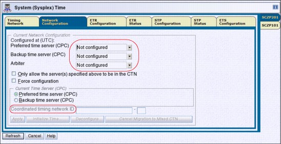
Figure 3-4 Network Configuration tab: No timing network configured
ETR Configuration tab
This tab allows users to view and modify the ETR network ID and ETR ports status (Figure 3-5). Information and data on this panel is not applicable to STP-only CTN.
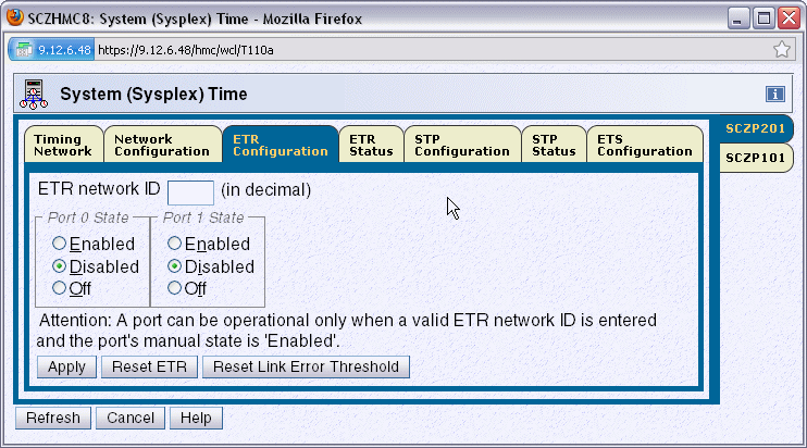
Figure 3-5 ETR Configuration tab
ETR Status tab
The ETR Status tab is used to display the configuration and operational state of the connections to the Sysplex Timer. The ETR Status tab displays information about the connected Sysplex Timer units and the server’s TOD clock. Figure 3-6 shows an example of the ETR Status tab for a server in STP timing mode.
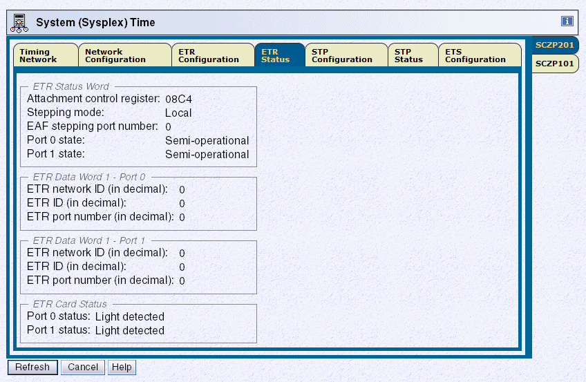
Figure 3-6 System (Sysplex) Time panel for multiple-selected CPCs: ETR Status tab
|
Note: If the ETR feature is actively connected to an NTP server through the PPS port, status information is not applicable.
|
For each ETR port connected to a Sysplex Timer, the following information received from the attached unit is displayed:
ETR network ID Network ID of the Sysplex Timer to which the ETR port is connected
ETR ID Identifies the Sysplex Timer that sends the ETR data
ETR port number Port number of the Sysplex Timer output port that sends the ETR data
If the configuration has been properly set, both ports display the same ETR network ID as the value entered in the ETR Configuration tab.
|
Important: If the values displayed are not identical, the state indicates semi-operational.
|
The ETR network ID, ETR ID, and ETR port number data is for information only. The values are obtained from the Sysplex Timer unit and can only be modified from the Sysplex Timer Console application.
If you are planning for a migration from ETR to Mixed-CTN or Mixed-CTN to STP-only, use this panel to map out the connectivity between your server and the Sysplex Timers.
STP Configuration tab
The STP Configuration tab allows you to enter and modify the timing network name, depending on the changes that you want to make (Figure 3-7).2
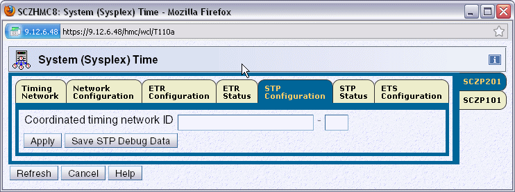
Figure 3-7 STP configuration tab
STP Status tab
The STP Status tab on the System (Sysplex) Time panel displays STP information from the point of view of the selected server. This tab can be used to identify the topology of the CTN from the perspective of the selected server. Figure 3-8 shows an example of the STP Status tab for a server in STP timing mode.
The timing state is of particular importance. It can be unsynchronized, synchronized, or stopped. If this value is anything other than synchronized then this server is not actively participating in the CTN.
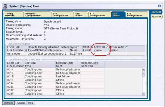
Figure 3-8 STP Status tab
The System Information section identifies the remote servers (CPCs) that are directly attached to this server for STP purposes. As soon as the STP portion of the CTN ID is applied to this server, coupling links that are initialized to transport STP messages for this CTN ID are listed using the PCHID addresses and are grouped according to the system that is directly attached to the links. Additionally, the stratum level, active STP version, and maximum STP version for each directly attached system are shown. The information provided in this section can be used to build a topology diagram of the CTN.
Servers with different maximum STP versions can coexist in the same CTN. When two attached servers are operating different STP versions, communication between the two servers uses the lowest version number installed. The version number used is indicated in the active STP version column.
|
Tip: In conjunction with the Timing Network tab, a CTN topology diagram can be built using the information from the stratum level of the current server and the stratum level of each of the directly attached servers.
|
The Local Uninitialized STP Links table identifies all coupling links defined in the active IOCDS that can be used by this server. Each entry in this table represents a link that is currently in an uninitialized state. The Reason Codes sent and received provide further information to assist in determining why the link is not initialized for STP.
ETS Configuration tab
On the ETS Configuration tab you can configure your ETS for an STP-only CTN, for both PTS and BTS servers.
Although by default only CTS/PTS adjusts CST to the ETS, we recommend that the BTS also be ETS configured. If an ETS is configured, the ETS device is monitored and errors are logged. If an ETS is configured as NTP or NTP with pulse per second (PPS), it provides redundancy of the ETS for the STP-only CTN.
PPS Control tab
On zEnterprise servers, through the PPS Control tab, you can test and control the use of the PPS signal (if PPS port is connected to an NTP server with an active PPS port), as shown in Figure 3-9.
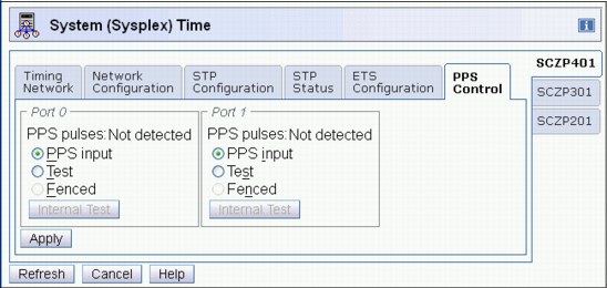
Figure 3-9 PPS Control tab (zEnterprise servers only)
3.1.3 z/OS display commands
There are a number of z/OS commands that display information about the timing mode or the status of the CTN as viewed by z/OS itself. The output from these commands can change depending on the CTN type and the timing mode that the server is currently using.
DISPLAY ETR
Prior to STP, the DISPLAY ETR command was used to display the synchronization mode and the status of the ETR ports as seen by z/OS. With STP support, the command itself has not changed. However, the output has been updated to display STP-related information where applicable.
In an ETR network
When the server is in an ETR network, it is in ETR timing mode synchronized to a Sysplex Timer. Because no CTN ID has been defined, all of the information is ETR-related. See Example 3-1.
Example 3-1 z/OS DISPLAY ETR in an ETR network
-D ETR
IEA282I 09.11.21 TIMING STATUS 010
SYNCHRONIZATION MODE = ETR
CPC PORT 0 <== ACTIVE CPC PORT 1
OPERATIONAL OPERATIONAL
ENABLED ENABLED
ETR NET ID=31 ETR NET ID=31
ETR PORT=21 ETR PORT=21
ETR ID=13 ETR ID=12
In a Mixed CTN on a server in ETR timing mode
If a server in a Mixed CTN is synchronized to the Sysplex Timer, it is in ETR timing mode and is a stratum 1 in the Mixed CTN. In this case, both Sysplex Timer-related information and CTN ID information are displayed. The format is similar to that in Example 3-1. However, an extra line is added to display the CTN ID, as shown in Example 3-2.
Example 3-2 z/OS DISPLAY ETR in a Mixed CTN with ETR timing mode
D ETR
IEA282I 14.48.26 TIMING STATUS 951
SYNCHRONIZATION MODE = ETR
CPC PORT 0 <== ACTIVE CPC PORT 1
OPERATIONAL OPERATIONAL
ENABLED ENABLED
ETR NET ID=31 ETR NET ID=31
ETR PORT=01 ETR PORT=01
ETR ID=01 ETR ID=00
THIS SERVER IS PART OF TIMING NETWORK ITSOPOK -31
In a Mixed CTN on a server in STP timing mode
It is also possible to have servers in a Mixed CTN that are synchronized using STP messages with no active connection to a Sysplex Timer. They are stratum 2 or stratum 3 servers in STP timing mode.
Example 3-3 shows that the server is in a Mixed CTN, because the CTN ID contains both STP ID and ETR network ID components.
Example 3-3 z/OS DISPLAY ETR in a Mixed CTN with STP timing mode
-D ETR
IEA386I 14.40.19 TIMING STATUS 337
SYNCHRONIZATION MODE = STP
THIS SERVER IS A STRATUM 2
CTN ID = ITSOPOK -31
NUMBER OF USABLE TIMING LINKS = 4
STP-only CTN, all servers in STP timing mode
In an STP-only CTN the TOD clock is being steered to the time provided by the Current Time Server (CTS). No reference to a Sysplex Timer is displayed. See Example 3-4.
Example 3-4 z/OS DISPLAY ETR in an STP-only CTN
-D ETR
IEA386I 11.25.04 TIMING STATUS 787
SYNCHRONIZATION MODE = STP
THIS SERVER IS A STRATUM 3
CTN ID = ITSOPOK
THE STRATUM 1 NODE ID = 002097.S18.IBM.02.000000099999
NUMBER OF USABLE TIMING LINKS = 4
THIS STP TIMING NETWORK HAS NO SERVER TO ACT AS ARBITER
The DISPLAY ETR output in an STP-only CTN incorporates additional information in comparison to STP mode within a Mixed CTN. Node ID information for the CTS is displayed, in addition to a number of extra optional lines that show a different output depending on the CTN topology and whether this server has been assigned a Preferred Time Server, Backup Time Server, or Arbiter Server role. More DISPLAY ETR commands are illustrated in the following section.
DISPLAY ETR examples
Determining the Current Time Server can be done by using the DISPLAY ETR command and checking which server is performing the stratum 1 role, as shown in Example 3-5.
Example 3-5 z/OS DISPLAY ETR command: identifying CTS (stratum 1)
D ETR
IEA386I 14.50.16 TIMING STATUS 931
SYNCHRONIZATION MODE = STP
THIS SERVER IS A STRATUM 2
CTN ID = ITSOPOK
THE STRATUM 1 NODE ID = 002097.E26.IBM.02.000000088888
THIS IS THE BACKUP TIME SERVER
Example 3-6 shows checking CTN roles using the z/OS DISPLAY ETR command. Observe that there is currently no Backup Time Server configured and, implicitly, there is no Arbiter.
Example 3-6 z/OS command DISPLAY ETR: no BTS configured
D ETR
IEA386I 15.12.27 TIMING STATUS 975
SYNCHRONIZATION MODE = STP
THIS SERVER IS A STRATUM 1
CTN ID = hmctest
THE STRATUM 1 NODE ID = 002097.E26.IBM.02.00000001DE50
THIS IS THE PREFERRED TIME SERVER
THIS STP NETWORK HAS NO BACKUP TIME SERVER
THIS STP NETWORK HAS NO SERVER TO ACT AS ARBITER
Once a Backup Time Server has been configured, the absence of the line pertaining to the Backup Time Server indicates that the CTN now has a BTS configured. However, the CTN has no Arbiter defined, as shown in Example 3-7.
Example 3-7 z/OS command DISPLAY ETR: CTN has PTS and BTS, no Arbiter
D ETR
IEA386I 15.15.43 TIMING STATUS 982
SYNCHRONIZATION MODE = STP
THIS SERVER IS A STRATUM 1
CTN ID = hmctest
THE STRATUM 1 NODE ID = 002097.E26.IBM.02.00000001DE50
THIS IS THE PREFERRED TIME SERVER
THIS STP NETWORK HAS NO SERVER TO ACT AS ARBITER
As with the Backup Time Server, issue the z/OS DISPLAY ETR command to determine whether the STP-only CTN has an Arbiter defined. Absence of the line pertaining to the Arbiter indicates that the Arbiter has been configured, as shown in Example 3-8.
Example 3-8 z/OS command DISPLAY ETR: both BTS and Arbiter configured
D ETR
IEA386I 15.18.08 TIMING STATUS 993
SYNCHRONIZATION MODE = STP
THIS SERVER IS A STRATUM 1
CTN ID = hmctest
THE STRATUM 1 NODE ID = 002097.E26.IBM.02.00000001DE50
THIS IS THE PREFERRED TIME SERVER
The number of usable timing links account for the number of STP-initialized links that supply or can supply timing information to this server. That is why this line does not appear in the D ETR output of a server in ETR timing mode or a Current Time Server because it is the source of timing information. A stratum 2 server includes links to another stratum 2 server since if it transitions to a stratum 3 server those links become sources of timing signals.
SETETR PORT=n
The SETETR command can only be used to enable Sysplex Timer ports that have been previously disabled by z/OS as a consequence of hardware error. A Sysplex Timer port disabled by a hardware problem can be enabled after the problem has been corrected.
The syntax for the SETETR command is SETETR PORT=n, where n specifies the number of the ETR port to be enabled (Example 3-9).
Example 3-9 SETETR command
-D ETR
IEA282I 09.34.52 TIMING STATUS 031
SYNCHRONIZATION MODE = ETR
CPC PORT 0 <== ACTIVE CPC PORT 1
OPERATIONAL OPERATIONAL
ENABLED DISABLED
ETR NET ID=31 ETR NET ID=31
ETR PORT=21 ETR PORT=21
ETR ID=13 ETR ID=12
THIS SYSTEM IS PART OF TIMING NETWORK ITSOPOK -31
-SETETR PORT=1
IEA283I ETR PORT 1 IS ENABLED
Example 3-10 z/OS SETETR in STP timing mode
IEA384I SETETR COMMAND IS NOT VALID IN STP TIMING MODE
DISPLAY XCF,SYSPLEX,ALL
The DISPLAY XCF,SYSPLEX,ALL command displays the system status and the last recorded system status monitor time stamp for each system in the sysplex (Example 3-11).
Example 3-11 z/OS DISPLAY XCF,SYSPLEX,ALL in a Mixed CTN
D XCF,S,ALL
IXC335I 17.31.31 DISPLAY XCF 375
SYSTEM TYPE SERIAL LPAR STATUS TIME SYSTEM STATUS
SC80 2097 8888 01 11/22/2007 17:31:28 ACTIVE TM=STP
SC74 2094 9999 01 11/22/2007 17:31:29 ACTIVE TM=STP
SC75 2084 7777 15 11/22/2007 17:31:30 ACTIVE TM=ETR
The output from this command incorporates information about the timing mode in effect.
DISPLAY CF
The DISPLAY CF command does not directly provide information regarding the CTN type or timing mode of the server. However, the output does display the CF Request Time Ordering status. If the CTN is a Mixed or STP-only CTN in a Parallel Sysplex configuration, the requirement is that all servers support CF Request Time Ordering.
|
Note: CF Request Time Ordering is also referred to as the Message Time Ordering Facility (MTOF).
|
The DISPLAY CF command can be used to verify whether CF Request Time Ordering is required and enabled, as shown in Example 3-12.
Example 3-12 z/OS DISPLAY CF
D CF
IXL150I 14.55.46 DISPLAY CF 975
COUPLING FACILITY 002094.IBM.02.000000088888
PARTITION: 2C CPCID: 00
CONTROL UNIT ID: FFFC
NAMED CF7B
COUPLING FACILITY SPACE UTILIZATION
. . . . . . .
CFCC RELEASE 15.00, SERVICE LEVEL 02.09
BUILT ON 04/30/2009 AT 14:18:00
COUPLING FACILITY HAS 1 SHARED AND 0 DEDICATED PROCESSORS
DYNAMIC CF DISPATCHING: ON
CF REQUEST TIME ORDERING: REQUIRED AND ENABLED
. . . . .
STP requires that each coupling facility within a Parallel Sysplex is enabled for CF Request Time Ordering before any server within the Parallel Sysplex can be defined in a Mixed or STP-only CTN.
Example 3-13 displays the other CF Request Time Ordering messages that can appear in the output of the DISPLAY CF.
Example 3-13 CF Request Time Ordering messages
CF REQUEST TIME ORDERING: NOT-REQUIRED AND ENABLED
CF REQUEST TIME ORDERING: NOT-REQUIRED AND NOT-ENABLED
CF REQUEST TIME ORDERING: REQUIRED AND NOT-ENABLED
REASON: FUNCTION NOT INSTALLED ON THIS SYSTEM
REASON: ETR NOT CONNECTED TO COUPLING FACILITY
REASON: REQUEST TIME ORDERING FUNCTION FAILURE
REASON: ETR NETID MISMATCH - CF ETR NETID: etr netid
REASON: CTNID MISMATCH - CF CTNID: ctnid
There are two time-related CFCC commands, which are described in “Coupling facility commands” on page 117.
3.1.4 z/OS messages
Ensure that your operations staff reviews all STP-related messages and plan for which ones they would like automation (or console operator staff) to take action on. Note that some messages will be issued on every member of the sysplex with STPMODE YES specified, which might cause automation to take multiple or redundant actions.
Refer to Appendix B, “Server Time Protocol (STP) messages in z/OS” on page 197, for all STP-related messages.
New z/OS messages in April 2009 STP enhancements
Prior to z/OS 1.11, messages related to the following STP events were only posted as hardware messages on the HMC:
•ETS failure or status change events
•CTS role changing from PTS to BTS or vice versa because of STP recovery
To improve the delivery of important information to the operator and to better integrate with system automation tools, z/OS 1.11 (also rolled back to 1.9 and 1.10 with PTFs) adds new STP-related messages in addition to the hardware messages posted on the HMC.
|
Note: These messages will be posted by every z/OS sysplex member using STPMODE YES in the CTN. The operations staff or automation tools can monitor these messages even if there are stand-alone CFs in the CTN assigned the special roles of PTS and BTS.
|
To address the CTS change a new z/OS message was created:
IEA395I THE CURRENT TIME SERVER HAS CHANGED TO THE cccccc
Where cccccc is BACKUP or PREFERRED. This informational message does not require any action, but ensures that the operational staff responsible for STP is aware of the change.
When an ETS was configured with the Sysplex Timers it provided a means to notify operations of ETS-related alerts, for example:
IEA272I ETR SERVICE IS REQUESTED. REASON CODE=045
Where 45 is The external time source is not responding”.
The following new message is created for all ETS-related alerts if an ETS is configured with STP:
IEA031I STP ALERT RECEIVED. STP ALERT CODE=cc
Refer to Appendix B, “Server Time Protocol (STP) messages in z/OS” on page 197, for a list of STP-related z/OS messages.
z/OS messages context
z/OS messages might help you identify various configuration issues and status changes for the servers in your CTN. However, consider planning your servers roles and changing your CTN configuration considering the following aspects:
•Although stand-alone CFs will typically provide best connectivity to other servers requiring time synchronization, stand-alone CFs do not produce z/OS messages for operations or interception by automation routines. For example, the following information messages at IPL or interrupt time might not be displayed:
IEA380I THIS SYSTEM IS NOW OPERATING IN STP TIMING MODE.
IEA381I THE STP FACILITY IS NOT USABLE. SYSTEM CONTINUES IN LOCAL TIMING MODE
•If the condition being raised relates to connectivity between two servers, the information might be available to a z/OS system image at the other end of the link. However, if both ends of the link are CF partitions, no warning message is available to the user.
•There are several IEAxxx and IXCxxx messages that report current and changed timing status. As an example, the following message reports the result of a successful migration from a mixed CTN to an STP-only CTN:
IXC438I COORDINATED TIMING INFORMATION HAS BEEN UPDATED
FOR SYSTEM: scpz101
PREVIOUS CTNID: ITSOPOK-31
CURRENT CTNID: ITSOPOK
•In general, there are no z/OS messages that are posted only on the PTS, BTS, or Arbiter.
– Certain messages do not appear on the CTS since it is the time source:
IEA382I THIS SERVER HAS ONLY A SINGLE LINK AVAILABLE FOR TIMING PURPOSES.
IEA383I THIS SERVER RECEIVES TIMING SIGNALS FROM ONLY ONE OTHER NETWORK NODE.
IEA281I STP SYNC CHECK THRESHOLD EXCEEDED. CPC CONTINUES IN LOCAL MODE.
IEA390I TOD CLOCKS DYNAMICALLY ADJUSTED TO MAINTAIN STP SYNCHRONISM.
– The following message might not appear on certain special role servers:
IEA388I THIS SERVER HAS NO CONNECTION TO THE nnnnnnnnnn
Where nnnnnnnnnnnn = 'PREFERRED '| 'BACKUP '| 'ARBITER '
•For example, the following message never appears on a z/OS system running on the BTS:
IEA388I THIS SERVER HAS NO CONNECTION TO THE BACKUP
3.2 Configuring the Coordinated Timing Network
This section describes how to configure either a Mixed CTN or an STP-only CTN.
3.2.1 Configuring a Mixed CTN
In this section we discuss configuring a Mixed CTN.
Setting the CTN ID
Applying the STP Network ID as the first portion of the CTN ID on an STP-enabled server activates a Mixed CTN. The STP Network ID is entered on the STP Configuration tab as illustrated in Figure 3-10. The same CTN ID must be entered on every server that will participate in the Mixed CTN.
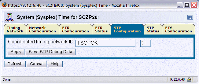
Figure 3-10 System (Sysplex) Time: STP Configuration tab
The response to the z/OS DISPLAY ETR command, message IEA282I now includes the CTN ID (Example 3-14).
|
Note: The menu shown in Table 3-9 on page 123 is for a server that has been previously configured in an ETR network. If you add a new server to a Mixed CTN you must enter both the CTN ID and the ETR ID.
|
Example 3-14 D ETR command and response
D ETR
IEA282I 14.39.57 TIMING STATUS 292
SYNCHRONIZATION MODE = ETR
CPC PORT 0 <== ACTIVE CPC PORT 1
OPERATIONAL OPERATIONAL
ENABLED ENABLED
ETR NET ID=31 ETR NET ID=31
ETR PORT=05 ETR PORT=05
ETR ID=00 ETR ID=01
THIS SERVER IS PART OF TIMING NETWORK ITSOPOK -31
Because the Sysplex Timer is the time source in a Mixed CTN, at least two servers or CFs should be in ETR Timing mode (stratum 1) in order to avoid a single point of failure.
For the same reason, if stratum 2 servers or CFs are configured in the Mixed CTN, each should be connected to at least two stratum 1 servers or CFs, with at least two coupling links to each stratum 1 server or CF.
The same recommendation applies to any planned stratum 3 servers in the Mixed CTN. Each stratum 3 server should be connected to at least two stratum 2 servers or CFs.
When more than two servers or CFs are configured in a Mixed CTN, servers beyond the two recommended stratum 1 servers can be individually configured in STP timing mode (stratum 2). Changing the timing mode for a given server or CF is done by disabling its ETR ports using the System (Sysplex) Time ∅ ETR Configuration tab, as shown in Figure 3-11. Enabling the ETR ports switches the server or CF back to ETR Timing mode.
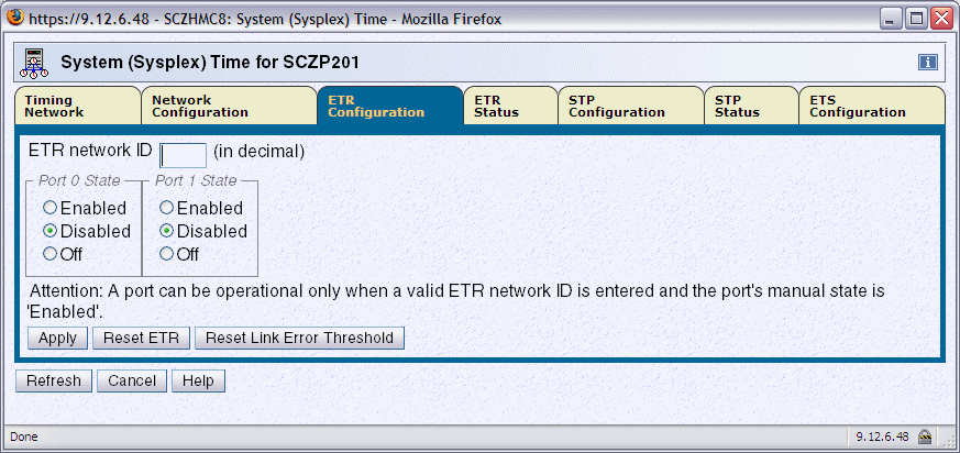
Figure 3-11 ETR Configuration tab: port enabled or disabled
3.2.2 Configuring an STP-only CTN
The sequence of steps in configuring an STP-only Coordinated Timing Network depends on whether it is a new STP-only installation or a migration from a Mixed to an STP-only CTN. The overall procedure consists of the following steps:
1. Configure an external time source (optional).
This optionally applies to both a new install and a migration from a Mixed to an STP-only CTN.
2. Set the CTN ID.
This applies only to an STP-only new installation.
3. Initialize the time.
This is only necessary for an STP-only new install. It includes:
– Set time zone.
– Set leap seconds.
– Set date and time.
4. Activate the STP-only CTN.
This is necessary for both an STP-only new install and a migration from a Mixed to an STP-only CTN.
Configuring the external time source (ETS)
To maintain time accuracy, both the Sysplex Timer and STP support connection to an external time source. Using an ETS, regular adjustments can be performed either manually or automatically.
In a Mixed CTN, if the Sysplex Timer has an external time source configured, it will be used and timing accuracy will be maintained as per the ETR network that was in place prior to the migration.
In an STP-only CTN the Sysplex Timer is no longer used. If an external time source is to be used, it must first be configured.
The System z10 and System z9 with driver 67L with the latest MCL level offer three choices for the ETS:
•A dial-out function with an HMC connected modem
•Synchronization to an NTP server connected to the Support Element LAN
•Synchronization to an NTP server with pulse per second (PPS) output connected to the SE LAN and the ETR card
The System z9 pre-driver 67L, z990, and z890 can only use the dial-out function, but can participate in an STP-only CTN where the CTS is synchronized to an NTP server.
Dial out from Hardware Management Console
Figure 3-12 shows the ETS Configuration tab from the System (Sysplex) Time task when the Use dial out if configured on Hardware Management Console radio button is selected.
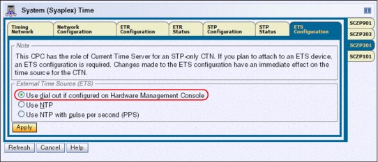
Figure 3-12 ETS configuration tab: use dial out on the HMC selected
The HMC dials out to the time service selected. To configure the dial-out telephone connection on the HMC select Service Management group ∅ Customize Outbound Connectivity. Check the Enable local system as call-home server box.
On the External Time Source tab, check Allow external time source dialing using the local modem and configure the protocol (Figure 3-13).
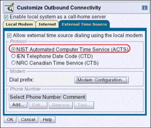
Figure 3-13 Customize Outbound Connectivity: External Time Source tab
To perform adjustments to the dial-out ETS automatically on a scheduled basis, the scheduled operations for the specific server must be customized. The function is established on the Hardware Management Console using customize scheduled operations in the Operational Customization menu. Selecting New on the Option tab guides you to a selection menu, shown in Figure 3-14.
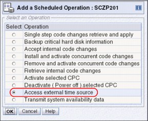
Figure 3-14 Add a Scheduled Operation for external time source access
On the Access external time source panel, specify when the operation is to take place. Set up a repeated scheduled operation. Depending on the time accuracy requirement, select one or more days that the ETS should be contacted. Use the option to repeat indefinitely to make sure that the scheduled operation never expires.
|
Note: In the case of an ETS dial-out failure a hardware message will be posted on the HMC.
|
Network Time Protocol (NTP) server
Selecting the Use NTP radio button displays the NTP Time Server Information table, shown in Figure 3-15. When at least one Configured check box is selected, it indicates that the IP address or web address entered should be used as the NTP server address.
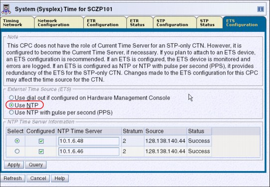
Figure 3-15 ETS Configuration tab: NTP w/o PPS
The use of a web address requires that the SE be customized with Domain Name Services (DNS) enabled. Use the task Customize Network Settings ∅ Name services in the Support Element Console Application. Refer to the manual Support Element Operations Guide for each server for information about how to customize network settings for the SE.
The Query button tests the IP connectivity and fills in the Stratum, Source, and Status table fields for the corresponding NTP server. The NTP configuration takes effect when Apply is clicked.
The Source field contains a description of the time source for the NTP server provided as information by the NTP server.
When two NTP servers are configured, it is the user’s responsibility to chose the preferred NTP server by selecting the appropriate Select radio button. This NTP server is called the selected NTP server. The other NTP server is called the non-selected NTP server. The SNTP client compares the quality of both NTP servers and informs the user in case the selected NTP server has a stratum level that is lower in the hierarchy than the non-selected NTP server (a stratum 1 server is usually a better choice than a stratum 2, and so forth), or if the time obtained from the selected NTP server is less accurate than the non-selected NTP server.
Network Time Protocol (NTP) server with pulse per second (PPS)
Selecting the Use NTP with pulse per second (PPS) radio button also displays the NTP Time Server Information table, shown in Figure 3-16. In addition, a PPS Port column is shown, indicating the NTP server to PPS port correlation.
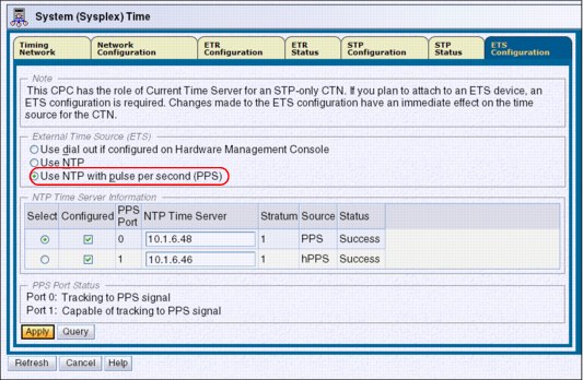
Figure 3-16 ETS Configuration: NTP with pulse per second
PPS Port 0 corresponds to the NTP server, defined in the upper row of the NTP Time Server Information table. The PPS output of this NTP server must be connected to PPS port 0. PPS Port 1 corresponds to the NTP server, defined in the lower row of the NTP Time Server Information table. The PPS output of this NTP server must be connected to PPS port 1 on the System z server.
The physical location of ETR card 0 and ETR card 1 is documented in the Installation Manual Physical Planning documentation for each server (see “Related publications” on page 201).
The user is responsible for entering the IP address matching the PPS output port on the NTP server unit.
The NTP with pulse per second configuration takes effect when Apply is clicked. STP creates a time adjustment to steer the Current Server Time to the time provided by the NTP server and the pulses received by the corresponding PPS port.
On the ETS configuration tab, the PPS Port Status section is displayed below the NTP Time Server Information. Information in this section is only displayed for servers configured with the PTS or BTS role. When all four PPS ports are configured, the status of all four reveals which port is tracking to the PPS signal, which ports are capable of tracking to the PPS signal, and which ports are in a state that do not allow use of PPS. The information is valid at the time that the status is displayed and must be refreshed if conditions change.
Setting the CTN ID
When an STP-only CTN is implemented, entering a CTN ID is required to define the CTN. The STP Network ID portion of the CTN ID is entered in the STP Configuration tab, as shown in Figure 3-17. The same CTN ID must be entered on every server that will participate in the STP-only CTN.

Figure 3-17 System (Sysplex) Time: STP Configuration tab
Initializing the time
When migrating from a Mixed CTN to an STP-only CTN, there is no need to initialize the time because the CTN inherits the following timing information from the Sysplex Timer:
•Date and time
•Leap second offset
•Time zone offset, including Daylight Saving adjustment
However, the time zone algorithm must still be defined before a daylight saving time (DST) schedule can be selected (see “Time zone offset adjustment” on page 111).
When an STP-only CTN is implemented without migrating from a Mixed CTN, time initialization is required to complete the CTN configuration process.
|
Important: Initializing the time must be done on the server that will become the Current Time Server for the STP-only CTN.
|
The Initialize Time button is accessed from the Network Configuration tab shown in Figure 3-42 on page 145. The Initialize Time button is only enabled prior to configuring the STP-only CTN. This is the case when an STP-only CTN is set up for the first time or if an STP-only CTN was previously deconfigured.

Figure 3-18 HMC workplace: System (Sysplex) Time, Network Configuration
Clicking Initialize Time displays the Initialize Time panel displayed in Figure 3-19. There are three radio buttons on the panel, each representing a task that must be completed before a Network Configuration can be applied for an STP-only CTN. The three tasks related to initializing the time are:
•Set leap seconds.
•Set time zone.
•Set date and time.
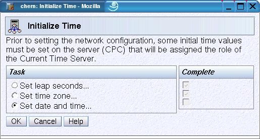
Figure 3-19 HMC workplace: Initialize Time
Set leap seconds
Introduction of the ETR architecture provided a means whereby TOD clocks could be set and stepped very accurately on the basis of an external UTC time source. As time becomes increasingly more accurate, consideration of the usage of leap seconds should be more carefully evaluated.
Since January 1, 1972, occasional corrections of exactly one second, called a leap second, have been inserted into the UTC time scale to keep UTC time within 0.9 second of UT1 at all times.
Depending on the applications and business requirements, leap seconds should be evaluated given the following circumstances:
•If there are specific accuracy requirements to provide UTC or GMT to the very second, at any instant, then leap seconds should be considered.
Some examples of such specific requirements might be legal or contractual requirements for time stamps to be within some tolerance of UTC Time, or if time stamps are used for time-dependent banking, scientific, or navigational purposes.
To account for leap second corrections, the total accumulated number of leap seconds since January 1972 must be entered when setting the time.
•Most sites have little awareness of leap seconds and ongoing leap second adjustments, and therefore this setting can probably be ignored. If there are no specific requirements for leap seconds then specify a leap second value of zero.
When a leap second is announced, it is inserted as the 61st second (or subtracted as the 60th second) of the last minute of the month of June or December. When a leap second is added, the sequence of time stamps looks like the one illustrated in Example 3-15.
Example 3-15 Leap second sequence: changing from 23 to 24
STCK (STP time) UTC time (= STCK - leap seconds)
00:00:20 23:59:57
00:00:21 23:59:58
00:00:22 23:59:59 -> Dec 31st
00:00:23 23:59:60 -> Dec 31st leap second
>> leap seconds changed from 23 to 24 <<
00:00:24 00:00:00 -> Jan 1st
00:00:25 00:00:01
00:00:26 00:00:02
When the leap second offset occurs, z/OS is interrupted just as it is for Daylight Saving Time offset changes if STPMODE YES was specified in the CLOCKxx member of PARMLIB. The offset value is updated if STPZONE YES was also specified in the CLOCKxx member.
Applications do not see a time stamp of 23:59:60, but the extra second is added to the day, thus keeping the z/OS image aligned instantly with the world time standard, UTC.
|
Note: Making a positive leap second change causes z/OS to spin for the amount of the leap second change. This is to avoid duplicate UTC time stamps. However, a large positive change in leap seconds can cause a system outage, as z/OS must spin for that amount of time to avoid duplicate UTC time stamps.
|
Most sites have little awareness of leap seconds and ongoing leap second adjustments. Therefore, this setting can probably be ignored. If there are no specific requirements for leap seconds, then you should specify a leap second value of zero.
An external time source (ETS) supplies UTC time. When STP synchronizes with the ETS it steer STP time such that UTC time is synchronized with the ETS. If leap seconds are not used or a leap second adjustment is not scheduled when a leap second is inserted into UTC then the UTC time of the CTN will be wrong by one second. STP will steer to the correct UTC time but steering take seven hours to complete. Sites that have a requirement for correct UTC time must use leap seconds to avoid this seven hour period while UTC time gets steered to the correct UTC time when a leap second is inserted.
STP accepts local time provided by the user, the UTC time from an external time source (ETS), or a delta value, and calculates the value of the Coordinated Server Time using the leap seconds and time zone offset values specified. The leap seconds value is sent to STP when OK is clicked. Table 3-3 lists the current leap second offset.
Table 3-3 Current leap second offset
|
Leap second offset
|
Date applied
|
|
+23 seconds
|
December 31, 2005 (scheduled +1 increment)
|
|
+24 seconds
|
December 31, 2008 (scheduled +1 increment)
|
|
+25 seconds
|
June 30, 2012 (scheduled +1 increment)
|
If a leap seconds value is specified during the initialize time process, the appropriate international time bureau should be monitored to determine when future leap seconds might occur. As they occur, the accumulated leap seconds value should be changed on the HMC to maintain accurate UTC time without having to steer for a new leap second over a seven hour period.
|
Important: Table 3-3 contains leap second offset values in place at the time of writing of this book. (The most recent leap second change was June 30st, 2012, as indicated in Table 3-3.) Check with the official agencies regarding the current leap second offset and future leap second scheduling before making any changes to the system.
The agency that is responsible for making leap seconds announcements is International Earth Rotation and Reference Systems (IERS) ServiceOne of the official agencies is the United States Naval Observatory. See:
You can also subscribe for leap seconds announcements at:
|
Set time zone
The panel shown in Figure 3-20 is used to set initial time zone parameters for the CTN. The current time zone is set by selecting an entry from the Time zone drop-down list. The values entered are sent to STP when OK is clicked.
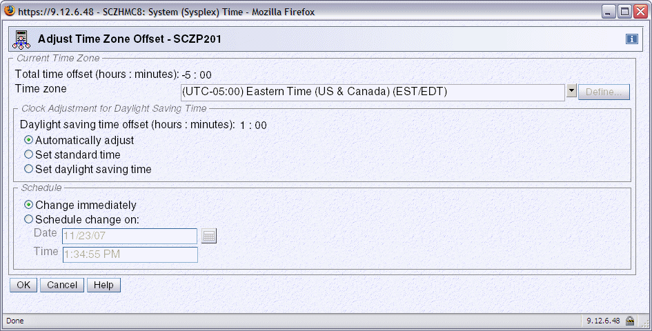
Figure 3-20 HMC workplace: Adjust Time Zone Offset
Clicking the Time zone drop-down arrow displays a list of all the supported time zones. Each of the supported time zone entries has a defined offset from UTC and the Daylight Savings Time offset for that entry if applicable.
The following Daylight Savings Time information is obtained by STP when you select a time zone entry:
•Daylight Saving time offset
•Daylight Saving automatic adjustment information (optional)
– Daylight Saving date and time start algorithm
– Daylight Saving date and time end algorithm
Automatically adjust is selected by default when the time zone selected supports automatic adjustment of daylight saving time. Otherwise, this button is disabled. Even if automatic adjustment is supported, the user still has the option of selecting Set standard time or Set daylight saving time.
If automatic adjustment for daylight saving time is not supported by the selected time zone, you must decide whether the current date and time are in a daylight saving period and select the Set standard time or Set daylight saving time radio buttons accordingly.
User-defined time zone
If a supported time zone entry that meets the requirements cannot be found, then one of the five user-defined time zones (that is, UD1 to UD5) can be used to define the desired time zone. If a user-defined time zone entry is selected, the Define button is enabled. It is used to display the Define Time Zone Algorithm panel shown in Figure 3-21.
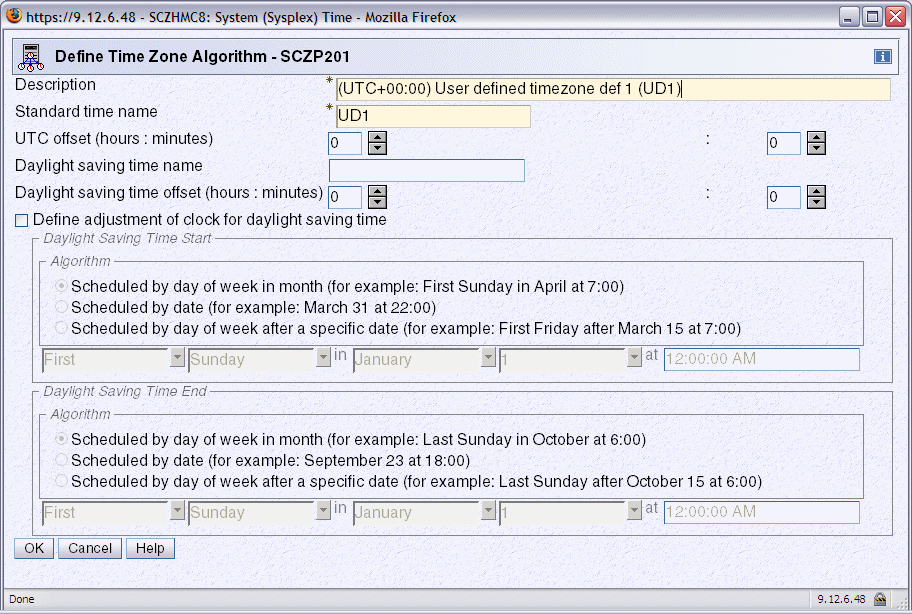
Figure 3-21 HMC workplace: Define Time Zone Algorithm
The Description (maximum of 80 characters) and Standard time name fields (maximum of 4 characters) must be entered, otherwise an error message appears when OK is clicked. The standard time name is an abbreviation displayed on various panels to differentiate standard time from daylight saving time.
The UTC offset must be entered in +/- hours and minutes and ranges from -14 to +14 hours.
Also, if the time zone is subject to daylight saving adjustments, then the daylight saving time name and daylight saving offset must be specified. Optionally, algorithms for daylight saving time start and daylight saving time end can be defined to support automatic clock adjustment by selecting the Define adjustment of clock for daylight saving time option. The algorithm is saved when OK is clicked, but it is not sent to STP until OK is clicked on the Adjust Time Zone Offset panel.
Set date and time
The final task in the sequence is to initialize the date and time. Three different methods are provided. The most appropriate method for the site should be chosen.
•If an ETS is not planned for the CTN, Set date and time is clicked, allowing you to specify the local date and time.
•An external time source can be used to set the time to one of the ETS options configured for STP. Once configured, the ETS is used to calculate the difference between the server’s time and UTC. The resulting delta value is not displayed to the user, but instead passed directly to STP when OK is clicked.
•A delta value can be specified through selection of Modify time by delta to set date and time. The value specified is either positive (default) or negative and is entered in the +/-hh:mm:ss.mmm format.
Irrespective of the method chosen, STP uses the information to calculate the Coordinated Server Time and set the server TOD clock when OK is clicked.
At this point all the tasks have a check mark in the Complete column. On the Network Configuration tab, the Apply button is enabled, allowing the network configuration to be defined.
The Coordinated Server Time will be passed to other participating servers in the CTN when the server roles and the Current Time Server are configured and activated using the Network Configuration tab. Once the STP-only CTN is configured, the Initialize Time button is disabled.
Activating the STP-only CTN
This is necessary for both an STP-only new install and a migration from a Mixed to an STP-only CTN.
Activation of an STP-only CTN is done by assigning a Current Time Server.
The configuration change is done from the Network Configuration tab, shown in Figure 3-22. The change must be initiated from the server that will become the CTS. Although not mandatory, we recommend that the Backup Time Server and Arbiter also be assigned at this stage. If the STP network consists of fewer than three servers, the Arbiter remains unassigned.
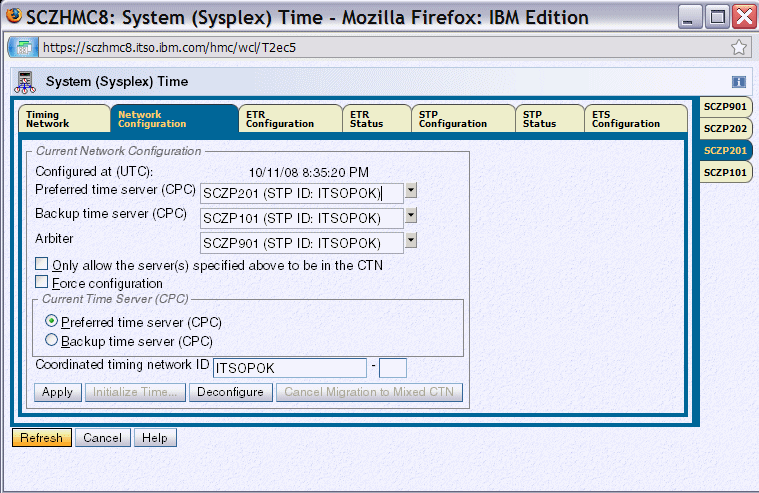
Figure 3-22 System (Sysplex) Time: Network Configuration tab
When the configuration is applied, the assignment of the Current Time Server (CTS) globally transitions all servers with the same CTN ID to STP timing mode. The Current Time Server specified must be either the Preferred Time Server or the Backup Time Server. Either role is able to provide backup for the CTS. Furthermore, the PTS has the capability to automatically re-takeover the CTS role within a recovery scenario once the PTS is back in operational state. For this reason it is a good idea to assign the Current Time Server to the Preferred Time Server because the Backup Time Server cannot do an automatic re-takeover after a recovery action.
If the new STP-only CTN consists of only one server, it is a good idea to select the Only allow the server(s) specified above to be in the CTN option. This prevents the server from getting deconfigured when doing a power-on reset or power off/on. However, this option also limits the CTN to one server, unless the option is deselected, which can be done concurrently at any time.
|
Note: The Only allow option also applies to a two-CEC CTN. It prevents servers from being deconfigured when a site power off affects both the PTS and the BTS.
|
If the request is for a new STP-only installation, the Force configuration check box must be selected (see “Force configuration” on page 130).
If the request includes a migration from a Mixed CTN, the following changes are also triggered when the CTS assignment is applied:
•The ETR Network ID is removed from the CTN ID for all servers in this CTN. This operation migrates the Mixed CTN to an STP-only CTN with immediate effect.
•All ETR ports are disabled for servers that were still in ETR timing mode. The operation transitions all servers in this CTN into STP timing mode.
When the activation is complete, the z/OS DISPLAY ETR command now identifies the timing network as an STP-only CTN, as shown in Example 3-16.
Example 3-16 DISPLAY ETR command
D ETR
IEA386I 18.06.54 TIMING STATUS 216
SYNCHRONIZATION MODE = STP
THIS SERVER IS A STRATUM 2
CTN ID = ITSOPOK
THE STRATUM 1 NODE ID = 002097.E26.IBM.02.00000001DE50
THIS IS THE BACKUP TIME SERVER
NUMBER OF USABLE TIMING LINKS = 7
3.3 Managing the time
This section discusses the following time modifications within a CTN and the operational requirements:
•Time adjustment in an STP-only CTN
•Offset adjustments in an STP-only CTN
•Changes in local time
•Sysplex and multiple time zones
3.3.1 STP time adjustment
Without regular adjustment, the time on the Current Time Server drifts from its initial setting because of the frequency drift of the oscillator used to step the TOD clock. This might not meet time accuracy requirements. Therefore, adjustments might need to be made on a regular basis.
Adjustments of time can be performed at the Current Time Server through use of the Adjust Time button on the Timing Network tab. This can be done manually or by referencing an external time source.
In a Mixed CTN, time adjustment is the same as in an ETR network. The Sysplex Timer adjusts the time of the stratum 1 servers in the Mixed CTN. Since stratum 2 servers in the Mixed CTN are synchronized to the stratum 1 servers, and stratum 3 servers are synchronized to the stratum 2 servers, time adjustments are gradually propagated through the entire Mixed CTN.
In an STP-only CTN, time adjustments are only permitted from the Current Time Server, which propagates the adjustments through the STP-only CTN.
The following adjustments are possible:
•Adjustment steering
STP supports adjustment steering, which allows the time at the Current Time Server to be changed by up to +/- 60 seconds. This is an improvement over the Sysplex Timer that supported a maximum adjustment of +/- 4.999 seconds. Adjustments greater than 60 seconds can be implemented in multiple increments of +/- 60 seconds. This can take considerable elapsed time to achieve.
The offset specified is gradually incorporated into the standard timing messages in small enough increments or decrements that the operating systems, subsystems, and applications are unaware that time is speeding up or slowing down.
The input of the offset to be steered out is done either manually or through the ETS.
|
Note: In an STP-only CTN, the adjustment steering rate is approximately one second every 7 hours. This compares to an ETR network or Mixed CTN where the Sysplex Timer provides a steering rate of approximately one second every 11 hours.
|
•Base steering
There is another time-steering method built into the STP facility that works in a similar fashion to the adjustment steering. This is an automatic function requiring no user control. This is known as base steering, which is performed at the Current Time Server and requires an ETS.
By comparing the time obtained from subsequent accesses of a configured ETS with the corresponding Coordinated Time Server values, STP can compute the amount of drift that has occurred between the events. This represents the inherent inaccuracy of the Current Time Server oscillator over time. With this information, STP can automatically introduce a compensation offset into the STP timing messages by additional steering to counter the drift. As a result, the Current Time Server self-corrects over time so that the offset returned from future ETS accesses approaches zero as greater accuracy is achieved.
Base steering is only performed if the NTP server is a stratum 1. The stratum level of the NTP server can be seen in the Network section of the Timing Network panel as shown in Figure 3-23 on page 108.
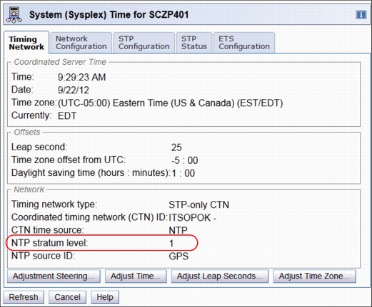
Figure 3-23 NTP server stratum level
Table 3-4 STP clock adjustment summary
|
|
Dial-out or NTP server access adjustment
|
Manual adjustment
|
Manual set
|
|
Adjustment steering
|
Yes
|
Yes
|
No
|
|
Base steering
|
Yes, after multiple ETS accesses
|
No
|
No
|
|
Note: Once a CTN is configured, the only way to set the date and time is to deconfigure the CTN and then go through the process to initialize the time again. Refer to the Server Time Protocol Implementation Guide, SG24-7281, for details.
|
The Adjust Time button is not available when the CTN time source is NTP with pulse per second. Since STP utilizes PPS input every second, manual adjustment is disabled.
3.3.2 STP offset adjustments
The STP timing message includes the following:
•Coordinated Server Time
•Leap second offset
•Time zone offset
•Daylight saving time offset
These values are transmitted from the Current Time Server to all the servers in the CTN. How the z/OS system image uses these values is dependent on options specified in the TIME macro in combination with options specified in CLOCKxx at IPL.
Different time results can be received depending on the options specified in the TIME macro, as shown in Table 3-5.
Table 3-5 TIME macro options
|
|
TIME macro with
ZONE=LT
|
TIME macro with
ZONE=UTC
|
TIME macro with
STCK
|
|
Include TOD in result
|
Yes
|
Yes
|
Yes
|
|
Include leap second offset
|
Yes
|
Yes
|
No
|
|
Include time zone offset
|
Yes
|
No
|
No
|
In addition, the parameters specified in the CLOCKxx member at IPL determine where these values are obtained. Table 3-5 indicates the behavior of a z/OS system on a server in ETR timing mode based on the CLOCKxx settings.
Table 3-6 z/OS system on a server in ETR timing mode
|
|
ETRMODE=NO
ETRZONE=NO
|
ETRMODE=YES
ETRZONE=NO
|
ETRMODE=YES
ETRZONE=YES
|
|
Step TOD to Sysplex Timer.
|
No
|
Yes
|
Yes
|
|
Include leap second offset from Sysplex Timer.
|
No
|
Yes
|
Yes
|
|
Include time zone offset from ETR.
|
No
|
No
|
Yes
|
|
Include time zone offset from CLOCKxx.
|
Yes
|
Yes
|
No
|
|
Allow local time adjustment via z/OS SET commands.
|
Yes
|
Yes
|
No
|
Table 3-7 z/OS system on a server in STP timing mode
|
|
STPMODE=NO
STPZONE=NO
|
STPMODE=YES
STPZONE=NO
|
STPMODE=YES
STPZONE=YES
|
|
Step TOD to Current Time Server.
|
No
|
Yes
|
Yes
|
|
Include leap second offset from Current Time Server.
|
No
|
Yes
|
Yes
|
|
Include time zone offset from Current Time Server.
|
No
|
No
|
Yes
|
|
Include time zone offset from CLOCKxx.
|
Yes
|
Yes
|
No
|
|
Allow local time adjustment via z/OS SET commands.
|
Yes
|
Yes
|
No
|
Leap second offset adjustment
Adjustments are only necessary (if leap seconds are used) if the applications require precise synchronization accuracy to UTC. Examples of such specific requirements might be legal or contractual requirements for time stamps to be within tolerance of UTC Time, or if time stamps are used for time-dependent banking, scientific, or navigational purposes.
Periodically, the International Earth Rotation and Reference Systems Service in Paris advises that a leap second adjustment, which might be either positive or negative, is required to be introduced into civil time. At the time of this writing, there have been 24 leap seconds introduced into civil time since 1972, the last being December 31, 2008. Each of the leap seconds introduced so far has been positive. However, it is theoretically possible to have a negative leap second adjustment.
|
Note: Leap seconds are automatically built into UTC time obtained from an external time source. Any leap second offset that is defined is taken into account when calculating the delta between the Current Time Server and the time received from the ETS. This is required to prevent double accounting.
If the ETS is used to incorporate an additional leap second into the Current Time Server TOD, then be aware that the requirement that leap second adjustments should occur at the same time worldwide has been breached. This is because TOD adjustments via the ETS are implemented over a period of time via adjustment steering rather than immediately.
If leap seconds are used, the adjust leap seconds facility should be used to ensure that the new offset is applied as a single adjustment at the correct time.
|
Typically, adjustments to the leap second offset are scheduled to be applied on either June 30th or December 31st. However, the offset adjustment might be scheduled for a particular date depending upon the requirements.
A positive leap second is inserted after UTC 23:59:59, as UTC 23:59:60, then UTC 00:00:00 would occur as normal. Note that 23:59:60 will never be made visible to users of the TOD clock. A negative leap second is potentially possible (however, it has not occurred to date) and is implemented by excluding UTC 23:59:59.
When the leap second offset occurs, z/OS is interrupted just as it is for DST offset changes if STPMODE YES was specified in the CLOCKxx member of SYS1.PARMLIB. The offset value is updated if STPZONE YES was also specified.
The Adjust Leap Second panel is used to apply the leap second offsets when they become available. Clicking Adjust Leap Seconds from the Timing Network tab on the Current Time Server displays the panel shown in Figure 3-24.
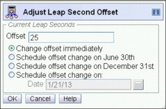
Figure 3-24 System (Sysplex) Time, Timing Network, Adjust Leap Second Offset
|
Important: Never make leap seconds adjustments with more that one second at a time. A large positive change in leap seconds can cause a system outage, as z/OS must spin for that amount of time to avoid duplicate UTC time stamps.
|
When the Adjust Leap Second Offset panel is displayed, the current leap second offset in effect for the STP-only CTN value is displayed in the Offset box. This value is either inherited from the Sysplex Timer during the migration process from an ETR network or set during the Initialize Time function.
|
Important: Leap second adjustments occur at the same time worldwide, so it must be understood when UTC 23:59:59 will occur in the particular time zone, because this is when a scheduled leap second offset adjustment will be applied.
|
Time zone offset adjustment
The Offsets section of the Timing Network tab displays the current time zone offset information for an STP-only CTN.

Figure 3-25 Timing Network tab following a migration from Mixed CTN to STP-only
If the Offsets section displays a Total time (hours : minutes) field as shown in Figure 3-25, a specific time zone is not set. This only occurs when the time zone information (incorporating a Daylight Saving offset, if any) has been inherited from a Sysplex Timer during a migration process. The value displayed in the Total time (hours : minutes) field is retained until a time zone is selected.
The Total time offset field is no longer displayed once a time zone selection has been applied (Figure 3-26).

Figure 3-26 Timing Network tab; after adjusting the time zone
Following a migration to STP-only CTN, a Current Time Zone must be defined before the automatic clock adjustment for daylight saving time can be enabled.
|
Note: During a migration process from Mixed to STP-only CTN, only the time zone offset (including daylight saving offset adjustment) is inherited from a Sysplex Timer, but no time zone definition is made.
|
The Adjust Time Zone button on the Timing Network tab is used to define or modify a time zone setting applicable for the environment. This displays the Adjust Time Zone Offset panel shown in Figure 3-27.
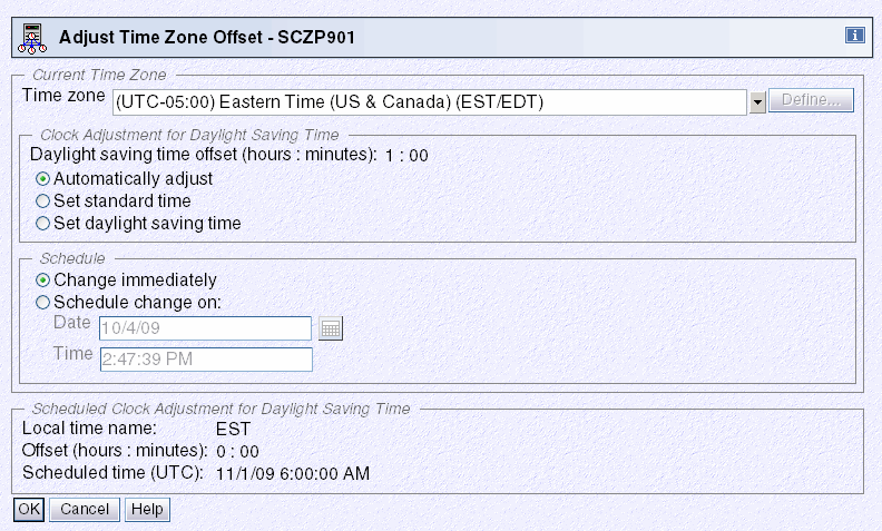
Figure 3-27 HMC workplace: System (Sysplex) Time, Timing Network, Adjust Time Zone Offset
Select one of the supported time zones that are provided by default or use one of the five user-defined time zones to customize an entry to specifically meet the requirements.
Supported time zone offsets
A number of supported time zone entries are provided by default. Each of these entries has a defined offset from UTC.
|
Note: The time zone on the System z10 or System z9 Support Element is independent of the time zone set for the CTN. The same is also true for the HMC. It is possible to have a different time zone at each Support Element, the HMC, and for the CTN.
|
In addition, each entry can optionally have a time zone algorithm defined that contains the following daylight saving information:
•Daylight saving offset
•Daylight saving automatic adjustment information (optional):
– Daylight saving date and time start algorithm
– Daylight saving date and time end algorithm
If the selected time zone supports automatic adjustment by providing a time zone algorithm with the necessary start and end information, then the Automatically adjust radio button can be used to activate automatic adjustment for the site.
Alternatively, the time zone might not support automatic adjustment, or is handled manually. In this case select either Set standard time or Set daylight saving time to indicate whether a daylight saving period is active when the selected time zone is activated.
The Scheduled Clock Adjustment for Daylight Saving Time section is displayed if an adjustment has been scheduled either automatically as the result of an Adjust Time Zone offset algorithm or manually through the schedule change on facility.
|
Tip: There is no direct way to review the time zone algorithm that might optionally be part of a supported time zone entry. Therefore, there is no direct way to verify that the daylight saving time offset entry for the time zone will meet the requirements. However, this can be done indirectly by applying the time zone offset entry for the time zone with automatically adjust and then reviewing fields in the Schedule Clock Adjustment for Daylight Saving Time section for applicability correctness in relation to the next time zone adjustment.
|
DST changes implemented by a government authority
An example of this is the USA Energy Policy Act of 2005 that changed daylight saving time in the USA in 2007.
For an ETR network or a Mixed CTN, a DST offset must be scheduled at the appropriate time at the Sysplex Timer console. For an STP-only CTN, which has the option of automatically scheduling DST, support for the new daylight saving time start and end dates are available provided that the server has the correct level of microcode.
Future DST changes implemented by any governmental authority might require MCL updates. Make sure to keep the server MCLs as up to date as possible.
User-defined time zone offsets
If a supported time zone entry that meets the requirements cannot be found, then one of the five user-defined time zones (that is, UD1 to UD5) can be used to define the desired time zone. If a user-defined time zone entry is selected, the Define button is enabled. It is used to display the Define Time Zone Algorithm panel shown in Figure 3-28.
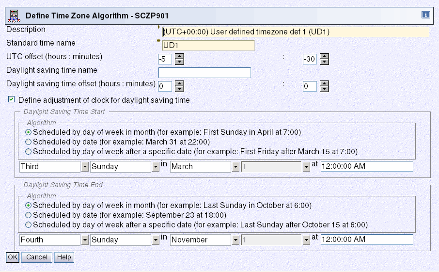
Figure 3-28 HMC workplace: Define Time Zone Algorithm
The Description (maximum of 80 characters) and Standard time name fields (maximum of 4 characters) must be entered, otherwise an error message appears when OK is clicked. The standard time name is an abbreviation displayed on various panels to differentiate standard time from daylight saving time.
The UTC offset must be entered in +/- hours and minutes and ranges from -14 to +14 hours.
Also, if the time zone is subject to daylight saving adjustments, then the daylight saving time name and daylight saving offset must be specified. Optionally, algorithms for daylight saving time start and daylight saving time end can be defined to support automatic clock adjustment by selecting the Define adjustment of clock for daylight saving time option. The algorithm is saved when OK is clicked, but it is not sent to STP until OK is clicked on the Adjust Time Zone Offset panel.
3.3.3 Changes in local time
z/OS allows the user to obtain either STCK time, UTC time, or local time depending on their requirements. The difference between UTC time and local time is usually the time zone offset under normal circumstances. The time zone offset can be managed at the z/OS level by specifying the ETRZONE=NO and STPZONE=NO options in the CLOCKxx member. The relevant option applies depending on whether the server is in ETR timing mode or STP timing mode.
When this is done, the TIMEZONE parameter in the CLOCKxx member is used to set the time zone offset at IPL, and a number of z/OS SET commands can be used to dynamically adjust the offset when required. Similarly, the coupling facility supports the concept of time zone offset and allows dynamic modification of the time zone offset via a command.
z/OS commands
On a z/OS system, local date and time can be modified dynamically. The ability to do this is dependent on what options have been specified in the CLOCKxx member at IPL, as shown in Table 3-8.
Table 3-8 z/OS time adjustment through command cross-reference
|
|
Adjust time via z/OS command
|
||
|
Local time
ZONE=LT
|
UTC time
ZONE=UTC
|
STCK time
STCK
|
|
|
ETRMODE=NO, ETRZONE=NO
|
Yes
|
Yes1
|
Yes1
|
|
ETRMODE=YES, ETRZONE=NO
|
Yes
|
No
|
No
|
|
ETRMODE=YES, ETRZONE=YES
|
No
|
No
|
No
|
|
STPMODE=NO, STPZONE=NO
|
Yes
|
Yes1
|
Yes1
|
|
STPMODE=YES, STPZONE=NO
|
Yes
|
No
|
No
|
|
STPMODE=YES, STPZONE=YES
|
No2
|
No
|
No
|
|
1. UTC time cannot be changed by a z/OS command. It can be modified during the IPL process in response to message
IEA888A [UTC DATE=yyyy.ddd,CLOCK=hh.mm.ss] LOCAL
DATE=yyyy.ddd,CLOCK=hh.mm.ss
REPLY U, OR UTC/LOCAL TIME
which is issued at IPL when OPERATOR PROMPT is specified in CLOCKxx with ETRMODE NO, STPMODE NO and SIMETRID not specified.
2. Any attempt to change the local time or date when the server is operating in STP mode generates message IEA279I: IEA279I ALL CLOCK RELATED SET COMMANDS ARE IGNORED WHEN IN STP MODE.
|
|||
DISPLAY TIME
This command can be used to display the local time and date, and the UTC time and date, as seen in Example 3-17.
Example 3-17 z/OS DISPLAY TIME command
D T
IEE136I LOCAL: TIME=hh.mm.ss DATE=yyyy.ddd UTC: TIME=hh.mm.ss DATE=yyyy.ddd
Under normal circumstances the difference between local time and UTC time is the time zone offset (incorporating daylight saving time offset, if any) applicable to the time zone.
SET DATE
This command is used to change the local date. The syntax is:
SET DATE=yyyy.ddd
It has the following restrictions:
•yyyy is the year. It must be in the range 1900–2042. The value specified must consist of four digits and must be within 70 years of the UTC date, otherwise the SET command is ignored.
•ddd is the day. It must be in the range 001–366 and meet leap year restrictions.
•The maximum date that can be specified is 2042.260.
SET CLOCK
This command is used to change the local time. The syntax is:
SET CLOCK=hh.mm.ss
This command is used in conjunction with the SET DATE command to set a maximum value of 23.53.47 on 2042.260. The server’s TOD clock is not updated by this command, nor is the logical TOD of the logical partition this z/OS image is operating on. The change made by this command is effective for the duration of this IPL only.
Also, z/OS does not change the date when the new time implies a change of date, so either use the DATE parameter or wait for time to pass midnight if the new time is for tomorrow.
SET RESET
This command causes the time zone offset to be reset to the value that was read in from the CLOCKxx member during IPL, causing the local date and time to be changed accordingly. The syntax is:
SET RESET
This annuls all previous SET DATE, SET CLOCK, and SET TIMEZONE commands and reestablishes the relationship local date and time = UTC date and time + time zone offset.
SET TIMEZONE
This command can be used to change the time zone offset to a different value from that specified at IPL via the TIMEZONE parameter in CLOCKxx. This automatically adjusts local date and time accordingly. The syntax is:
SET TIMEZONE={W|E}.hh[.mm]
The time zone offset direction is West (W) or East (E). West is defaulted if not specified. The value for hh must be between 00 and 15 and the value for mm must be between 00 and 59.
The daylight saving time changes can be handled manually using the SET CLOCK command rather than having it done automatically via Server Time Protocol (STP) or the Sysplex Timer. Using this method there is always a degree of error because the difference between the local time and UTC time will not exactly match the time zone offset that would have been achieved by updating the TIMEZONE statement in CLOCKxx and IPLing.
The new z/OS SET TIMEZONE command overcomes this problem by applying the correct offset value in the CVTTZ field, causing an exact time zone offset to be applied.
|
Tip: If the SET CLOCK command is used to change local time for daylight saving offset purposes, then use the SET TIMEZONE command instead for better accuracy.
Remember that if the time zone offset for daylight saving purposes is changed dynamically using either the z/OS SET CLOCK or the SET TIMEZONE commands, the TIMEZONE statement in CLOCKxx must be updated so that the new offset is not regressed at the next IPL.
|
Coupling facility commands
In a Parallel Sysplex environment, coupling facilities require time awareness to support CF request time ordering. The server TOD is used for this purpose.
Coupling facilities also support the concept of time zone offset, which is used only for the purpose of timestamping messages that are displayed on the console.
There is no CFCC command available to display time. However, all messages that appear on the CF console include a time stamp in local time format, which is the server TOD with the time zone offset applied. Therefore, the current local date and time at the CF console can be indirectly determined by entering any command (valid or invalid) and reviewing the time stamp in the resulting response.
Because the CF supports a local time format that incorporates the time zone offset, it also provides methods to both display the current time zone offset setting and to change it if required.
DISPLAY TIMEZONE
Use the CFCC DISPLAY TIMEZONE command to display the current time zone offset being used by the coupling facility. The syntax is:
DISPLAY TIMEZone
This produces a single line indicating how many hours and minutes the current time zone is east or west of Greenwich Mean Time (Example 3-18).
Example 3-18 CFCC DISPLAY TIMEZONE command
2006272 11:06:47 => display timezone
2006272 11:06:47 CF0271I Timezone is 04:00 West of Greenwich Mean Time
TIMEZONE
The CFCC supports a command allowing the time zone offset to be changed, if this is a requirement. The syntax is:
TIMEZone {0|hh|hh:mm|:mm} {East|West}
Use the command in Example 3-19 to adjust the local time as displayed in messages on the coupling facility console for the onset and removal of daylight saving time.
Example 3-19 CFCC TIMEZONE command
2006272 11:17:31 => timezone 05:00 west
2006272 11:17:31 CF0271I Timezone is 05:00 West of Greenwich Mean Time
Coupling facility implications at daylight saving time changes
When a CF image partition is activated and the server is using Server Time Protocol or a Sysplex Timer source, the CFCC uses only one of the following time offset options:
•The logical partition time offset specified in the image profile
•The TIMEZ offset
The TIMEZ offset overrides the logical partition time offset. Use the TIMEZ command for DST changes as described in the document at the following website:
3.3.4 Logical partition time offset
IBM System z servers support a function called logical partition time offset. Logical partition time offset3 support provides for the optional specification of a fixed time offset (specified in days, hours, and quarter hours) for each logical partition activation profile. The offset, if specified, is applied to the time that a logical partition receives from Server Time Protocol or a Sysplex Timer.
It is sometimes necessary to run multiple Parallel Sysplexes with different local times and run with the time set to TOD Clock LOCAL. This causes the results returned in the store clock (STCK) instruction to reflect local time. With logical partition time offset support, logical partitions on each server in a Parallel Sysplex that must do this can specify an identical time offset that shifts time in the logical partition sysplex members to the desired local time. The logical partition time offset value, if specified, is applied to the time value that a logical partition receives from the time source. The time zone offset and DST offset are independent of this parameter.
Remaining logical partitions on the servers can continue to participate in current date production Parallel Sysplexes utilizing the same STP messages or Sysplex Timers with the time provided by STP or the Sysplex Timers. This function is supported by all supported releases of z/OS.
Open the image profile of the image to be modified. From the General tab, select Logical Partition Time Offset from the Clock Type Assignment area (Figure 3-10).
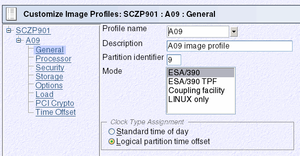
Figure 3-29 Clock Type Assignment: Logical partition time offset
A new selection becomes available on the left side of the panel, called Time Offset. Use the Time Offset window to set the offset, as seen in Figure 3-30.
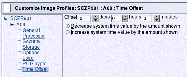
Figure 3-30 Time Offset
The settings available on the Time Offset window have the following meanings:
•Offset .
Type or spin to the number of days, hours, and minutes to be set as the offset from the time of day supplied by its time source. The offset can be in the following range:
– 0 to 999 days
– 0 to 23 hours
– 0, 15, 30, or 45 minutes
•Decrease system time value by the amount shown.
Select this choice to set the logical partition’s clock back from the time of day supplied by its time source by the number of days, hours, and minutes in the offset. Use this setting to provide a local time zone west of UTC.
•Increase system time value by the amount shown.
Select this choice to set the logical partition’s clock ahead of the time of day supplied by its time source by the number of days, hours, and minutes in the offset. Use this setting to provide a local time zone east of UTC or a date and time in the future.
3.3.5 Parallel Sysplex and multiple time zones
Some Parallel Sysplex installations have a requirement where different z/OS sysplex members are IPLed in different time zones. This is accomplished by:
•Having all sysplex members on a common time source with STPMODE YES or ETRMODE YES
•Not using STP or the Sysplex Timer to obtain time zone information, by specifying STPZONE NO or ETRZONE NO and TIMEZONE d.hh.mm.ss.
Alternatively, one group of sysplex members in a common time zone could use STP or the Sysplex Timer as the time zone source, using STPZONE YES or ETRZONE YES, while other sysplex members do not.
This section discusses how to create and manage the multiple time zone environment.
Create the multiple time zone environment
The example in this section reflects a consolidation of multiple sysplexes into a single sysplex. This in itself is not remarkable. What is unusual is the fact that the sysplex is supporting applications intended to operate in images that support different time zones.
The following issues are addressed when creating the environment:
•Software considerations
•Vendor software
•Staggered time zone setup considerations
Software considerations
Producing a sysplex with staggered time zone offsets introduces many peculiarities into the environment that not every installation or department is happy with. However, there might be business reasons why this configuration is favored, such as sysplex consolidation efforts or business consolidations. Some, but not all, of the peculiarities are:
•SMF considerations
SMF records contain local time. If SMF records from two systems are used for accounting purposes, the data is not accurate. For example, assume that a job is submitted on logical partition 1A, getting a job reader start time in one time zone, and the job executes on another image, getting job start and end times in the other time zone.
•RMF™ considerations
RMF displays and reports are suspect for the same reasons cited under SMF.
•OPERLOG considerations
Although the records are ordered by UTC (GMT) time stamps, they are displayed with local time offsets. For example, in a merged OPERLOG, messages from the two systems described appear to be out of sequence.
•JES2 time-sensitive command considerations
Some JES2 commands, such as $TA and $PJQ, have time-sensitive parameters that would cause actions to be taken at different times. For example, the commands would execute N hours earlier on one system than the other.
The system will function properly, but the external view will complicate the role of some people in the enterprise.
Vendor software
Since a sysplex allows work to be routed to any machine in the configuration, programs asking for local time can get a variety of answers depending on the server where the work was routed. To help in this situation there is software available that will provide an altered date and time to users, user applications, subsystems software, CICS® regions, and even specific transactions or terminal IDs.
One example is Application Time Facility for z/OS (formally TIC-TOC from ISOGON, Inc). To evaluate whether it is appropriate, start by consulting the following website:
Configuration considerations
To set up the sysplex with different time zones, there are considerations for z/OS and middleware. In-depth details are beyond the scope of this book, but some examples are mentioned here:
•CICS complex (CICSplex)
Although originally a full-function CICS ran in a single address space (region) in the z/OS environment, most CICS users are more accustomed to running multiple, interconnected CICS regions. Using the CICS Multi-region Operation (MRO) Intercommunication Facility, users can combine CICS regions into a complex of subsystems.
Using multi-region operations, CICS functions can be separated into individual regions, with the different types of CICS regions being classified as resource managers. With the latest enhancements to MRO, these CICS resource manager regions can reside in one or more z/OS images.
•CICSPlex® system manager
If there are servers in different geographical locations, are there connections between those processors, or are they managed as separate entities, each with its own workload? If these separate units exist in the enterprise, it is likely that there is a need to define multiple CICSplexes, and so manage the enterprise CICS systems as though they belonged to more than one enterprise.
Much of CICSPlex SM's activity is time-dependent. For example, it can be specified that a monitor definition or an analysis definition is to be active during a particular time period. CICSPlex SM does not require every instance in a single CICSplex to be running in the same time zone, and so must be able to accommodate any time zone differences between entities. Therefore:
– Whenever a time period definition (using the CICSPlex SM PERIODEF view) is created, a time zone must be specified in the definition. For example, a time period definition called MORNING can be created for the hours 08:00 through 11:59 Eastern standard time.
– A time zone must be specified for each CICSPlex SM address space (CMAS) in its data repository initialization job, EYU9XDUT. A permanent change to the CICSPlex SM address space time zone value can be made, even while the CMAS is running, via the CICSPlex SM user interface.
– A time zone must be established for each managed CICS system. When a CICS system is defined in a CICSPlex SM, the time zone in which the system is running can be specified. Alternatively, if no time zone is specified in the CICS system definition, the CICS system is assumed to be running in the time zone that is the default for the CICSPlex SM address space to which it connects. Allow the time zone of a managed CICS system to default to that of its CICSPlex SM address space. The time zone of a managed CICS system can be altered subsequently while the CICS system is running. Any change made in this way lasts for the lifetime of the CICS system, or until it is next changed, whichever is sooner.
– A time zone must be specified for every CICSplex when it is first defined. This time zone is used by the CICSPlex SM monitor function to determine the actual time at which the monitor interval for the CICSplex expires. The CICSplex time zone can be altered via the CICSPlex SM user interface.
Time zones are specified using single-character codes in the range B through Z. For example, code S represents Mountain Standard Time, code T represents Central Standard Time, and code C represents Eastern Europe Time. A complete list of the codes can be found in CICSPlex SM Setup and Administration - Volume 1. CICSPlex SM allows offsets (known as time zone adjustments) in the range 0 through 59 minutes to be specified to accommodate regions that are not running in the standard time zones. Also, daylight saving time can be specified.
Because multiple CICSPlex SM entities require a time zone to be specified, there is obvious potential for conflicting time zones to be specified. For example, it is possible that a CMAS and a CICS instance in the same CICSplex could be in different time zones. CICSPlex SM always honors the time zone of the CICS-managed application system. Suppose the following conditions exist:
•The time period definition time zone is S.
•The CICSPlex SM address space time zone is B.
•The CICS-managed application system time zone is C.
Time zone C is used by the CICS-managed application system, and the CMAS makes any necessary adjustments between time zones B, C, and S to ensure that the time zone is honored.
Manage the multiple time zone environment
|
Note: In this section, it might be preferable to use the new z/OS SET TIMEZONE command instead of the z/OS SET CLOCK command. Refer to “SET TIMEZONE” on page 116 for more information.
|
Since each sysplex member is in a different time zone, it is necessary to stagger Daylight Saving Time changes. Daylight saving time changes could be accomplished individually in each sysplex member using the SET CLOCK command from the z/OS console.
The cities used in the examples that follow include Sydney in the southern hemisphere (during summertime) and London, Atlanta, and Los Angeles in the northern hemisphere (using standard time).
Operational considerations
In Figure 3-31, each of the three cities accurately reflects the number of hours from the Greenwich meridian when Daylight Saving Time would be in effect in the southern hemisphere. That is, Sydney's TIMEZONE parameter is shown while Daylight Saving Time is in effect. London and Atlanta TIMEZONE parameters are shown with standard time in effect. Each hemisphere is changing the offset in different directions. When the southern hemisphere is changing from Daylight Saving Time to standard time (back), the northern hemisphere is changing from standard time to Daylight Saving Time (a forward change).
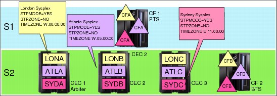
Figure 3-31 Staggered offset changes: one sysplex supporting multiple time zones
When planning for Daylight Saving Time changes in different countries, remember that not all countries agree on which dates the switch will occur. In fact, each country's government might change the Daylight Saving Time switch dates from year to year. A country that has multiple time zones might have a different change date in each zone. In our example, however, assume that all countries are going either to Daylight Saving Time (London and Atlanta) or to standard time (Sydney) on the same arbitrary day.
Just to keep things interesting, assume that this sysplex is physically located in Los Angeles, California. Any z/OS images representing Pacific Standard Time in the USA are not depicted in Figure 3-31. However, assume that those images contain STPZONE YES and that STP is being used to obtain Daylight Saving Time offsets.
Table 3-9 Local standard time offsets
|
Sydney
|
London
|
Atlanta
|
Los Angeles
|
|
02:00 AM
|
04:00 PM
|
11:00 AM
|
08:00 AM
|
|
12:00 PM
|
02:00 AM
|
09:00 PM
|
06:00 PM
|
|
05:00 PM
|
07:00 AM
|
02:00 AM
|
11:00 PM
|
|
08:00 PM
|
10:00 AM
|
05:00 AM
|
02:00 AM
|
Which sysplex members (cities) change their offsets first? The answer is Sydney: SYDA, SYDB, and SYDC. Since a new day will dawn in Sydney prior to in London and Atlanta, Sydney changes first. The operators in Los Angeles must be at Sydney's z/OS console to enter the SET TIMEZONE command at the correct instant.
What is the local time in Los Angeles when Sydney's DST offset changes? Remember that Sydney is on DST in the southern hemisphere. Assuming that Sydney wants the offset changed at 02:00 a.m. Sydney time, the Los Angeles operator must enter the command at 08:00 a.m. After the offset change, Sydney's local time will be changed from 02:00 a.m. to 01:00 a.m. (back one hour).
Several hours later, the same thing must be done for the London sysplex members. Again, assuming that London will change the offset at 02:00 a.m. London time, the Los Angeles operator must enter the command at 06:00 p.m. The only difference is that the northern hemisphere is changing the offset in the opposite direction from Sydney. London is going from standard time to Daylight Saving Time (forward).
Sometime later, it is Atlanta's turn. Atlanta is also going from standard time to Daylight Saving Time. The Los Angeles operator must enter the SET CLOCK command on Atlanta's z/OS console at 11:00 p.m.
Finally, the offset for Los Angeles can be changed through the Server Time Protocol, Adjust time zone offset panel. These images have STPZONE YES in their CLOCKxx members.
|
Note: Each customer situation is different. Certain ones are much more complicated, and others less so. Planning and excellent communications with the user community are essential when Daylight Saving Time schedules is a prime concern.
For some countries, time zones are not aligned on hourly divisions. For example, the time zone might be E.07.30.00 or W.08.45.00.
|
After a SET CLOCK command has been entered, change the TIMEZONE parameter in the CLOCKxx member in each affected image to reflect the new DST offset. The next IPL uses the new TIMEZONE value, and z/OS recognizes the correct local time for that image.
3.4 Managing the CTN configuration
This section discusses tasks associated with operational changes to a CTN. It discusses the following topics:
•Changing the CTN ID
•Changing the Current Time Server
•Changing the server roles
•Deconfiguring a timing network
3.4.1 Changing the CTN ID
STP supports a change to the CTN ID in either a Mixed or STP-only CTN from one value to another. If, for example, the CTN ID contains a value that is no longer relevant to the company it can be changed dynamically without a CTN outage.
Considerations for a CTN ID change in a Mixed CTN
In a Mixed CTN, a CTN ID change can be made using the STP Configuration tab. However, the only field within the CTN ID that can be changed dynamically is the STP portion of the CTN ID. The second field (the ETR portion) requires an outage of all systems within the CTN to force this change. An individual change is necessary for every server in the CTN. No global change is possible.
|
Important: XCF tolerates a mismatch of the CTN ID between systems for a matter of seconds only. When the time limit is reached, those systems with inconsistent CTN IDs are varied out of the sysplex. Consequently, where multiple servers are involved, this is not a recommended operation because the time to individually perform the sequential actions might exceed the XCF time limit.
|
Considerations for a CTN ID change in an STP-only CTN
This is a global change made from the Network Configuration tab of the Current Time Server and applies to the entire CTN. The new CTN ID is propagated in a coordinated fashion to all servers within the CTN. The change must be made from the Current Time Server. Otherwise, the request is rejected.
During a CTN ID change, z/OS systems and coupling facilities running on the servers might not all recognize the CTN ID change at exactly the same time. This can cause an inconsistent timing source scenario to occur between various components in the sysplex until the new CTN ID has been fully implemented across the CTN.
This temporary condition is recognized, tolerated, and automatically resolved. During this period various timing-related error messages can be sent to the console and syslog by both XCF and XES as inconsistent CTN IDs between z/OS logical partitions and coupling facilities are detected, respectively.
3.4.2 Single-server or dual-server auto resume after power-on reset
One of the reasons to implement STP, even on a single System z server, is to provide the same time across heterogeneous platforms using NTP client support. When an STP-only CTN is formed of a single server, it is possible as part of normal operation to deactivate or power-on reset the single server that is in the CTN.
In such a configuration, the STP configuration is saved across PORs to eliminate the need to initialize the time and reassign the PTS role after each POR. This can be accomplished by selecting the Only allow the server(s) specified above to be in the CTN option, as shown in Figure 3-32.
|
Note: For brevity’s sake, the capability implemented by selecting Only allow the server(s) specified above to be in the CTN is referred to as the save configuration feature and CTNs for which this capability is selected are referred to as bounded CTNs.
|

Figure 3-32 Server SCZP201 configured in a single server STP-only CTN
The option is available in a CTN consisting of either a single server or two servers. Figure 3-33 shows the Network Configuration tab for a dual-server CTN.
|
Note: It should be noted that after a power-off/on sequence, the TOD value in the Current Time Server is initialized from the TOD values stored in its SE. If you previously configured an ETS, STP code does not perform an initialize time using the ETS, but automatically accesses the configured ETS and starts adjusting the time so as to maintain time accuracy. STP allows time adjustments up to +/- 60 seconds.
|

Figure 3-33 System (Sysplex) Time for SCZP101
When the option is checked, STP prevents any other server from joining the CTN. If you want to expand the single-server or dual-server CTN to three or more, you must deselect this option and click Apply before attempting to configure additional servers.
3.4.3 Changing the Current Time Server
STP supports dynamically changing the Current Time Server to a different server in an STP-only CTN, for example, for planned maintenance when there is a need to perform a disruptive action on the Current Time Server.
Before changing the CTS role, consider whether the Internal Battery Feature (IBF) is present. The CTS can take advantage of the IBF to provide improved recovery against a power outage (see 2.4, “Internal Battery Feature (IBF)” on page 57). If the IBF is installed on one or more servers in the CTN, reconfigure the CTS to a server that has the IBF installed, unless it interferes with other availability rules.
Changing the Current Time Server is done without disruption to the z/OS and coupling facility components within the CTN. The message IEA395I is issued (z/OS V1.11, rolled back to z/OS 1.10 and 1.9 with PTFs):
IEA395I THE CURRENT TIME SERVER HAS CHANGED TO THE cccccccccccc
Where cccccc is BACKUP or PREFERRED.
From z/OS you can determine which server is the Current Time Server by issuing a DISPLAY ETR command and checking which server is performing the stratum 1 role, as shown in Example 3-20.
Example 3-20 z/OS DISPLAY ETR command
D ETR
IEA386I 14.50.16 TIMING STATUS 931
SYNCHRONIZATION MODE = STP
THIS SERVER IS A STRATUM 2
CTN ID = ITSOPOK
THE STRATUM 1 NODE ID = 002097.E26.IBM.02.000000088888
THIS IS THE BACKUP TIME SERVER
From the HMC, the Network Configuration tab within the System (Sysplex) Time panel is used to change the CTS assignment from one server to another (Figure 3-34).

Figure 3-34 HMC workplace: System (Sysplex) Time, Network Configuration
We recommend that you have the Preferred Time Server assigned the Current Time Server role under nominal conditions because the Backup Time Server can only take over the CTS role under PTS-failed conditions and therefore cannot re-assume the CTS role after recovery.
However, there might be specific situations, such as maintenance, that require you to reassign the Current Time Server. You can use any of three different methods to move the Current Time Server role to another server in the CTN, depending upon the requirements:
•Switch the Current Time Server from the Preferred Time Server to the Backup Time Server.
This facility is provided specifically for a scenario in which you want to remove the Preferred Time Server for maintenance purposes and must relocate the Current Time Server function for the duration. Once the maintenance has been completed, reverse the process to restore the original CTN configuration.
•Assign the Preferred Time Server role to a new server and make it the Current Time Server.
This method utilizes a server role change (see “Reconfiguring Preferred, Backup, and Arbiter Time Servers” on page 130 for details) in order to change the Current Time Server assignment.
This can be used in a scenario where permanent changes are made to the CTN configuration. Depending on the requirements, a number of incremental changes could be made or combined into a single network configuration change.
•Switch the Current Time Server from the Preferred Time Server to the Backup Time Server and at the same time reconfigure the CTN to define a new Backup Time Server.
This is a combination of the previous two options, and can be done as a single reconfiguration change. This can be used in a situation where a permanent CTN configuration change is made but the server that will become the Preferred Time Server is not ready to assume the Current Time Server role at the time the change is made.
Regardless of which method is chosen to move the Current Time Server, there is one rule that applies in all network reconfiguration circumstances: the CTN configuration changes must be done from the server that will become the Current Time Server when the reconfiguration is complete. An attempt to make the change from any other server is rejected.
3.4.4 Changing the server roles
The STP-only CTN roles of Preferred Time Server, Backup Time Server, and Arbiter are displayed and modified using the Network Configuration tab within the System (Sysplex) Time task at the HMC.
The restrictions associated with changing the CTN roles are the same as when initially converting to an STP-only CTN:
•Only the Preferred Time Server role must be defined. This server defaults to become the Current Time Server. Running without a Backup Time Server is not advised because the Preferred Time Server becomes a single point of failure in the CTN.
•An Arbiter can only be defined if a Backup Time Server has also been defined. The roles of Backup Time Server and Arbiter can be removed by making these not configured.
•No server can assume multiple roles.
Before changing the CTS role, consider whether the Internal Battery Feature is present. The CTS can take advantage of the IBF to provide improved recovery against a power outage (see 2.4, “Internal Battery Feature (IBF)” on page 57). If the IBF is installed on one or more servers in the CTN, reconfigure the CTS to a server that has the IBF installed, unless it interferes with other availability rules.
|
Note: The same rule applies to changing the CTN server roles as to changing the Current Time Server: The CTN configuration changes must be done from the server that will become the Current Time Server when the reconfiguration is complete.
|
Reconfiguring Preferred, Backup, and Arbiter Time Servers
All the existing server roles within an STP-only CTN can be redefined in a single reconfiguration. There is no requirement to stage changes in increments, although this is possible. The reconfiguration must be done from the server that will become the Current Time Server once the reconfiguration is complete.
Force configuration
There is, however, a situation where a reconfiguration might not be allowed to proceed due to connectivity requirements not being satisfied.
STP checks that the following connectivity is in place before allowing a reconfiguration to be applied:
•Timing link connectivity between the new Preferred Time Server and the new Backup Time Server (if defined)
•Timing link connectivity between the new Preferred Time Server and the new Arbiter (if defined)
•Timing link connectivity between the new Backup Time Server (if defined) and the new Arbiter (if defined)
There might be certain situations where the connectivity requirements are not being met at the time that a reconfiguration must be performed. This could be the result of a hardware maintenance outage that has temporarily made part of the CTN unusable.
In such situations use the Force configuration check box to bypass this checking.
|
Attention: Use the Force configuration option with care because it might unintentionally implement an STP-only CTN that is not tolerant of Current Time Server failure.
|
The Force configuration option only bypasses the connectivity checking as outlined here. It does not allow reconfigurations that are invalid, such as a CTN with an Arbiter defined but no Backup Time Server specified.
Configuring a Backup Time Server
Definition of a Backup Time Server is optional. Defining a Backup Time Server is done from the Network Configuration tab by selecting the required server in the Backup time server (CPC) box and clicking Apply.
Because this is a network configuration change, it must be done from the Current Time Server.
|
Recommendation: Configuring a Backup Time Server is optional, but recommended, because otherwise the Preferred Time Server is a single point of failure in the CTN.
|
A Backup Time Server requires direct timing link connectivity to the Preferred Time Server as well as to the Arbiter, if defined. This is verified as part of the reconfiguration process unless the Force configuration option has been selected.
There are no messages sent to the z/OS console during the definition of the Backup Time Server, in contrast to removal of the Backup Time Server, which causes message IEA389I to be displayed. However, as an alternative, use the z/OS DISPLAY ETR command before the reconfiguration to verify that the CTN does not have a Backup Time Server (Example 3-21).
Example 3-21 z/OS command DISPLAY ETR
D ETR
IEA386I 15.12.27 TIMING STATUS 975
SYNCHRONIZATION MODE = STP
THIS SERVER IS A STRATUM 1
CTN ID = hmctest
THE STRATUM 1 NODE ID = 002097.E26.IBM.02.00000001DE50
THIS IS THE PREFERRED TIME SERVER
THIS STP NETWORK HAS NO BACKUP TIME SERVER
THIS STP NETWORK HAS NO SERVER TO ACT AS ARBITER
Once the reconfiguration has completed, the absence of the line pertaining to the Backup Time Server indicates that the CTN now has a BTS configured, as shown in Example 3-22.
Example 3-22 z/OS command DISPLAY ETR
D ETR
IEA386I 15.15.43 TIMING STATUS 982
SYNCHRONIZATION MODE = STP
THIS SERVER IS A STRATUM 1
CTN ID = hmctest
THE STRATUM 1 NODE ID = 002097.E26.IBM.02.00000001DE50
THIS IS THE PREFERRED TIME SERVER
THIS STP NETWORK HAS NO SERVER TO ACT AS ARBITER
Configuring an Arbiter
Definition of an Arbiter is optional. Defining an Arbiter is done from the Network Configuration tab by specifying the required server in the Arbiter box and clicking Apply.
Because this is a CTN configuration change it must be done from the Current Time Server.
|
Recommendation: Configuring an Arbiter is optional, but recommended, to enhance the failure detection and recovery capabilities of an STP-only CTN.
|
If you intend to include an Arbiter in an STP-only CTN, ensure that a Backup Time Server is also defined. Otherwise, the reconfiguration is rejected.
The Arbiter’s role is to assist in reconfiguring the Current Time Server role from the Preferred Time Server to the Backup Time Server in recovery scenarios. The Arbiter needs direct timing link connectivity to the Preferred Time Server as well as to the Backup Time Server. This is verified as part of the reconfiguration process. This connectivity check can be bypassed if required by selecting Force configuration on the Network Configuration tab. However, this should not be used unless absolutely necessary.
No z/OS messages are produced during definition of an Arbiter. As with the Backup Time Server, issue the z/OS DISPLAY ETR command to determine whether the STP-only CTN has an Arbiter defined (Example 3-23).
Example 3-23 z/OS command DISPLAY ETR
D ETR
IEA386I 15.18.08 TIMING STATUS 993
SYNCHRONIZATION MODE = STP
THIS SERVER IS A STRATUM 1
CTN ID = hmctest
THE STRATUM 1 NODE ID = 002097.E26.IBM.02.00000001DE50
THIS IS THE PREFERRED TIME SERVER
Again, absence of a line pertaining to the Arbiter is an indication that an Arbiter is defined.
Configuring the same server to multiple CTN server roles
Each of the server roles in the CTN must be allocated to a different server or set to a value of Not Configured, except for the Preferred Time Server, which must be defined.
If the configuration request tries to allocate the same server to multiple roles in an STP-only CTN, the request is rejected.
Removing the Preferred Time Server
All STP-only CTNs must have a Preferred Time Server defined. Any attempt to set the Preferred Time Server to Not Configured in an initialized CTN is rejected as an invalid configuration. The only time that the Preferred Time Server role can be removed is when the CTN has been de-configured.
Removing the Backup Time Server
There might be a requirement to remove the Backup Time Server role from the CTN. This can be achieved by setting the Backup time server field to Not Configured on the Network Configuration tab.
The removal of the BTS fails if:
•An Arbiter is defined, because it is an unsupported configuration to have an Arbiter without a Backup Time Server.
•The Backup Time Server is performing the Current Time Server role, because this would leave an STP-only CTN without a clock source.
In both of these cases, additional CTN reconfiguration must be done before the Backup Time Server can be removed.
If the reconfiguration is successful, message IEA389I is displayed on each z/OS console, warning that the CTN no longer has a Backup Time Server available (Example 3-24).
Example 3-24 z/OS message IEA389I
IEA389I THIS STP NETWORK HAS NO SERVER TO ACT AS BACKUP
Use the DISPLAY ETR command to determine whether the CTN currently has a Backup Time Server defined (Example 3-25).
Example 3-25 z/OS command DISPLAY ETR
D ETR
IEA386I 15.12.27 TIMING STATUS 975
SYNCHRONIZATION MODE = STP
THIS SERVER IS A STRATUM 1
CTN ID = hmctest
THE STRATUM 1 NODE ID = 002097.E26.IBM.02.00000001DE50
THIS IS THE PREFERRED TIME SERVER
THIS STP NETWORK HAS NO BACKUP TIME SERVER
THIS STP NETWORK HAS NO SERVER TO ACT AS ARBITER
The presence of the last two messages in Example 3-25 indicates that both Backup Time Server and Arbiter roles are not currently defined. Note that having no Backup Time Server implies that there is no Arbiter.
Removing the Arbiter
The Arbiter can be removed from an STP-only CTN. Unlike the Backup Time Server, the Arbiter can be removed without regard to the Current Time Server role.
If the reconfiguration is successful, a message is displayed on each z/OS console warning that the CTN no longer has an Arbiter available (Example 3-26).
Example 3-26 z/OS message IEA389I
IEA389I THIS STP NETWORK HAS NO SERVER TO ACT AS ARBITER
Use the DISPLAY ETR command to determine whether the CTN currently has an Arbiter defined (Example 3-27).
Example 3-27 z/OS command DISPLAY ETR
D ETR
IEA386I 15.23.29 TIMING STATUS 985
SYNCHRONIZATION MODE = STP
THIS SERVER IS A STRATUM 1
CTN ID = hmctest
THE STRATUM 1 NODE ID = 002097.E26.IBM.02.00000001DE50
THIS IS THE PREFERRED TIME SERVER
THIS STP NETWORK HAS NO SERVER TO ACT AS ARBITER
3.4.5 Deconfiguring a CTN
The HMC provides a facility to deconfigure the STP-only CTN, which removes the roles of Preferred Time Server, Backup Time Server, and Arbiter. This facility is accessed from the Network Configuration tab and must be used on the Current Time Server. In essence, this operation makes all servers stratum 0. It results in the loss of the clock source for all servers in the STP-only CTN, which in turn causes the loss of all active sysplex images and access to coupling facilities using CF request time ordering.
3.5 Operational considerations
The loss of timing synchronization for servers in a Coordinated Timing Network might have grave consequences for system images running in a Parallel Sysplex. Successful operation of a CTN requires thoughtful consideration of several time-related decisions that include:
•Migrating timing-only links to coupling links
•Validating coupling link paths
•What to expect when attempting to disable a server’s last coupling link
•The effect of performing disruptive actions on the CTS
•Guidelines to follow when restarting the CTN after a power outage
Safeguards have been added to prevent:
•An accidental deconfiguration of the last timing link between any two servers
•Execution of a disruptive task on a server that is configured as Current Time Server and has STP connectivity to stratum 2 servers
•Execution of a disruptive task on a server that is configured as the BTS or Arbiter.
With these new safeguards, the user must complete additional steps prior to executing the disruptive action. New messages draw the attention of the user when certain STP configuration conditions are not met. These conditions are described in the following sections.
3.5.1 Migrating timing-only links to coupling links
STP messages are transferred over external coupling channels as described in 2.2.1, “Planning for coupling links for STP” on page 38. These can be defined in one of two ways:
•Timing-only links: Only STP messages are transferred across the link.
•Coupling (CF) links: STP and CF messages are transferred across the link.
In the event of a requirement to concurrently migrate timing-only links to coupling links, for example, Parallel Sysplex configuration changes, there are certain guidelines that must be adhered to:
•A CF partition must be in the access list of the CHPID at one end of the link. It is not valid to define a coupling link with only z/OS logical partitions connected.
•The configuration change must be made by HCD for servers at both ends of the link. If these servers use different IODFs, both IODFs require modification.
•The IODF is changed by initially disconnecting the timing-only link via HCD, to remove the STP control unit at each end of the link.
|
Important: We recommend having a consolidated IODF to manage all servers. This shows the end-to-end connection for these links. When separate IODFs are used, dummy processor definitions must be used to generate the CNTLUNIT and DEVICE definitions for timing-only and coupling links.
|
When reconnecting the channel path, the timing-only link field must be left as No to define a coupling link.
•A production IODF must be built to reflect the changes for each server.
A dynamic reconfiguration change is required at each end of the link. This activation of the new IODF can be done concurrently. The channels that will be changed from timing-only to coupling links can remain online because the channel type will not change, so there is no interruption to STP. A change at only one end of the link puts the link into a transient state that remains until both ends are of the same control unit type.
It is also possible to change coupling links to timing-only links with a dynamic reconfiguration change. When activating this IODF configuration the ‘FORCE’-option must be used because CF devices will be deleted.
3.5.2 Coupling link path validation
The CHPID definition of a coupling link only requires one logical partition in its access list to establish an STP communication path to another server. Although more links are required for redundancy, a configuration with only one coupling link defined provides the foundation for an entire server to send and receive STP information over that link. In this discussion, no distinction is made between coupling links that transmit both CF and STP messages or STP messages only.
STP messages flow from one server to another but are not directed to any logical partition. As a consequence, STP messaging requires the CHPIDs to be online at both ends of the link but does not require any logical partition in the CHPID access list or candidate list to be activated.
The path is available for STP messaging as long as the CHPID is online to any logical partitions in its access list, whether the partition is activated or not. The path becomes unavailable when one CHPID at the end of the link is configured offline to the last logical partition in its access list or candidate list.
Irrespective of the number of coupling links available between a pair of servers, only one is used at any time. Multiple coupling links are configured for availability. There is no performance benefit gained by adding more than one. In any case, the volume of STP messages transferred between servers is small and will not drive high channel utilization.
A coupling link can be initialized for STP timing or actively used for STP timing:
•A link is initialized for STP timing when it has matching CTNIDs configured on both ends of the link, but it is not actively sending or receiving STP timing messages.
•A link is actively used for STP timing when it has matching CTNIDs configured on both sides and STP signals are being exchanged over the link.
|
Note: Remember also that when a CHPID is configured OFF to an inactive logical partition, the effect is immediate. However, when it is configured ON to an inactive logical partition, the LPAR will queue the request and the CHPID will only be brought online the next time that the logical partition is activated.
|
The STP Status panel on the HMC displays the initialized links for each server. No indication is provided of which link is actively used. If the active link fails or is removed, STP automatically switches to another available initialized link. This is an automatic process without impact to operating systems.
3.5.3 Last timing link validation and operational safeguards
The loss of a server’s last coupling link might cause the loss of timing synchronization for all system images on the server. To prevent against an accidental misconfiguration of the last usable coupling link between any two servers, additional safeguards are provided to prevent operational errors.
The last coupling link that is being used to deliver STP timing between any two servers is also referred to as the last timing link. A last timing link condition occurs when the following two conditions are true:
•The path is initialized for STP timing messages, whether it is defined as a coupling link or as a timing-only link. The associated PCHID is listed on the Hardware Management Console STP Status tab.
To identify a physical channel, a physical channel identifier (PCHID) is assigned to each possible location that can support a channel card or that can provide I/O connectivity (for example, ESCON or FICON, networking, and coupling interfaces) or a logical interface, such as cryptographic attachments. PCHIDs represent the physical location of the I/O ports within the server. CHPIDs are then mapped to PCHIDs.
|
Note: The PCHID is initialized for STP timing messages, whether it is defined to HCD as a coupling link or as a timing-only link.
|
•It is the last online coupling link CHPID between any two servers participating in a Mixed CTN or an STP-only CTN.
– If the CHPID is not shared or spanned, it is online to only one logical partition.
– If the CHPID is not shared or spanned but is reconfigurable, it can be moved across logical partitions, but is online to only one logical partition.
– If the CHPID is shared or spanned, more than one logical partition can access it concurrently, as determined by the CHPID access and candidate lists. In this situation the last path condition is raised when the CHPID remains online to only one logical partition.
|
Note: A CIB1, CBP2, or CFP3 channel path (CHPID) can be shared or spanned but can only be online to one active coupling facility logical partition at a time. If such a channel path is targeted to a coupling facility partition but is already online to another coupling facility partition, then it is removed (deconfigured) from the activating logical partition.
|
1 Coupling over InfiniBand (PSIFB)
2 Cluster Bus Coupling (ICB-3, ICB-4)
3 Coupling Facility Peer (ISC-3)
While XCF communication requires an active logical partition at each end of the link, either z/OS image or CFCC, STP messaging does not.
|
Note: The status of the logical partitions defined in the CHPID access list is not used to determine whether a last timing link condition exists. STP messages will flow on any coupling link as long as CHPIDs at both ends of the link are online, regardless of whether the logical partition that the CHPIDs are defined to is active.
|
Unfortunately, the CTN topology is not readily available in one single place in the system. It must be reconstructed from various HMC and z/OS sources (see Appendix B, “Server Time Protocol (STP) messages in z/OS” on page 197, for information regarding how to draw a CTN topology).
To evaluate and plan for operations that deal with last timing link situations, a CTN configuration diagram with PCHID and CHPID information is a good starting point. It can be done manually or be derived from HCD or HCM if the installation uses a single IODF. However, given the real-life constraints of any IT installation, a diagram might not always reflect the status of the CHPID access lists at that precise moment in time.
|
Attention: Before attempting to override a last timing link condition, review and understand the DISPLAY ETR output from ALL z/OS system images on each server, and check the STP connectivity information using both the STP Status tab and the CHPID access list information from the Configure Channel Path On/Off panels.
|
3.5.4 Last timing link condition examples
Considering the Mixed CTN illustrated in Figure 3-35, the coupling link between server A and server C is a potential last path. The coupling link between server B and server C is also a potential last path. This means that servers A and B each have one potential last path. Also, whereas server C has two coupling links, each can also be considered a potential last path.
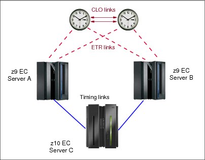
Figure 3-35 Last path validation of coupling links
When the last path condition is raised, any attempt to remove the path from a z/OS image from either end of the link using the z/OS command CONFIG CHP(xx),OFF results in the request being rejected and message IEE148I being issued:
IEE148I CHP(xx) NOT RECONFIGURED - WOULD REMOVE A CPC-CRITICAL STP TIMING LINK
|
Note: Remember also that when a CHPID is configured OFF to an inactive logical partition, the effect is immediate. However, when it is configured ON to an inactive logical partition, the LPAR queues the request and the CHPID is brought online the next time that the logical partition is activated.
|
The Config Off request is also rejected if the FORCE option is specified.
If a last path condition exists on all three servers shown in Figure 3-35, the IEE148I message is issued whether the reconfiguration request is initiated from a z/OS image on server A, on server B, or on server C. If the request is initiated from a z/OS image on server C, message IEE148I is issued for the A–C path, and also for the B–C path.
Message IEE148I is intended as a warning that the action can potentially disrupt the entire CTN and the request is rejected. However, removing the last coupling link between two servers or CFs might be a valid request, for example, for scheduled maintenance or reconfiguration of a server.
When a last path condition exists, the configuration change can only be accomplished from the Hardware Management Console or the Support Element. From the HMC, the first attempt to configure the CHPID Off is rejected with a warning message, but an override option is available. If the override option is selected, the request can be reissued and the CHPID reconfiguration proceeds. However, the decision to override should not be made lightly. The following example illustrates why:
1. Reconfiguration of coupling link B–C is requested, either from server B or server C in Figure 3-35 on page 137.
In this case, the CHPID reconfiguration can be done from the HMC without any damaging consequences to the server C timing. STP messages still flow using the A–C link. However, the resulting configuration, shown in Figure 3-36, now leaves only one coupling link available to server C.
2. If an attempt is made later to configure off the coupling link A–C, whether from server A or server C, the same warning message is issued again.
However, the circumstances are now different. In this situation, if the warning is ignored and the CHPID reconfiguration proceeds, server C loses time synchronization and switches to an unsynchronized state (STP stratum 0). All active z/OS images on server C participating in a Sysplex post WTOR IEA394A. See STP Recovery Guide, SG24-7380, for a description of z/OS message IEA394A. If the server has been assigned a role in the CTN, this could have consequences for the recovery of the entire CTN.
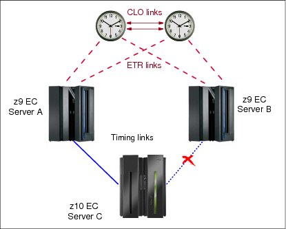
Figure 3-36 Last path validation of coupling links: one remaining link
Over time, the list of channel paths targeted to be configured online or offline to a given logical partition can be changed by system control program configuration commands, configure CHPID On and Off tasks, or dynamic I/O configuration commands. Similarly, reconfigurable unshared channel paths can be moved from one logical partition to another using the same commands, changing the owner of the unshared channel path. Configuration changes are remembered by the Support Element on an IOCDS basis.
To determine whether it is safe to continue with a last path reconfiguration request, the system programmer must assess the consequences to the configuration. The decision requires an understanding of the CTN topology and precise knowledge of what the current timing distribution is at that specific moment in time.
In the STP-only CTN configuration displayed in Figure 3-37, the PCHIDs are indicated so that the reader can relate the STP Status information to the CTN topology. In this example, the coupling link B between server CEC1 and server CEC3 is a potential last timing link. The coupling link A between server CEC3 and server CEC2 is also a potential last timing link.
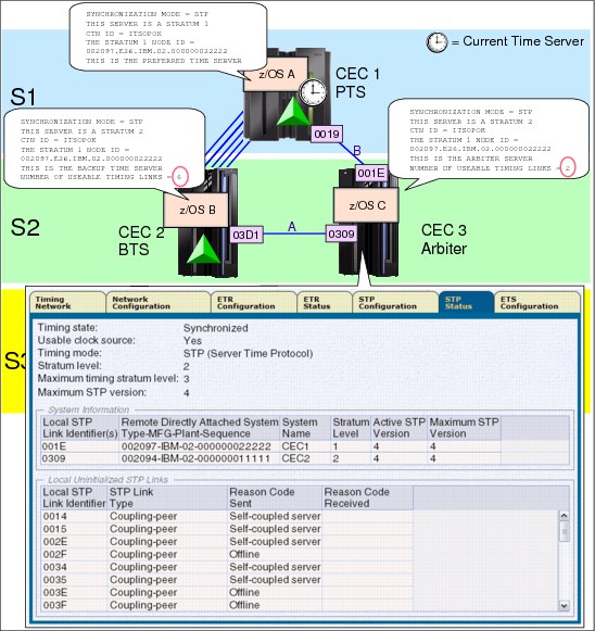
Figure 3-37 Last timing link example
This means that servers, CEC1 and CEC2, each have one potential last timing link. While server CEC3 has two coupling links available for STP messages, each can raise a last timing link condition because each of these links is the last link that is being used to deliver STP timing between two servers.
When a last timing link condition is detected, any attempt to remove the channel path from a z/OS image at either end of the link using the z/OS command CONFIG CHP(xx),OFF is rejected.
In the example shown in Figure 3-38, an attempt to configure a channel path off from a z/OS image on CEC3 results in message IEE148I:
IEE148I CHP(C0) NOT RECONFIGURED - WOULD REMOVE A CPC-CRITICAL STP TIMING LINK
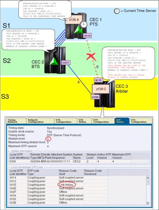
Figure 3-38 Last timing link example: link failure
The Config Off request is also rejected if the FORCE option is specified on the z/OS or CFCC command.
When a last timing link condition exists, the configuration change must be completed on the HMC or Support Element. This procedure is described in detail in the Server Time Protocol Implementation Guide, SG24-7281. Assessing the consequences of forcing a CHPID reconfiguration in a last timing link scenario requires the user to understand the CTN topology at that precise moment in time.
As shown in Figure 3-38 on page 140, there was no hard consequence because STP automatically adjusted to use alternate links. However, CEC3 is now a stratum 3 server and has only one single source and one single link remaining to receive STP messages. The resulting configuration now contains single points of failure.
The primary source of information for operations is z/OS messages. However, z/OS messages provide no information about the last timing link condition because a z/OS system image has no visibility to CHPIDs defined to partitions other than its own.
The output of the z/OS DISPLAY ETR command identifies coupling links (PCHIDs), and only as viewed from the z/OS system image.
•z/OS counts physical links (PCHIDs).
– In the configuration shown in Figure 3-37 on page 139, on CEC3 the DISPLAY ETR output on image LPC identifies no single point of failure:
NUMBER OF USABLE TIMING LINKS = 2
Still, links A and B could raise a last timing link condition if only one online CHPID remains mapped to the PCHID on each server.
– In Figure 3-38 on page 140, on CEC3, the DISPLAY ETR information about image LPC identifies a single point of failure:
NUMBER OF USABLE TIMING LINKS = 1
THIS SERVER HAS ONLY A SINGLE SOURCE OF TIMING SIGNALS
The user must go to the STP Status tabs to map the link to PCHIDs 03D1 to 0309. Again, this does not automatically imply a last timing link condition on CEC3 (or at the other end of the link, on CEC1) because the last timing link condition depends on the contents of the CHPID access list.
•The DISPLAY ETR output provides information only for PCHIDs that are input to the server hosting the z/OS image. It does not consider coupling links to dependent systems. For example, consider the configuration shown in Figure 3-38 on page 140:
– On CEC1, which has the Current Time Server role, the number of usable timing links is not indicated. Since the CTS owns the Current Server Time and does not rely on external links, links are not considered a single point of failure for images on the server.
– On CEC2, the number of usable timing links at this point in time is now five, because z/OS only counts the number of PCHIDs from its host server to the Current Time Server, CEC1.
Notice the difference with the configuration in Figure 3-37 on page 139. Prior to the link failure, the z/OS image running on CEC2 recognized six usable timing links (PCHIDs) because, at the time, CEC3 had connectivity to the Current Time Server and was a possible source of STP timing messages.
•The DISPLAY ETR information is not available for stand-alone coupling facilities since the CFCC has no DISPLAY ETR equivalent.
3.5.5 Disruptive actions on the Current Time Server
A disruptive action on the CTS could jeopardize the entire CTN. Protection has been added to prevent a disruptive task from being performed on a server that:
•Is configured as the Current Time Server
•Has initialized STP links to stratum 2 servers
When these conditions are met, the server is locked for disruptive tasks such as activate, deactivate, power off, power-on reset, disruptive switch to alternate SE, and so on.
The user is also prevented from modifying the server STP ID and ETR Network ID on the STP Configuration tab, and modification of the ETR Network ID on the ETR Configuration tab.
For example, as illustrated in Figure 3-39, server SCPZ201 satisfies the two conditions. SCPZ201 is stratum 1 in the CTN and is the time source for other servers in the CTN.
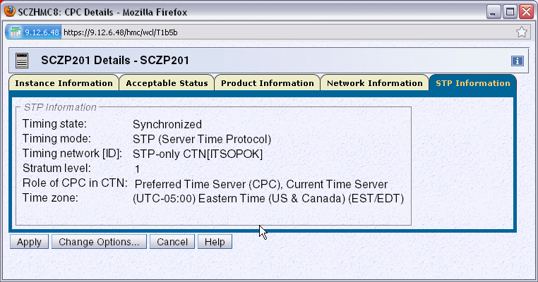
Figure 3-39 CPC Details: STP Information tab
The STP Status tab (Figure 3-40) shows that SCZP201 has initialized STP links to SCZP101, another server in the same CTN.
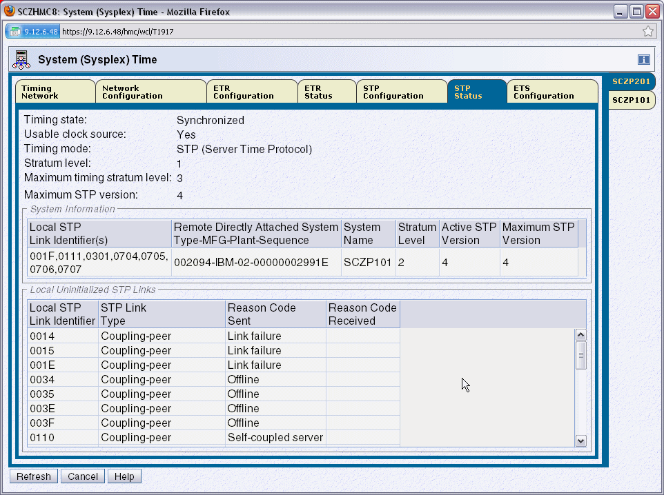
Figure 3-40 STP Status tab
Special checking is only done for the Current Time Server in an STP-only CTN. Only the combination of CTS role and active STP link conditions is checked. The disruptive-action detection does not check for other server roles in the CTN.
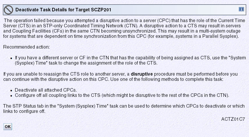
Figure 3-41 Deactivate Task details: message ACTZ01C7
No alternative action is possible from this panel. The user can only acknowledge that the request has failed and click OK.
If the request really must be pursued, the solution is to first change the STP configuration by reconfiguring the Current Time Server to another server from the Network Configuration page of the server that will become the new CTS. Only then can the deactivate request be accepted.
If the CTS cannot be re-assigned, the alternatives will be disruptive to maintaining synchronization for other servers in the CTN. The alternatives are to deactivate all the stratum 2 and stratum 3 servers in the CTN first. Once that is done the disruptive action on the CTS can be performed.
Configure off all the coupling link CHPIDs from the CTS to all its attached servers. The special procedure that must be used to configure off all, or more precisely the last CHPID used for STP timing is described in the following section. The disruptive action on the CTS can be performed after this action is completed.
3.5.6 Disruptive actions on the BTS or Arbiter
Disruptive actions are now blocked for the BTS and Arbiter. This new function was introduced with the MCL levels shown in Table 3-10.
Table 3-10 Blocked disruptive actions
|
Driver/Server
|
MCL
|
Bundle
|
Release Date
|
|
D86E / z196
|
N29809.277
|
45
|
Sept 8, 2011
|
|
D86E / z196
|
N29802.420
|
45
|
Sept 8, 2011
|
|
D79F / z10
|
N24415.078
|
50
|
Sept 28, 2011
|
|
D79F / z10
|
N24409.184
|
50
|
Sept 28, 2011
|
|
D93G / z114 and z196 GA2
|
Integrated
|
N/A
|
Sept 9, 2011
|
This provides the same safeguards for the BTS and Arbiter as described in 3.5.5, “Disruptive actions on the Current Time Server” on page 142. This prevents a disruptive action causing the CTS to give up the S1 role and go S0. For example, if the PTS has the CTS role and then the Arbiter (or BTS) has a planned or unplanned outage, a disruptive action on the BTS (or Arbiter) causes the CTS to give up the S1 role and go S0 as it loses communication to both the BTS and Arbiter.
|
Attention: This recent restriction that a disruptive action cannot be taken against the server assigned with the BTS role has changed how the “Only allow the server(s) specified above to be in the CTN” button is used because it requires that a BTS is assigned in a two server CTN. This means that the BTS server has to be removed from the CTN when the BTS role is removed to allow the “Only allow the server(s) specified above to be in the CTN” button to be selected when the PTS is PORed.
|
3.5.7 Restarting a CTN power outage or power-on reset (unplanned)
A fundamental aspect of an STP-only CTN is that the network design must make sure that it does not create an island condition, where two active stratum 1 servers exist within the same CTN. This is because a stratum 1 server does not synchronize to any other servers’ time in the CTN, but is the one with which all other servers are synchronized. If two stratum 1 servers were allowed to exist in the same CTN, the software and applications running on them would consider the two stratum 1 servers to be synchronized, when in fact they most likely are not.
After a power outage is restored, when an individual server is powered up, it does not know whether the entire data center has been shut down, whether there has been a physical or logical reconfiguration during the shutdown, or whether the customer might not want to re-instate the same roles to the servers that existed prior to the power outage. Therefore, in order to make sure that an island condition is not inadvertently created after a power outage, the STP design:
•Deconfigures the CTN if the power outage has affected both the PTS and the BTS. This results in all servers in the CTN becoming unsynchronized stratum 0 servers.
•Requires an STP-configured server that is being powered-on to obtain its configuration information from the CTN that is already up and running, if one exists, rather than making an independent decision about its role in the CTN. So, if the power outage affects only one time server (PTS or BTS) and recovery actions have permitted the CTN to stay operational, the affected server can rejoin the CTN without requiring a restart of the CTN.
The server roles therefore must be reassigned after:
•The CTS in a single-server CTN has been power-on reset or has gone through a power-off/on sequence and has not been specified to be the only member of the CTN.
•The PTS (and the BTS if assigned) in a two-server CTN has been power-on reset or has gone through a power-off/on sequence and has not been specified to be the only members of the CTN.
•The PTS (and the BTS if assigned) in a three or more server CTN experience a power outage (for example, a data center power outage).
•An STP-only CTN is deconfigured intentionally by the user.
When the site power is restored or after an STP-only CTN is deconfigured, the CTN remains deconfigured, all participating servers being stratum 0.
The Network Configuration tab shows that the PTS, BTS, and Arbiter are not configured, as shown in Figure 3-42. Servers rely on explicit instructions from the console to re-establish a new time source and reconfigure the CTN.

Figure 3-42 HMC workplace: System (Sysplex) Time, Network Configuration
This is a change from the restart procedures used in a similar situation when using a Sysplex Timer configuration. Operating procedures should be modified accordingly. The sequence to restart an STP-only CTN is:
1. Set the time zone offset, leap seconds, and date and time.
2. Assign the CTN roles.
Set the time zone offset, leap seconds, and date and time
The three tasks related to setting the time are:
•Set leap seconds.
•Set time zone.
•Set date and time.
This is accomplished by clicking Initialize Time on the Network Configuration tab, shown in Figure 3-42. The button becomes enabled when the CTN has been deconfigured as a result of a site power failure or POR of a single server CTN.
Following a power outage or POR of the CTS, the date and time can be set depending on the following:
•If the ETS is configured and is already available at the time of the recovery, the preferred method is to use the Use External Time Source option.
•For those customers who do not have an ETS, select Modify time by delta to set date and time and enter a delta value of zero.
Assign the CTN roles
Once the initialize time task has been completed, the Apply button on the Network Configuration tab becomes enabled and server roles can be assigned. Under normal circumstances, we recommend performing the configuration in two distinct steps. However, following a site power outage, it might be convenient to force the configuration in one step, because not all servers might be in POR-complete state.
The roles are assigned from the Network Configuration tab from the server that will become the Current Time Server.
1. Assign the PTS role, the BTS if there are two or more servers, and the Arbiter if the CTN has three or more participating servers.
For each of the roles (PTS, BTS, and Arbiter) there are drop-down boxes listing the servers currently available. Only STP-enabled servers with their Support Element visible to the HMC are selectable. In a normal situation, when the HMC has connectivity to the server, the STP ID information is shown if there is an initialized STP link to the target server and the server participates to the same CTN. In a recovery situation, a server’s Support Element might be visible to the HMC, but the STP ID is not available. This means that either the activation of this particular server is not complete or coupling link connectivity has not yet been re-established.
2. Assign the CTS role.
3. Click the Force configuration check box. The option bypasses a number of validity checks on server connectivity, allowing the configuration of servers that might not be in POR-complete state or do not yet have coupling link connectivity to the selected CTS.
4. Click Apply. The assignment of the CTS globally configures into the CTN all servers that:
– Are already powered-on and in POR-complete state
– Have the same CTN ID as the CTS
– Have coupling link connectivity to the CTS
Other servers that are not yet in POR-complete state, or that have not yet re-established connectivity to the CTS, automatically join the CTN and recognize their role assignments once their operating conditions return to normal.
After all conditions have returned to normal, we recommend that the server roles be reconfigured to the configuration that was in place before the outage.
3.5.8 Planned single-site maintenance
This section presents an alternate way to shut down/power on the CECs in a single site configuration when site power or building maintenance is scheduled.
The automatic activation of CECs is allowed using the proper sequence:
1. When initiating the maintenance:
a. Deactivate every CEC but the PTS/CTS.
b. Remove the BTS and Arbiter roles
c. On the PTS/CTS, remove the Arbiter role, then click the Only allow the server(s) specified above to be in the CTN box to keep the configuration at next power on.
d. Deactivate the PTS/CTS (which is now not synchronizing with any other CEC, so the deactivate is not blocked).
2. After the maintenance, take the following steps.
|
Note: After a power off/on sequence, the TOD value in the CTS is initialized from the TOD values stored in its SE. If you previously configured an ETS, STP code does not perform an initialize time using the ETS, but automatically accesses the configured ETS and starts adjusting the time so as to maintain time accuracy. STP allows time adjustments of up to +/- 60 seconds.
|
a. Activate the PTS/CTS first. It becomes stratum 1 (CTN configuration kept).
b. From the PTS/CTS, deselect the Only allow the server(s) specified above to be in the CTN option.
c. Activate the other CECs. They become stratum 2 or stratum 3, as appropriate, during their automatic activation.
d. From the PTS/CTS, reassign the BTS and Arbiter roles.
This speeds up the reactivation of the CECs and simplifies the customer procedures for this scenario.
See also Server Time Protocol Implementation Guide, SG24-7281.
3.6 MES upgrade considerations
If you are upgrading a machine with a different footprint (often referred to as a push/pull MES) the machine type and possibly the serial number change. A server is deactivated, powered off, uncabled, and then moved aside for the new server to take its place. In other cases the new server is powered up alongside the one that it is replacing and is configured for a workload migration.
Configuring a new server might include IPLing a stand-alone image in order to load Crypto keys. As mentioned in 1.5.2, “Coupling link requirements in a non-sysplex configuration” on page 23, if this new server will be accessing any primary volumes that are part of an XRC relationship, your new server must observe the same time reference used by existing servers using those volumes. This can be accomplished by either joining the new server to the same CTN ID as the other servers or creating a new CTN but using the same ETS to initialize the time.
Depending on your current CTN configuration you might need to plan for certain actions prior to the MES. The issues discussed are categorized between:
•Mixed CTN
•STP-only CTN
3.6.1 Mixed CTN
If CEC1 is being replaced (Figure 3-43), since the recommendation is to always have two STP timing sources for any stratum 2 servers, CEC2’s ETR ports (if still cabled to enabled ports on the Sysplex Timers) should be enabled to make it a stratum 1 server. Ensure beforehand that CEC2 has initialized STP links to the other stratum 2 servers.
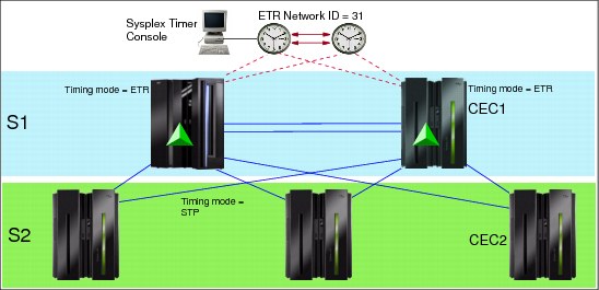
Figure 3-43 Replacing CEC1 in a Mixed CTN
If a new server will be temporarily joining the CTN you must plan for timing links for the new server. If either of the stratum 1 servers have unused CFP CHPIDs currently defined to and online to at least one CF LPAR, those links can be used as a timing source. If there are none you might have to dynamically define timing or timing-only links from one of the other servers.
3.6.2 STP-only CTN
If your STP-only CTN consists of one or two servers and you are only allowing these servers to be in the CTN per the option on the Network Configuration tab (see “Activating the STP-only CTN” on page 104, regarding this option), ensure that this option is deselected before powering off the server being replaced. Otherwise, the new server’s node ID will not be recognized and will not be allowed to join the existing CTN.
When replacing the PTS/CTS in a multi-server CTN, always move the PTS/CTS role to a server that is not being replaced. Similarly, if the BTS is being replaced, assign another server in the CTN as a BTS so that recovery for a loss of the CTS is possible. Refer to section 3.4 of the Server Time Protocol Implementation Guide, SG24-7281, for more information.
Also in a multi-server CTN, using your CTN topology diagram, ensure that the server being replaced does not leave you with a last timing link condition upon deactivation. To illustrate, in Figure 3-44 we swap out CEC2 from a z9 to a z10.
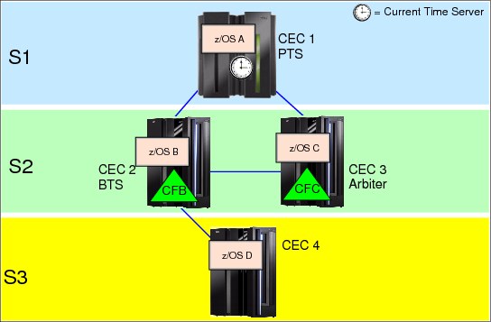
Figure 3-44 Replacing CEC2 from a z9 to a z10
After completion of structure rebuilds from CFB to CFC and moving the workload off of z/OS B, there are no operational safeguards to prevent you from deactivating CEC2 if a last timing link condition exists. This would be the case if CEC3 was not part of the CTN or did not provide alternate STP timing connectivity to CEC4 (see Example 3-28).
Example 3-28 Messages revealing single points of failure for CEC4
CNZHF0005I One or more consoles are configured to receive messages
intended only for programmers.
15.18.09 SC81 STC03801 HZS0002E CHECK(IBMXCF,XCF_CF_PROCESSORS):
IXCH0444E Coupling facility processor configurations in use by the
local system may result in degraded response time and throughput
for coupling facility requests.
15.18.09 SC81 STC03801 HZS0001I CHECK(IBMCATALOG,
CATALOG_IMBED_REPLICATE):
IGGHC104E The CATALOG_IMBED_REPLICATE check has detected one or
more catalogs defined with the IMBED and/or REPLICATE attributes.
15.18.09 SC81 STC03801 HZS0001I CHECK(IBMCSV,CSV_LNKLST_SPACE):
CSVH0980E Some LNKLST sets include data set(s) allocated with
secondary space defined.
*15.18.10 SC81 STC03801 *HZS0003E CHECK(IBMXCF,XCF_CDS_SPOF):
*IXCH0242E One or more couple data sets have a single point of failure.
15.18.22 SC81 STC03801 HZS0001I CHECK(IBMCSV,CSV_APF_EXISTS):
CSVH0957E Problem(s) were found with data sets in the APF list.
15.18.26 SC81 STC03801 HZS0001I CHECK(IBMUSS,USS_PARMLIB):
BPXH046E Syntax error(s) were found in the parmlib members.
*15.18.27 SC81 STC03801 *HZS0003E CHECK(IBMRACF,RACF_SENSITIVE_RESOURCES):
*IRRH204E The RACF_SENSITIVE_RESOURCES check has found one or
*more potential errors in the security controls on this system.
15.42.59 SC80 ICH408I USER(HAIMO ) GROUP(SYS1 ) NAME(HAIMO 
1 This panel is for GLOBAL changes (affecting all servers in the CTN).
2 This panel is for LOCAL changes (affecting only the selected server).
3 In earlier server documentation this function was called logical partition Sysplex Timer offset.
..................Content has been hidden....................
You can't read the all page of ebook, please click here login for view all page.
