Advanced Encryption Standard
Introduction
The Advanced Encryption Standard (AES) began in 1997 with an announcement from NIST seeking a replacement for the aging and insecure Data Encryption Standard (DES). At that point, DES has been repeatedly shown to be insecure, and to inspire confidence in the new standard they asked the public to once again submit new designs. DES used a 56-bit secret key, which meant that brute force search was possible and practical. Along with a larger key space, AES had to be a 128-bit block cipher; that is, process 128-bit blocks of plaintext input at a time. AES also had to support 128-, 192-, and 256-bit key settings and be more efficient than DES.
Today it may seem rather redundant to force these limitations on a block cipher. We take AES for granted in almost every cryptographic situation. However, in the 1990s, most block ciphers such as IDEA and Blowfish were still 64-bit block ciphers. Even though they supported larger keys than DES, NIST was forward looking toward designs that had to be efficient and practical in the future.
As a result of the call, 15 designs were submitted, of which only five (MARS, Twofish, RC6, Serpent, and Rijndael) made it to the second round of voting. The other 10 were rejected for security or efficiency reasons. In late 2000, NIST announced that the Rijndael block cipher would be chosen for the AES. The decision was based in part on the third-round voting where Rijndael received the most votes (by a fair margin) and the endorsement of the NSA. Technically, the NSA stated that all five candidates would be secure choices as AES, not just Rijndael.
Rijndael is the design of two Belgian cryptographers Joan Daemen and Vincent Rijmen. It was actually a revisit of the Square block cipher and re-designed to address known attacks. It was particularly attractive during the AES process because of its efficiencies (it is one of the most commonly efficient designs) and the nice cryptographic properties. Rijndael is a substitution-permutation network that follows the work of Daemens Ph.D. wide-trail design philosophy. It was proven to resist both linear and differential cryptanalysis (attacks that broke DES) and has very good statistical properties in other regards. In fact, Rijndael was the only one of the five finalists to be able to prove such claims. The other security favorite, Serpent, was conjectured to also resist the same attacks but was less favored because it is much slower.
Rijndael (or simply AES now) is patent free, and the creators have given out various reference implementations as public domain. Their fast implementation is actually the basis of most software AES implementations, including those of OpenSSL, GnuPG, and LibTomCrypt. The fast and semi-fast implementations in this text are based off the Rijndael reference code.
Block Ciphers
Before we go ahead into the design of AES, we should discuss what block ciphers are and the role they fill in cryptography.
The term block cipher actually arose to distinguish said algorithms from the normal stream ciphers that were commonplace. A cipher is simply a process to conceal the meaning of a message. Originally, these were in the form of simple substitution ciphers followed by stream ciphers, which would encode individual symbols of a message. In terms of practical use, this usually involved rotors and later shift registers (like LFSRs). The theory seemed to be to find a well-balanced generator of a provably long period, and filter the output through a nonlinear function to create a keystream. Unfortunately, many relatively recent discoveries have made most LFSR-based ciphers insecure.
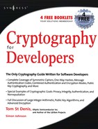
A block cipher differs from a stream cipher in that it encodes a grouping of symbols in one step. The mapping from plaintext to ciphertext is fixed for a given secret key. That is, with the same secret key the same plaintext will map to the same ciphertext. Most commonly used block ciphers have block sizes of either 64 or 128 bits. This means that they process the plaintext in blocks of 64 or 128 bits. Longer messages are encoded by invoking the cipher multiple times, often with a chaining mode such as CTR to guarantee the privacy of the message. Due to the size of the mapping, block ciphers are implemented as algorithms as opposed to as a large lookup table (Figure 4.1).
Early block ciphers include those of the IBM design team (DES and Lucifer) and eventually a plethora of designs in the 1980s and early 1990s. After AES started in 1997, design submissions to conferences drastically died off. The early series of block ciphers encoded 64-bit blocks and had short keys usually around 64 bits in length. A few designs such as IDEA and Blowfish broke the model and used much larger keys. The basic design of most ciphers was fairly consistent: find a somewhat nonlinear function and iterate it enough times over the plaintext to make the mapping from the ciphertext back to plaintext difficult without the key. For comparison, DES has 16 rounds of the same function, IDEA had 8 rounds, RC5 originally had 12 rounds, Blowfish had 16 rounds, and AES had 10 rounds in their respective designs, to name a few ciphers. (The current consensus is that RC5 is only secure with 16 rounds or more. While you should usually default to using AES, RC5 can be handy where code space is a concern.) By using an algorithm to perform the mapping, the cipher could be very compact, efficient, and used almost anywhere.
Technically speaking, a block cipher is what cryptographers call a Pseudo Random Permutation (PRP). That is, if you ran every possible input through the cipher, you would get as the output a random permutation of the inputs (a consequence of the cipher being a bijection). The secret key controls the order of the permutation, and different keys should choose seemingly random looking permutations.
Loosely speaking, a “good” cipher from a security point of view is one where knowing the permutation (or part of it) does not reveal the key other than by brute force search; that is, an attacker who gathers information about the order of the permutation does not learn the key any faster than trying all possible keys. Currently, this is believed to be the case for AES for all three supported key sizes.
Despite the fact that a block cipher behaves much like a random permutation, it should never be used on its own. Since the mapping is static for a given key the same plaintext block will map to the same ciphertext block. This means that a block cipher used to encrypted data directly leaks considerable data in certain circumstances.
Fortunately, it turns out since we assume the cipher is a decent PRP we can construct various things with it. First, we can construct chaining modes such as CBC and CTR (discussed later), which allow us to obtain privacy without revealing the nature of the plaintext. We can also construct hybrid encrypt and message authentication codes such as CCM and GCM (see Chapter 7, “Encrypt and Authenticate Modes”) to obtain privacy and authenticity simultaneously. Finally, we can also construct PRNGs such as Yarrow and Fortuna.
Block ciphers are particularly versatile, which makes them attractive for various problems. As we shall see in Chapter 5, “Hash Functions,” hashes are equally versatile, and knowing when to tradeoff between the two is dependent on the problem at hand.
AES Design
The AES (Rijndael) block cipher (see http://csrc.nist.gov/publications/fips/fipsl97/fips-197.pdf) accepts a 128-bit plaintext, and produces a 128-bit ciphertext under the control of a 128-, 192-, or 256-bit secret key. It is a Substitution-Permutation Network design with a single collection of steps called a round that are repeated 9, 11, or 13 times (depending on the key length) to map the plaintext to ciphertext.
A single round of AES consists of four steps:
Each round uses its own 128-bit round key, which is derived from the supplied secret key through a process known as a key schedule. Do not underestimate the importance of a properly designed key schedule. It distributes the entropy of the key across each of the round keys. If that entropy is not spread properly, it causes all kinds of trouble such as equivalent keys, related keys, and other similar distinguishing attacks.
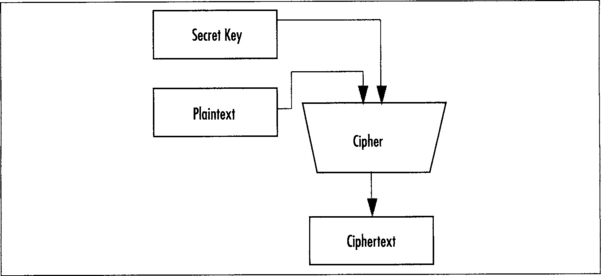
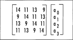
AES treats the 128-bit input as a vector of 16 bytes organized in a column major (big endian) 4x4 matrix called the state. That is, the first byte maps to a0,0, the third byte to a3,0, the fourth byte to a0,1, and the 16th byte maps to a3,3 (Figure 4.2).
The entire forward AES cipher then consists of
Finite Field Math
The AES cipher can actually be fully specified as a series of scalar and vector operations on elements of the field GF(2). It is not strictly important to master totally the subject of Galois fields to understand AES; however, a brief understanding does help tweak implementations. Do not fret if you do not understand the material of this section on the first read. For the most part, unless you are really optimizing AES (especially for hardware), you do not have to understand this section to implement AES efficiently.
GF(p) means a finite field of characteristic p. What does that mean? First, a quick tour of algebraic groups. We will cover this in more detail in the discussion of GCM and public key algorithms. A group is a collection of elements (elements can be numbers, polynomials, points on a curve, or anything else you could possibly place into an order with a group operator) with at least one well-defined group operation that has an identity, a zero, and an inverse.
A ring is a group for which addition is the group operation; note that this does not strictly mean integer addition. An example of a ring is the ring of integers denoted as Z. This group contains all the negative and positive whole numbers. We can create a finite ring by taking the integers modulo an integer, the classic example of which is clock arithmetic—that is, the integers modulo 12. In this group, we have 12 elements that are the integers 0 through 11. There is an identity, 0, which also happens to be the zero. Each element a has an inverse—a. As we shall see with elliptic curve cryptography, addition of two points on a curve can be a group operation.
A field is a ring for which there also exists a multiplication operator. The field elements of a group are traditionally called units. An example of a field would be the field of rational numbers (numbers of the form a/b). A finite field can be created, for example, by taking the integers modulo a prime. For example, in the integers modulo 5 we have five elements (0 through 4) and four units (1 through 4). Each element follows the rules for a finite ring. Additionally, every unit follows the rules for a finite field. There exists a multiplicative identity, namely the element 1. Each unit a has a multiplicative inverse defined by 1/a modulo 5. For instance, the inverse of 2 modulo 5 is 3, since 2*3 modulo 5 = 1.
Consicely, this means we have a group of elements that we can add, subtract, multiply, and divide. Characteristic p means a field of p elements (p–1 units since zero is not a unit) modulo the prime p. GF(p) is only defined when p is prime, but can be extended to extension fields denoted as GF(pk). Extension fields are typically implemented in some form of polynomials basis; that is to say, an element of GF(pk) is a polynomial of degree k–1 with coefficients from GF(p).
AES uses the field GF(2), which effectively is the field of integers modulo 2. However, it extends it to the field of polynomials, usually denoted as GF(28), and at times treats it as a vector, denoted as GF(2)8. As the smallest unit, AES deals with 8-bit quantities, which is often written as GF(28). This is technically incorrect, as it should be written as GF(2)[x] or GF(2)8. This representation indicates a vector of eight GF(2) elements, or simply, eight bits.
Things get a bit messy for the newcomer with the polynomial representation denoted by GF(2)[x]. This is the set of polynomials in x with coefficients from GF(2). This representation means that we treat the vector of eight bits as coefficients to a seventh degree polynomial (e.g., <a0,a1,a2,a3,a4,a5,a6,a7> turns into the polynomial p(x) = a0x0 + a1x1 + … + a7x7).
To create a field, we have to use a polynomial that is not divisible by any lower degree polynomial from the same basis (GF(2)). Typically, such polynomials are known as irreducible polynomials. We define the entire field as GF(2)[x]/v(x), where v(x) is the irreducible polynomial. In the case of AES, the polynomial v(x) = x8 + x4 + x3 + x + 1 was chosen. When the bits of v(x) are stored as an integer, it represents the value 0x11B. The curious reader may have also heard of the term primitive polynomial, which means that the polynomial g(x) = x would generate all units in the field. By generate, we mean that there is some value of k such that g(x)k = y(x) for all y(x) in GF(2)[x]/v(x). In the case of AES, the polynomial v(x) is not primitive, but the polynomial g(x) = x + 1 is a generator of the field.
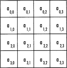
Addition in this field is a simple XOR operation. If both inputs are of degree 7 or less, no reduction is required. Otherwise, the result must be reduced modulo v(x). Multiplication is just like multiplying any other polynomial. If we want to find c(x) = a(x)b(x), we simply find the vector <c0, c1, c2, …, c15>, where cn is equal to the sum of all the products for that coefficient. In C, the multiplication is
This algorithm is a trivial double-and-add algorithm (analogous to square-and-multiply as we shall see with RSA), which computes the product ab in the field that AES uses. In the loop, we first test if the least significant bit of a is set. If so, we add the value of b to res. Next, we multiply b by x with a shift. If a vector of bits represents the polynomial, then inserting a zero bit on the right is equivalent. Next, we reduce b modulo the AES polynomial. Essentially, if the eighth bit is set, we subtract (or XOR) the modulus from the value.
This polynomial field will be used both in the SubBytes and MixColumn stages. In practice, at least in software, we do not implement the multiplication this way, as it would be too slow.
AddRoundKey
This step of the round function adds (in GF(2)) the round key to the state. It performs 16 parallel additions of key material to state material. The addition is performed with the XOR operation (Figure 4.3).

The k matrix is a round key and there is a unique key for each round. Since the key addition is a simple XOR, it is often implemented as a 32-bit XOR across rows in 32-bit software.
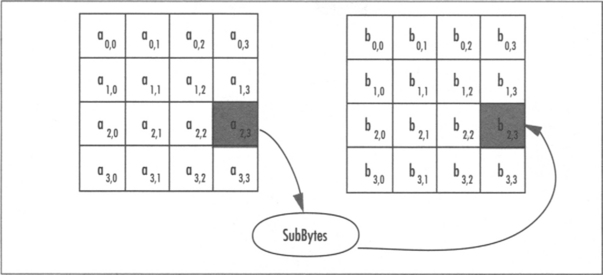
SubBytes
The SubBytes step of the round function performs the nonlinear confusion step of the SPN. It maps each of the 16 bytes in parallel to a new byte by performing a two-step substitution (Figure 4.4).
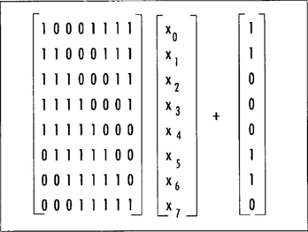
The substitution is composed of a multiplicative inversion in GF(2)[x]/v(x) followed by an affine transformation (Figure 4.5) in GF(2)8. The multiplicative inverse of a unit a is another unit b, such that ab modulo the AES polynomial is congruent (equivalent to, or equal to when reduced by v(x)) to the polynomial p(x) = 1. For AES, we make the exception that the inverse of a(x) = 0 is itself.
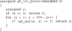
There are several ways to find the inverse. Since the field is small, brute force requiring on average 128 multiplications can find it. With this approach we simply multiply a by all units in the field until the product is one.
It can also be found using the power rules. The order of the field GF(28) is 28 – 1 = 255 and a(x)254 = a(x)−1. Computing a(x)254 can be accomplished with eight squarings and seven multiplications. We list them separately, since squaring in GF(2) is a O(n) time operation (as opposed to the O(n2) that multiplication requires).
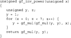
Here we used gf_mul to perform the squarings. However, there are faster and more hardware friendly ways of accomplishing this task. In GF(2)[x] the squaring operation is a simple bit shuffle by inserting zero bits between the input bits. For example, the value 11012 becomes 101000102. After the squaring, a reduction would be required. In software, for AES at least, the code space used to perform the function would be almost as large as the SubBytes function itself. In hardware, squaring comes up in another implementation trick we shall discuss shortly.
It can also be found by the Euclidean algorithm and finally by using log and anti-log (logarithm) tables. For software implementations, this is all overkill. Either the SubBytes step will be rolled into ShiftRows and MixColumns (as we will discuss shortly), or is implemented entirely as a single 8x8 lookup table.
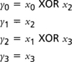
After the inversion, the eight bits are sent through the affine transformation and the output is the result of the SubBytes function. The affine transform is denoted as
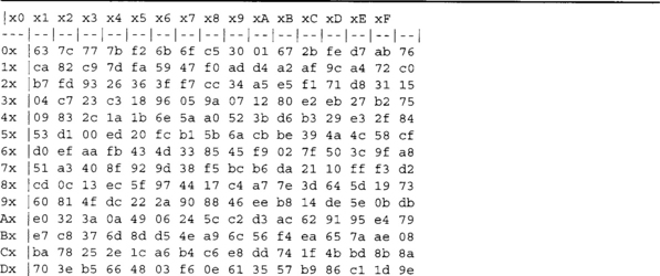
Where the vector <x0, x1, x2, …, x7> denotes the eight bits from least to most significant. Combined, the SubByte substitution table for eight bit values is as shown if Figure 4.6.
The inverse of SubBytes is the inverse of the affine transform followed by the multiplicative inverse. It can be easily derived from the SubBytes table with a short loop.
![]()
Hardware Friendly SubBytes
This section discusses a trick for hardware implementations1 that is not useful for software (information thanks to Elliptic Semiconductor—www.ellipticsemi.com). We include it here since the information is not that widespread and tends to be very handy if you are in the hardware market.
The hardware friendly SubBytes implementation takes advantage of the fact that you can compute the multiplicative inverse by computing a much smaller inverse and then applying some trivial GF(2) math to the output. This allows the circuit to be smaller and in most cases faster than an 8x8 ROM table implementation.
The general flow of this algorithm is the following.
1. Apply a forward linear mapping to the 8-bit input.
2. Split the 8-bit result into two 4-bit words b and c (b being the most significant nibble).
3. Compute d = ((b2 * r(x)) XOR (c*b) XOR c2)−1.
6. Apply the inverse linear mapping to the 8-bit word p | | q.
Where the multiplications are GF(2)[x]/t(x) multiplications modulo t(x) = x4 + x1 + 1, the value of r(x) is x3 + x2 + x, and the modular inversion (step 3) is a 4-bit inversion modulo t(x). The forward linear mapping is defined as the following 8x8 matrix (over GF(2)).

The inverse linear mapping is the inverse matrix transform over GF(2). The inverse mapping follows.

This trick takes advantage of the fact that squaring is virtually a free operation. If the input to the squaring is the vector <x0,x1,x2,x3> (x0 being the least significant bit), then these four equations can specify the output vector.
The output vector <y0, y1, y2, y3> is the square of the input vector modulo the polynomial t(x). You can implement the 4-bit multiplications in parallel since they are very small. The multiplication by r(x) is constant so it does not have to be implemented as a full GF(2)[x] multiplier. The 4-bit inversion can either be performed by a ROM lookup, decomposed (using this trick recursively), or let the synthesizer attempt to optimize it.
After applying the six-step algorithm to the 8-bit input, we now have the modular inverse. Applying the AES affine transformation completes the SubBytes transformation.
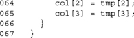
ShiftRows
The ShiftRows step cyclically shifts each row of the state to the left by 0, 1, 2, and 3 positions (respectively). It’s entirely linear (Figure 4.7).
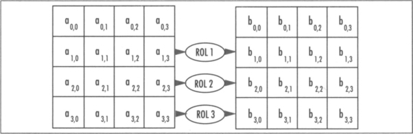
In practice, we will see this is implemented through renaming rather than an actual shift. That is, instead of moving the bytes around, we simply change from where we fetch them. In 32-bit software, we can combine shift rows fairly easily with SubBytes and MixColumns without having to swap bytes around.
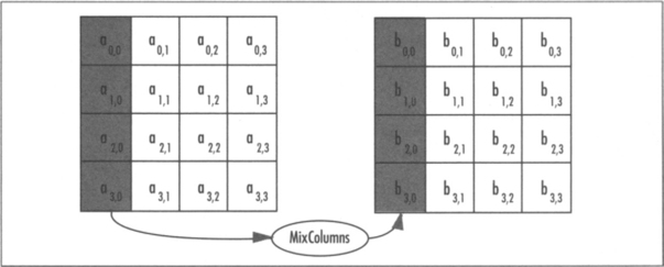
MixColumns
The MixColumns step multiplies each column of the state by a 4x4 transform known as a Maximally Distance Separable (MDS). The purpose of this step is to spread differences and make the outputs linearly dependant upon other inputs. That is, if a single input byte changes (and all other input bytes remain the same) between two plaintexts, the change will spread to other bytes of the state as fast as possible (Figure 4.8).
In the case of AES, they chose an MDS matrix to perform this task. The MDS transforms actually form part of coding theory responsible for things such as error correction codes (Reed-Solomon). They have a unique property that between two different k-space inputs the sum of differing input and output co-ordinates is always at least k+1. For example, if we flip a bit of one of the input bytes between two four-byte inputs, we would expect the output to differ by at least (4+1)–1 bytes.
MDS codes are particularly attractive for cipher construction, as they are often very efficient and have nice cryptographic properties. Currently, several popular ciphers make use of MDS transforms, such as Square, Rijndael, Twofish, Anubis and Kazhad (the latter two are part of the NESSIE standardization project).
The SubBytes function provides the nonlinear component of the cipher, but it only operates on the bytes of the state in parallel. They have no affect on one another. If AES had MixColumns removed, the cipher would be trivial to break and totally useless.
The MDS matrix is generated by the vector <2,3,1,1>, which is expressed in Figure 4.9.
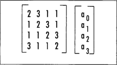
The multiplications involved are performed in the field GF(2)[x]/v(x), which is where the SubBytes step is performed. The actual values of 1, 2, and 3 map directly to polynomials. For instance, 2 = x and 3 = x + 1.
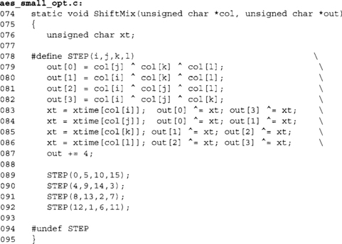
The MixColumns step can be implemented in various manners depending on the target platform. The simplest implementation involves a function that performs a multiplication by x, traditionally called xtime.

The function accesses data offset by four bytes, which corresponds to the width of the AES state matrix. The function would be called four times with col offset by one byte each time. In practice, the state would be placed in alternating buffers to avoid the double buffering required (copying from tmp[] to col[], for instance). In typical hardware implementations, this direct approach is often the method chosen, as it can be implemented in parallel and has a short critical path.
There is another way to implement MixColumn in software that actually allows us to combine SubBytes, ShiftRows, and MixColumns into a single set of operations. First, consider the round function without ShiftRows or SubBytes.
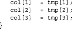
The MixColumn function is a 32x32 linear function, which can be implemented with four 8x32 lookup tables. We create four 8x32 tables where each byte of the output (for all 256 words) represents the product of MixColumn if the other three input bytes were zero. The following code would generate the table for us using the MixColumn() function.
Now, if we map mc_tab to an array of 4*256 32-bit words by loading each four-byte vector in little endian format, we can compute MixColumn as
Note that we now assume mc_tab is an array of 32-bit words. This works because matrix algebra is commutative. Assume the MixColumns transform is the matrix C, and we have an input vector of <a,b,c,d>; what this optimization is saying is we can compute the product C<a,b,c,d> as C<a,0,0,0> + C<0,b,0,0> + … + C<0,0,0,d>. Effectively, mc_tab[0][a] is equivalent to [2, 1, 1, 3]*a for all 256 values of a. Since each component of the vector is only an eight-bit variable, we can simply use a table lookup. That is, we pre-compute C<a,0,0,0> for all possible values of a (and call this mc_tab[0]). We then do the same for C<0,b,0,0>, C<0,0,c,0>, and C<0,0,0,d>. This approach requires one kilobyte of storage per table, and a total of four kilobytes to hold the four tables.
There is tradeoff in this approach. Due to the nature of the matrix, the words in mc_tab[l] are actually equal to the words in mc_tab[0] cyclically rotated by eight bits to the right. Similarly, the words in mc_tab[2] are rotated 16 bits, and mc_tab[3] are rotated 24 bits. This allows us to compress the table space to one kilobyte by trading time for memory. (This also will help against certain forms of timing attacks as discussed later.)
The inverse of MixColumns is the transform shown in Figure 4.10.
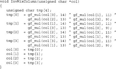
As we can see, the forward transform has simpler coefficients (fewer bits set), which comes into play when choosing how to use AES in the field. The inverse transform can also be implemented with tables, and the same compression trick can also be applied to the implementation. In total, only two kilobytes of tables are required to implement the compressed approach. On eight-bit platforms, the calls to gf_mul() can be replaced with table lookups. In total, one kilobyte of memory would be required.
Last Round
The last round of AES (round 10, 12, or 14 depending on key size) differs from the other rounds in that it applies the following steps:
Inverse Cipher
The inverse cipher is composed of the steps in essentially the same order, except we replace the individual steps with their inverses.
In theses steps, the “Inv” prefix means the inverse operation. The key schedule is slightly different depending on the implementation. We shall see that in the fast AES code, moving AddRoundKey to the last step of the round allows us to create a decryption routine similar to the encryption routine.
Key Schedule
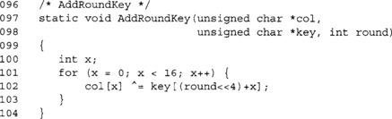
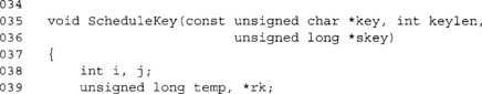
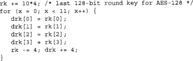
The key schedule is responsible for turning the input key into the Nr+1 required 128-bit round keys. The algorithm in Figure 4.11 will compute the round keys.
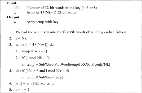
The key schedule requires two additional functions. SubWord() takes the 32-bit input and sends each byte through the AES SubBytes substitution table in parallel. RotWord() rotates the word to the right cyclically by eight bits. The Rcon table is an array of the first 10 powers of the polynomial g(x) = x modulo the AES polynomial stored only in the most significant byte of the 32-bit words.
Implementation
There are already many public implementations of AES for a variety of platforms. From the most common reference, implementations are used on 32-bit and 64-bit desktops to tiny 8-bit implementations for microcontrollers. There is also a variety of implementations for hardware scenarios to optimize for speed or security (against side channel attacks), or both. Ideally, it is best to use a previously tested implementation of AES instead of writing your own. However, there are cases where a custom implementation is required, so it is important to understand how to implement it.
We are going to focus on a rather simple eight-bit implementation suitable for compact implementation on microcontrollers. Second, we are going to focus on the traditional 32-bit implementation common in various packages such as OpenSSL, GnuPG, and LibTomCrypt.
An Eight-Bit Implementation
Our first implementation is a direct translation of the standard into C using byte arrays. At this point, we are not applying any optimizations to make sure the C code is as clear as possible. This code will work pretty much anywhere, as it uses very little code and data space and works with small eight-bit data types. It is not ideal for deployment where speed is an issue, and as such is not recommended for use in fielded applications.
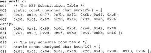
These two tables form the constant tables. The first is the SubBytes function implemented as a single table called sbox. The second table is the Rcon table for the key schedule, which is the first 10 powers of g(x) = x.
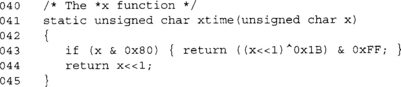
This function computes the xtime required for MixColumns. One possible tradeoff would be to implement this as a single 256-byte table. It would avoid the XOR, shift and branch, making the code faster at a cost of more fixed data usage.
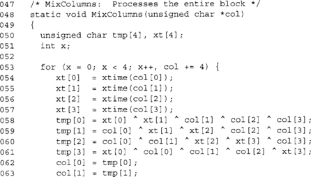
This is the MixColumn function we saw previously, except it has now been modified to work on all 16 bytes of the state. As previously noted, this function is also doubled buffered (copying to tmp[]) and can be optimized to avoid this. We are also using an array xt[] to hold copies of the xtime() output. Since it is used twice, caching it saves time. However, we do not actually need the array. If we first add all inputs, then the xtime() results, we only need a single byte of extra storage.
This function implements the ShiftRows function. It uses a single temporary byte t to swap around values in the rows. The second and fourth rows are implemented using essentially a shift register, while the third row is a pair of swaps.
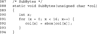
This function implements the SubBytes function. Fairly straightforward, not much to optimize here.
This functions implements AddRoundKey function. It reads the round key from a single array of bytes, which is at most 15*16=240 bytes in size. We shift the round number by four bits to the left to emulate a multiplication by 16.
This function can be optimized on platforms with words larger than eight bits by XORing multiple key bytes at a time. This is an optimization we shall see in the 32-bit code.

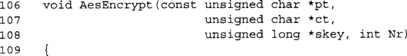
This function encrypts the block stored in blk in place using the scheduled secret key stored in key. The number of rounds used is stored in Nr and must be 10, 12, or 14 depending on the secret key length (of 128, 192, or 256 bits, respectively).
This implementation of AES is not terribly optimized, as we wished to show the discrete elements of AES in action. In particular, we have discrete steps inside the round. As we shall see later, even for eight-bit targets we can combine SubBytes, ShiftRows, and MixColumns into one step, saving the double buffering, permutation (ShiftRows), and lookups.

This key schedule is the direct translation of the AES standard key schedule into C using eight-bit data types. We have to emulate RotWords() with a shuffle, and all of the loads and stores are done with a four step for loop.
The obvious optimization is to create one loop per key size and do away with the remainder (%) operations. In the optimized key schedule, we shall see shortly a key can be scheduled in roughly 1,000 AMD64 cycles or less. A single division can take upward of 100 cycles, so removing that operation is a good starting point.
As with AddRoundKey on 32- and 64-bit platforms, we will implement the key schedule using full 32-bit words instead of 8-bit words. This allows us to efficiently implement RotWord() and the 32-bit XOR operations.
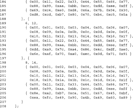
These three entries are the standard AES test vectors for 128, 192, and 256 key sizes.
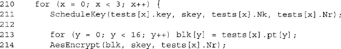
Here we are encrypting the plaintext (blk == pt), and are going to test if it equals the expected ciphertext.
This implementation will serve as our reference implementation. Let us now consider various optimizations.
Optimized Eight-Bit Implementation
We can remove several hotspots from our reference implementation.
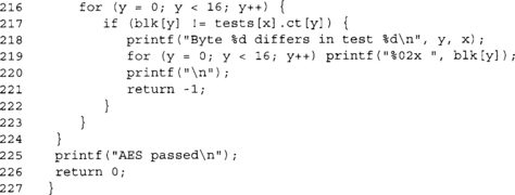
The new xtime table is listed here.
This lookup table will return the same result as the old function. Now we are saving on a function call, branch, and a few trivial logical operations.
Next, we mix ShiftRows and MixColumns into one function.
We did away with the double buffering tmp array and are outputting to a different destination. Next, we removed the xt array and replaced it with a single unsigned char.
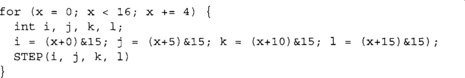
The entire function has been unrolled to make the array indexing faster. In various processors (such as the 8051), accessing the internal RAM by constants is a very fast (one cycle) operation. While this makes the code larger, it does achieve a nice performance boost. Implementers should map tmp and blk to IRAM space on 8051 series processors.
The indices passed to the STEP macro are from the AES block offset by the appropriate amount. Recall we are storing values in column major order. Without ShiftRows, the selection patterns would be {0,1,2,3}, {4,5,6,7}, and so on. Here we have merged the ShiftRows function into the code by renaming the bytes of the AES state. Now byte 1 becomes byte 5 (position 1,1 instead of 1,0), byte 2 becomes byte 10, and so on. This gives us the following selection patterns {0,5,10,15}, {4,9,14,3}, {8, 13, 2, 7}, and {12, 1,6, 11}.
![]()
This achieves a nearly 4x compression of the code when the compiler is smart enough to use CSE throughout the macro. For various embedded compilers, you may need to help it out by declaring i, j, k, and 1 as local ints. For example,
Now when the macro is expanded, the pre-computed values are used. Along with this change, we now need new SubBytes and AesEncrypt functions to accommodate the secondary output buffer.
Here we are still using a double buffering scheme (akin to page flipping in graphics programming), except we are not copying back the result without doing actual work. SubBytes stores the result in our local tmp array, and then ShiftMix outputs the data back to blk.
With all these changes, we can now remove the MixColumns function entirely. The code size difference is fairly trivial on x86 processors, where the optimized copy requires 298 more bytes of code space. Obviously, this does not easily translate into a code size delta on smaller, less capable processors. However, the performance delta should be more than worth it.
While not shown here, decryption can perform the same optimizations. It is recommended that if space is available, tables for the multiplications by 9, 11, 13, and 14 in GF(2)[x]/v(x) be performed by 256 byte tables, respectively. This adds 1,024 bytes to the code size but drastically improves performance.
Key Schedule Changes
Now that we have merged ShiftRows and MixColumns, decryption becomes a problem. In AES decryption, we are supposed to perform the AddRoundKey before the InvMixColumns step; however, with this optimization the only place to put it afterward2. (Technically, this is not true. With the correct permutation, we could place AddRoundKey before InvShiftRows.) However, the presented solution leads into the fast 32-bit implementation. If we let S represent the AES block, K represent the round key, and C the InvMixColumn matrix, we are supposed to compute C(S + K) = CS + CK. However, now we are left with computing CS + K if we add the round key afterward.
The solution is trivial. If we apply InvMixColumn to all of the round keys except the first and last, we can add it at the end of the round and still end up with CS + CK. With this fix, the decryption implementation can use the appropriate variation of ShiftMix() to perform ShiftRows and MixColumns in one step. The reader should take note of this fix, as it arises in the fast 32-bit implementation as well.
Optimized 32-Bit Implementation
Our 32-bit optimized implementation achieves very high performance given that it is in portable C. It is based off the standard reference code provided by the Rijndael team and is public domain. To make AES fast in 32-bit software, we have to merge SubBytes, ShiftRows, and MixColumns into a single shorter sequence of operations. We apply renaming to achieve ShiftRows and use a single set of four tables to perform SubBytes and MixColumns at once.
Precomputed Tables
The first things we need for our implementation are five tables, four of which are for the round function and one is for the last SubBytes (and can be used for the inverse key schedule).
The first four tables are the product of SubBytes and columns of the MDS transform.
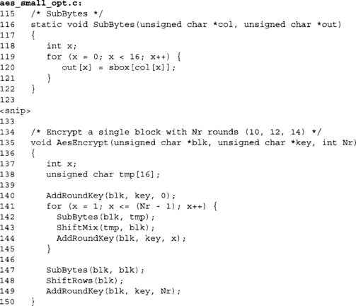
Where S(x) is the SubBytes transform and the product is a 1x1 * 1x4 matrix operation. From these tables, we can compute SubBytes and MixColumns with the following code:
The fifth table is simply the SubBytes function replicated four times; that is, Te4[x] = S(x) * [1, 1, 1, 1].
We note a space optimization (that also plays into the security of the implementation) is that the tables are simply rotated versions of each other’s. For example, Te1 [x] = RotWord(Te0[x]),Te2[x] = RotWord(Tel[x]), and so on. This means that we can compute Tel, Te2, and Te3 on the fly and save three kilobytes of memory (and possibly cache).
In our supplied code, we have Te0 and Te4 listed unconditionally. However, we provide the ability to remove Te1, Te2, and Te3 if desired with the define SMALL_CODE.

These two tables are our Te0 and Te4 tables. Note that we have named it TE0 (uppercase), as we shall use macros (below) to access the tables.

Here we see the definitions for our four tables. We have also split Te4 into four tables in the large code variation. This saves the logical AND operation required to extract the desired byte.
In the small code variation, we do not include TE1, TE2, or TE3, and instead use our cyclic rotation macro RORc (defined later) to emulate the tables required. We also construct the four Te4 tables by the required logical AND operation.
Decryption Tables
For decryption mode, we need a similar set of five tables, except they are the inverse.
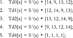
Where S−1(x) is InvSubBytes and the row matrices are the columns of InvMixColumns. From this, we can construct InvSubMix() using the previous technique.
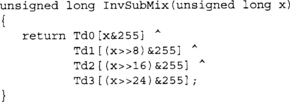
Macros
Our AES code uses a series of portable C macros to help work with the data types. Our first two macros, STORE32H and LOAD32H, were designed to help store and load 32-bit values as an array of bytes. AES uses big endian data types, and if we simply loaded 32-bit words, we would not get the correct results on many platforms. Our third macro, RORc, performs a cyclic shift right by a specified (nonconstant) number of bits. Our fourth and last macro, byte, extracts the n’th byte out of a 32-bit word.
These macros are fairly common between our cryptographic functions so they are handy to place in a common header for your cryptographic source code. These macros are actually the portable macros from the LibTomCrypt package. LibTomCrypt is a bit more advanced than this, in that it can autodetect various platforms and use faster equivalent macros (loading little endian words on x86 processors, for example) where appropriate.
On the ARM (and similar) series of processors, the byte() macro is not terribly efficient. The ARM7 (our platform of choice) can perform byte loads and stores into 32-bit registers. The previous macro can be safely changed to
![]()
on little endian platforms. On big endian platforms, replace [n] with [3–n].
Key Schedule
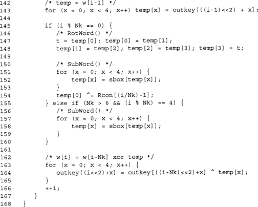
Our key schedule takes advantage of the fact that you can easily unroll the loop. We also perform all of the operations using (at least) 32-bit data types.
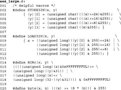
This computes the SubWord() function of the key schedule. It applies the SubBytes function to the bytes of temp in parallel. The Te4_n arrays are values from the Te4 array with all but the n’th byte masked off. For example, all of the words in Te4_3 only have the top eight bits nonzero.
This function performs RotWord() as well to the input by renaming the bytes of temp. Note, for example, how the byte going into Te4_3 is actually the third byte of the input (as opposed to the fourth byte).
This function differs from the eight-bit implementation in two ways. First, we pass the key length (keylen) in bytes, not 32-bit words. That is, valid values for keylen are 16, 24, and 32. The second difference is the output is stored in an array of 15*4 words instead of 15*16 bytes.
We always load the first 128 bits of the key regardless of the actual key size.

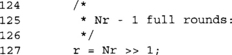
This loop computes the round keys for the 128-bit key mode. It is fully unrolled to produce one round key per iteration and avoids division completely.
The last two compute the 192- and 256-bit round keys, respectively. At this point, we now have our round keys required in the skey array. We will see later how to compute keys for decryption mode. The rest of the AES code implements the encryption mode.
Again, we deviate from the eight-bit code in that we read the plaintext from the pt array and store the ciphertext in the ct array. This implementation allows pt == ct so they can overlap if the caller chooses.
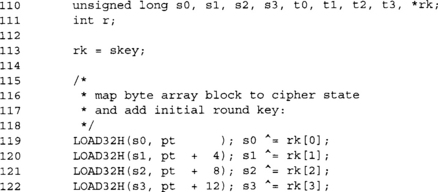
Here we load the block into the array [s0, s1, s2, s3] and then apply the first AddRoundKey at the same time.

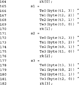
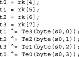
This is one complete AES round; we are encrypting the data in [s0,s1, s2,s3] into the set [t0,t1,t2,t3]. We can clearly see the four applications of SubBytes and MixColumns in the pattern of four Te array lookups and XORs.
The ShiftRows function is accomplished with the use of renaming. For example, the first output (for tO) is byte three of sO (byte zero of the AES input), byte two of s1 (byte five of the AES input), and so on. The next output (for t1) is the same pattern but shifted by four columns.
This same pattern of rounds is what we will use for decryption. We will get into the same trouble as the optimized eight-bit code in that we need to modify the round keys so we can apply it after MixColumns and still achieve the correct result.
This “break” allows us to exit the loop when we hit the last full round. Recall that AES has 9, 11, or 13 full rounds. We execute this loop up to Nr/2–1 times, which means we have to exit in the middle of the loop, not the end.

This code handles the even rounds. We are using [t0,t1,t2,t3] as the source and feeding back into [s0,s1,s2,s3]. The reader may note that we are using rk[0,1,2,3] as the round keys. This is because we enter the loop offset by 0 but should be by 4 (the first AddRoundKey). So, the first half of the loop uses rk[4,5,6,7], and the second half uses the lower words.
A simple way to collapse this code is to only use the first loop and finish each iteration with
![]()
This allows the implementation of the encryption mode to be roughly half the size at a slight cost in speed.
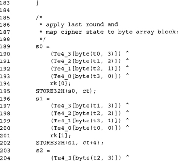

Here we are applying the last SubBytes, ShiftRows, and AddRoundKey to the block. We store the output to the ct array in big endian format.
Performance
This code achieves very respectable cycles per block counts with various compilers, including the GNU C and the Intel C compilers (Table 4.1).
Table 4.1
Comparisons of AES on Various Processors (GCC 4.1.1)
| Processor | Cycles per block encrypted [128-bit key] |
| AMD Opteron | 247 |
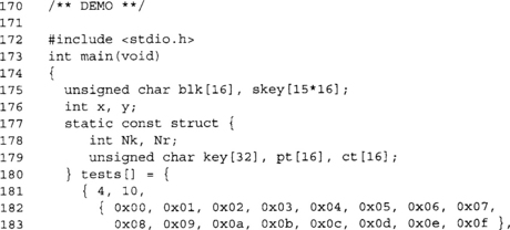
| Intel Pentium 540J | 450 |
| Intel Pentium M | 396 |
| ARM7TDMI | 3300 (Measured on a Nintendo GameBoy, which contains an ARM7TDMI processor at 16MHz. We put the AES code in the internal fast memory (IWRAM) and ran it from there.) |
| ARM7TDMI + Byte Modification | 1780 |
Even though the code performs well, it is not the best. Several commercial implementations have informally claimed upward of 14 cycles per byte (224 cycles per block) on Intel Pentium 4 processors. This figure seems rather hard to achieve, as AES-128 has at least 420 opcodes in the execution path. A result of 224 cycles per block would mean an instruction per cycle count of roughly 1.9, which is especially unheard of for this processor.
Even though the code performs well, it is not the best. Several commercial implementations have informally claimed upward of 14 cycles per byte (224 cycles per block) on Intel Pentium 4 processors. This figure seems rather hard to achieve, as AES-128 has at least 420 opcodes in the execution path. A result of 224 cycles per block would mean an instruction per cycle count of roughly 1.9, which is especially unheard of for this processor.
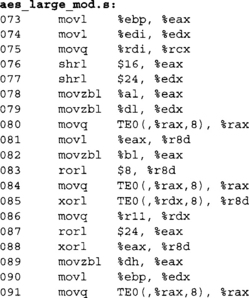
x86 Performance
The AMD Opteron achieves a nice boost due to the addition of the eight new general-purpose registers. If we examine the GCC output for x86_64 and x86_32 platforms, we can see a nice difference between the two (Table 4.2).

Both snippets accomplish (at least) the first MixColumns step of the first round in the loop. Note that the compiler has scheduled part of the second MixColumns during the first to achieve higher parallelism. Even though in Table 4.2 the x86_64 code looks longer, it executes faster, partially because it processes more of the second MixColumns in roughly the same time and makes good use of the extra registers.
From the x86_32 side, we can clearly see various spills to the stack (in bold). Each of those costs us three cycles (at a minimum) on the AMD processors (two cycles on most Intel processors). The 64-bit code was compiled to have zero stack spills during the main loop of rounds. The 32-bit code has about 15 stack spills during each round, which incurs a penalty of at least 45 cycles per round or 405 cycles over the course of the 9 full rounds.
Of course, we do not see the full penalty of 405 cycles, as more than one opcode is being executed at the same time. The penalty is also masked by parallel loads that are also on the critical path (such as loads from the Te tables or round key). Those delays occur anyways, so the fact that we are also loading (or storing to) the stack at the same time does not add to the cycle count.
In either case, we can improve upon the code that GCC (4.1.1 in this case) emits. In the 64-bit code, we see a pairing of “shrq $24, %rdx” and “and1 $255,%edx”. The andl operation is not required since only the lower 32 bits of %rdx are guaranteed to have anything in them. This potentially saves up to 36 cycles over the course of nine rounds (depending on how the andl operation pairs up with other opcodes).
With the 32-bit code, the double loads from (%esp) (lines 2 and 3) incur a needless three-cycle penalty. In the case of the AMD Athlon (and Opterons), the load store unit will short the load operation (in certain circumstances), but the load will always take at least three cycles. Changing the second load to “movl %edx,%ebx” means that we stall waiting for %edx, but the penalty is only one cycle, not three. That change alone will free up at most 9*2*4 = 72 cycles from the nine rounds.
ARM Performance
On the ARM platform, we cannot mix memory access opcodes with other operations as we can on the x86 side. The default byte() macro is actually pretty slow, at least with GCC 4.1.1 for the ARM7. To compile the round function, GCC tries to perform all quarter rounds all at once. The actual code listing is fairly long. However, with some coaxing, we can approximate a quarter round in the source.
Oddly enough, GCC is fairly smart. The first attempt commented out all but the first quarter round. GCC correctly identified that it was an endless loop and optimized the function to a simple
![]()
which endlessly loops upon itself. The second attempt puts the following code in the loop.
![]()
Again, GCC optimized this since the source variables s0, s1, s2, and s3 are not modified. So, we simply copied to over them all and got the following code, which is for exactly one

Here is an AES quarter round with the byte code optimization we mentioned earlier in the text.

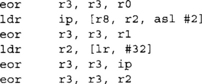
We can see the compiler easily uses the “load byte” ldrb instruction to isolate bytes of the 32-bit words to get indexes into the tables. Since this is ARM code, it can make use of the inline “asl #2”, which multiplies the indices by four to access the table. Overall, the optimized code has three fewer opcodes per quarter round. So, why is it faster? Consider the number of memory operations per round (Table 4.3).
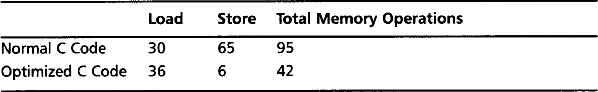
Even though we have placed our data in the fast 32-bit internal memory on the GameBoy (our test platform), it still takes numerous cycles to access it. According to the various nonofficial datasheets covering this platform, a load requires three cycles if the access are not sequential, and a store requires two cycles. The memory operations alone contribute 100 cycles per round above the optimized code; this accounts for 1000 cycles over the entire enciphering process.
The code could, in theory, be made faster by using each source word before moving on to the next. In our reference code, we compute whole 32-bit words of the round function at a time by reading bytes from the four other words in a row. For example, consider this quarter round
Ideally, the compiler aliases t0, t1, t2, and t3 to ARM processor registers. In this approach, we are accessing the bytes of the words sequentially. The next quarter round would use the bytes of s1 in turn. In this way, all memory accesses are sequential.
Performance of the Small Variant
Now we consider the performance using the smaller tables and a rolled up encrypt function. This code is meant to be deployed where code space is at a premium, and works particularly well with processors such as the ARM series (Table 4.4).
Table 4.4
Comparison of AES with Small and Large Code on an AMD Opteron
| Mode | Cycles per block encrypted (128-bit key) |
| Large Code | 247 |
| Small Code | 325 |
An interesting thing to point out is how GCC treats our rotations. With the aes_large.c code and the SMALL_CODE symbol defined, we get the following quarter round.

As we can see, GCC is doing a 32-bit rotation with a 64-bit data type. The same code compiled in 32-bit mode yields the following quarter round.
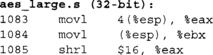
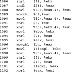
Here we can clearly see that GCC picks up on the rotation and uses a nice constant “rorl” instruction in place of all the shifts, ANDs, and ORs. The solution for the 64-bit case is simple; use a 32-bit data type. At least for GCC, the symbol __x86_64___ is defined for 64–bit x86_64 mode. If we insert the following code at the top and replace all “unsigned long” references with “ulong32,” we can support both 32- and 64-bit modes.
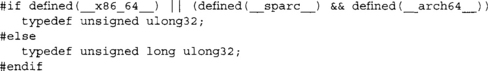
We have also added a common define combination for SPARC machines to spruce up the code snippet. Now with the substitutions in place, we see that GCC has a very good time optimizing our code.

Inverse Key Schedule
So far, we have only considered the forward mode. The inverse cipher looks exactly the dame, at least for this style of implementation. The key difference is that we substitute the forward tables with the inverse. This leaves us with the key schedule.
In the standard AES reference code, the key schedule does not change for the inverse cipher, since we must apply AddRoundKey before InvMixColumns. However, in this style of implementation, we are performing the majority of the round function in a single short sequence of operations. We cannot insert AddRoundKey in between so we must place it afterward.
The solution is to perform two steps to the forward round keys.
1. Reverse the array of round keys.
2. Apply InvMixColumns to all but the first and last round keys.
To reverse the keys, we do not actually form 128-bit words; instead, we do the swaps logically with 32-bit words. The following C code will reverse the keys in rk to drk.
Now we have the keys in the opposite order in the drk array. Next, we have to apply InvMixColumns. At this point, we do not have a cheap way to implement that function. Our tables Td0, Td1, Td2, and Td3 actually implement InvSubBytes and InvMixColumns. However, we do have a SubBytes table handy (Te4). If we first pass the bytes of the key through Te4, then through the optimized inverse routine, we end up with
![]()
which can be implemented in the following manner.
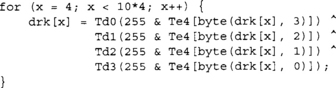
Now we have the proper inverse key schedule for AES-128. Substitute “10*4” by “12*4” or “14*4” for 192- or 256-bit keys, respectively.
Practical Attacks
As of this writing, there are no known breaks against the math of the AES block cipher. That is, given no other piece of information other than the traditional plaintext and ciphertext mappings, there is no known way of determining the key faster than brute force.
However, that does not mean AES is perfect. Our “classic” 32-bit implementation, while very fast and efficient, leaks considerable side channel data. Two independent attacks developed by Bernstein and Osvik (et al.) exploit this implementation in what is known as a side channel attack.
Side Channels
To understand the attacks we need to understand what a side channel is. When we run the AES cipher, we produce an output called the ciphertext (or plaintext depending on the direction). However, the implementation also produces other measurable pieces of information. The execution of the cipher does not take fixed time or consume a fixed amount of energy.
In the information theoretic sense, the fact that it does not take constant time means that the implementation leaks information (entropy) about the internal state of the algorithm (and the device it is running on). If the attacker can correlate runtimes with the knowledge of the implementation, he can, at least in theory, extract information about the key.
So why would our implementation not have a constant execution time? There are two predominantly exploitable weaknesses of the typical processor cache.
Processor Caches
A processor cache is where a processor stores recently written or read values instead of relying on main system memory. Caches are designed in all sorts of shapes and sizes, but have several classic characteristics that make them easy to exploit. Caches typically have a low set associativity, and make use of bank selectors.
Associative Caches
Inside a typical processor cache, a given physical (or logical depending on the design) address has to map to a location within the cache. They typically work with units of memory known as cache lines, which range in size from small 16-byte lines to more typical 64- and even 128-byte lines. If two source addresses (or cache lines) map to the same cache address, one of them has to be evicted from the cache. The eviction means that the lost source address must be fetched from memory the next time it is used.
In a fully associated cache (also known as a completely associated memory or CAM), a source address can map anywhere inside the cache. This yields a high cache hit rate as evictions occur less frequently. This type of cache is expensive (in terms of die space) and slower to implement. Raising the latency of a cache hit is usually not worth the minor savings in the cache miss penalties you would have otherwise.
In a set-associative cache, a given source address can map to one of N unique locations; this is also known as a N-way associative cache. These caches are cheaper to implement, as you only have to compare along the N ways of the cache for a cache line to evict. This lowers the latency of using the cache, but makes a cache eviction more likely.
The cheapest way to compute a cache address in the set-associative model is to use consecutive bits of the address as a cache address. These are typically taken from the middle of the address, as the lower bits are used for index and bank selection. These details depend highly on the configuration of the cache and the architecture in general.
Cache Organization
The organization of the cache affects how efficiently you can access it. We will consider the AMD Opteron cache design (AMD Software Optimization Guide for AMD64 Processors, #25112, Rev 3.06, September 2005) for this section, but much of the discussion applies to other processors.
The AMD Opteron splits addresses into several portions:
These values come from the L1 cache design, which is a 64-kilobyte two-way set-associative cache. The cache is actually organized as two linear arrays of 32 kilobytes in two ways (hence 64 kilobytes in total). The index value selects which 64 byte cache line to use, bank selects which eight-byte group of the cache line, and byte indicates the starting location of the read inside the eight-byte group.
The cache is dual ported, which means two reads can be performed per cycle; that is, unless a bank conflict occurs. The processor moves data in the cache on parallel busses. This means that all bank 0 transactions occur on one bus, bank 1 transactions on another, and so on. A conflict occurs when two reads are from the same bank but different index. What that means is you are reading from the same bank offset of two different cache lines. For example, using AT&T syntax, the following code would have a bank conflict.
![]()
Assuming that both addresses are in the L1 cache and %eax is aligned on a four-byte boundary, this code will exhibit a bank conflict penalty. Effectively, we want to avoid reads that a proper multiple of 64 offsets, which, as we will see, is rather unfortunate for our implementation.
Bernstein Attack
Bernstein was the first to describe a complete cache attack against AES3 (although it is seemingly bizarre, it does in fact work) using knowledge of the implementation and the platform it was running on. (He later wrote a follow-up paper at http://cr.yp.to/antiforgery/cachetiming-20050414.pdf.) His attack works as follows.
1. Pick one of the 16 plaintext bytes, call that pt[n].
2. Go through all 256 possible values of pt[n] and see which takes the longest to encrypt.
This attack relies on the fact that pt[n] XOR key[n] will be going into the first round tables directly. You first run the attack with a known key. You deduce a value T = pt[n] XOR key[n], which occurs the most often. That is, you will see other values of T, but one value will eventually emerge as the most common. Now, you run the attack against the victims by having them repeatedly encrypt plaintexts of your choosing. You will end up with a value of pt[n] for which the delay is the longest and then can deduce that pt[n] XOR T = key[n].
The attack seems like it would not work and indeed it is not without its flaws. However, over sufficiently long enough runs it will yield a stable value of T for almost all key bytes. So why does the attack work? There are two reasons, which can both be true depending on the circumstances.
In the first case, one of our tables had a cache line evicted due to another process competing for the cache line. This can arise due to another task (as in the case of the Osvik attack) or kernel process interrupting the encryption. Most processors (including the Pentium 4 with its small 8–16KB L1 cache) can fit the entire four kilobytes of tables in the L1 cache. Therefore, back-to-back executions should have few cache line evictions if the OS (or the calling process) does not evict them.
The more likely reason the attack succeeds is due to a bank conflict, changing the value of pt[n] until it conflicts with another lookup in the same quarter round of AES. All of the tables are 1024 bytes apart, which is a proper multiple of 64. This means that, if you access the same 32-bit word (or its neighbor) as another access, you will incur the stall.
Bernstein proposed several solutions to the problem, but the most practical is to serialize all loads. On the AMD processors are three integer pipelines, each of which can issue a load or store per cycle (a maximum of two will be processed, though). The fix is then to bundle instructions in groups of three and ensure that the loads and stores all occur in the same location within the bundles. This fix also requires that instructions do not cross the 16-byte boundary on which the processor fetches instructions. Padding with various lengths of no operation (NOP) opcodes can ensure the alignment is maintained.
This fix is the most difficult to apply, as it requires the implementer to dive down in to assembler. It is also not portable, even across the family of x86 processors. It also is not even an issue on certain processors that are single scalar (such as the ARM series).
Osvik Attack
The Osvik (Dag Arne Osvik, Adi Shamir, and Eran Tromer: Cache Attacks and Countermeasures: the Case of AES) attack is a much more active attack than the Bernstein attack. Where in the Bernstein attack you simply try to observe encryption time, in this attack you are actively trying to evict things out of the cache to influence timing.
Their attack is similar to the attack of Colin Percival (Colin Percival: Cache Missing For Fun and Profit) where a second process on the victim machine is actively populating specific cache lines in the hopes of influencing the encryption routine. The goal is to know which lines to evict and how to correlate them to key bits. In their attack, they can read 47 bits of key material in one minute.
Countering this attack is a bit harder than the Bernstein attack. Forcing serialized loads is not enough, since that will not stop cache misses. In their paper, they suggest a variety of changes to mitigate the attack; that is, not to defeat the attack but make it impractical.
Defeating Side Channels
Whether these side channels are even a threat depends solely on your application’s threat model and use cases. It is unwise to make a blanket statement we must defend against all side channels at all times. First, it’s impractically nonportable to do so. Second, it’s costly to defend against things that are not threats, and often you will not get the time to do so. Remember, you have customers to provide a product to.
The attacks are usually not that practical. For example, Bernstein’s attack, while effective in theory, is hard to use in practice, as it requires the ability to perform millions of chosen queries to an encryption routine, and a low latency channel to observe the encryptions on. As we will see with authenticated channels, requesting encryptions from an unauthorized party can easily be avoided. We simply force the requestors to authenticate their requests, and if the authentication fails, we terminate the session (and possibly block the attackers from further communication). The attack also requires a low latency channel so the timings observed are nicely correlated. This is possible in a lab setting where the two machines (attacker and victim) are on the same backplane. It is completely another story if they are across the Internet through a dozen hops going from one transmission medium to another.
The Osvik attack requires an attacker to have the ability to run processes locally on the victim machine. The simplest solution if you are running a server is not to allow users to have a shell on the machine.
Little Help from the Kernel
Suppose you have weeded out the erroneous threat elements and still think a cache smashing attack is a problem. There is still a feasible solution without designing new processors or other impractical solutions. Currently, no project provides this solution, but there is no real reason why it would not work.
Start with a kernel driver (module, device driver, etc.) that implements a serialized AES that preloads the tables into L1 before processing data. That is, all accesses to the tables are forced into a given pipeline (or load store unit pipeline). This is highly specific to the line of processor and will vary from one architecture to another.
Next, implement a double buffering scheme where you load the text to be processed into a buffer that is cacheable and will not compete with the AES tables. For example, on the AMD processors all you have to do is ensure that your buffer does not have an overlap with the tables modulo 32768. For example, the tables take 5 kilobytes, leaving us with 27 kilobytes to store data.
Now to process a block of data, the kernel is passed the data to encrypt (or decrypt), and locks the machine (stopping all other processors). Next, the processor crams as much as possible into the buffer (looping as required to fulfill the request), preloads it into the L1, and then proceeds to process the data with AES (in a chaining mode as appropriate).
This approach would defeat both Bernstein’s and Osvik’s attacks, as there are no bank conflicts and there is no way to push lines out of the L1. Clearly, this solution would lead to a host of denial of service (DoS) problems, as an attacker could request very large encryptions to lock up the machine. A solution to that problem would be to either require certain users’ identifiers to use the device or restrict the maximum size of data allowed. A value as small as 4 to 16 kilobytes would be sufficient to make the device practical.
Chaining Modes
Ciphers on their own are fairly useless as privacy primitives. Encrypting data directly with the cipher is a mode known as Electronic Codebook (ECB). This mode fails to achieve privacy, as it leaks information about the plaintext. The goal of a good chaining mode is therefore to provide more privacy than ECB mode. One thing a good chaining mode is not for is authenticity. This is a point that cannot be stressed enough and will be repeated later in the text.
Repeatedly, we see people write security software where they implement the privacy primitive but fail to ensure the authenticity—either due to ignorance or incompetence. Worse, people use modes such as CBC and assume it provides authenticity as well.
ECB mode fails to achieve privacy for the simple fact that it leaks information if the same plaintext block is ever encrypted more than once. This can occur within the same session (e.g., a file) and across different sessions. For example, if a server responds to a query with a limited subset of responses all encrypted in ECB mode, the attacker has a very small mapping to decode to learn the responses given out.
To see this, consider a credit-card authorization message. At its most basic level, the response is either success or failure; 0 or 1. If we encrypted these status messages with ECB, it would not take an attacker many transactions to work out what the code word for success or failure was.
Back in the days of DES, there were many popular chaining modes, from Ciphertext Feedback (CFB), Output Feedback (OFB), and Cipher Block Chaining (CBC). Today, the most common modes are cipher block chaining and counter mode (CTR). They are part of the NIST SP 800–38A standard (and OFB and CFB modes) and are used in other protocols (CTR mode is used in GCM and CCM, CBC mode is used in CCM and CMAC).
Cipher Block Chaining
Cipher block chaining (CBC) mode is most common legacy encryption mode. It is simple to understand and trivial to implement around an existing ECB mode cipher implementation. It is often mistakenly attributed with providing authenticity for the reason that “a change in the ciphertext will make a nontrivial change in the plaintext.” It is true that changing a single bit of ciphertext will alter two blocks of plaintext in a nontrivial fashion. It is not true that this provides authenticity.
We can see in Figure 4.12 that we encrypt the plaintext blocks P[0,1,2] by first XORing a value against the block and then encrypting it. For blocks P[1,2], we use the previous ciphertext C[0,1] as the chaining value. How do we deal with the first block then, as there is no previous ciphertext? To solve this problem, we use an initial value (IV) to serve as the chaining value. The message is then transmitted as the ciphertext blocks C[0,1,2] and the IV.

What’s in an IV?
An initial value, at least for CBC mode, must be randomly chosen but it need not be secret. It must be the same length of the cipher block size (e.g., 16 bytes for AES).
There are two common ways of dealing with the storage (or transmission) of the IV. The simplest method is to generate an IV at random and store it with the message. This increases the size of the message by a single block.
The other common way of dealing with the IV is to make it during the key negotiation process. Using an algorithm known as PKCS #5 (see Chapter 5), we can see that from a randomly generated shared secret we can derive both encryption keys and chaining IVs.
Message Lengths
The diagram (Figure 4.12) suggests that all messages have to be a proper multiple of the cipher block size. This is not true. There are two commonly suggested (both equally valid) solutions. FIPS 81 (which is the guiding doctrine for SP 800–38A) does not mandate a solution, unfortunately.
The first common solution is to use a technique known as ciphertext stealing. In this approach, you pass the last ciphertext block through the cipher in ECB mode and XOR the output of that against the remaining message bytes (or bits). This avoids lengthening the message (beyond adding the IV).
The second solution is to pad the last block with enough zero bits to make the message length a proper multiple of the cipher block size. This increases the message size and really has no benefits over ciphertext stealing.
In practice, no standard from NIST mandates one solution over the other. The best practice is to default to ciphertext stealing, but document the fact you chose that mode, unless you have another standard to which you are trying to adhere.
Decryption
To decrypt in CBC mode, pass the ciphertext through the inverse cipher and then XOR the chaining value against the output (Figure 4.13).
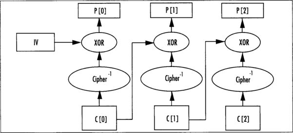
Performance Downsides
CBC mode suffers from a serialization problem during encryption. The ciphertext C[n] cannot be computed until C[n–1] is known, which prevents the cipher from being invoked in parallel. Decryption can be performed in parallel, as the ciphertexts are all known at that point.
Implementation
Using our fast 32-bit AES as a model, we can implement CBC mode as follows.
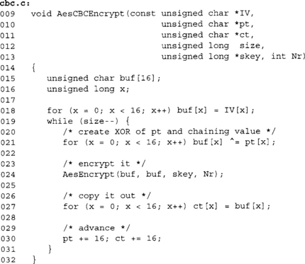
This code performs the CBC updates on a byte basis. In practice, it’s faster and mostly portable to perform the XORs as whole words at once. On x86 processors, it’s possible to use 32- or 64-bit words to perform the XORs (line 21). This dramatically improves the performance of the CBC code and reduces the overhead over the raw ECB mode.
Decryption is a bit trickier if we allow pt to equal ct.
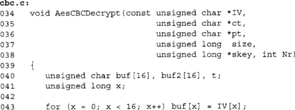
Here we again use buf as the chaining buffer. We decrypt through AES ECB mode to buf2, since at this point we cannot write to pt directly. Inside the inner loop (lines 49 to 53), we fetch a byte of ct before we overwrite the same position in pt. This allows the buffers to overlap without losing the previous ciphertext block required to decrypt in CBC mode.
Counter Mode
Counter mode (CTR) is designed to extract the maximum efficiency of the cipher to achieve privacy. In this mode, we make use of the fact that the cipher should be a good pseudo random permutation (PRP). Instead of encrypting the message by passing it through the cipher, we encrypt it as we would with a stream cipher.
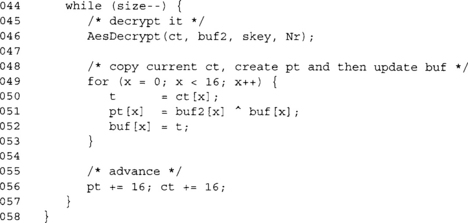
In CTR mode, we have an IV as we would for CBC, except it does not have to be random, merely unique. The IV is encrypted and XORed against the first plaintext block to produce the first ciphertext. The IV is then incremented (as if it were one large integer), and then the process is repeated for the next plaintext block (Figure 4.14).
The “increment” function as specified by SP800–38A is a simple binary addition of the value “1.” The standard does not specify if the string is big or little endian. Experience shows that most standards assume it is big endian (that is, you increment byte 15 of the chaining value and the carries propagate toward byte 0).
The standard SP800–38A allows permutation functions other than the increment. For example, in hardware, a LFSR stepping (see Chapter 3) would be faster than an addition since there are no carries. The standard is clear, though, that all chaining values used with the same secret key must be unique.
Message Lengths
In the case of CTR, we are merely XORing the output of the cipher against the plaintext. This means there is no inherit reason why the plaintext has to be a multiple of the cipher block size. CTR mode is just as good for one-bit messages as it is terabit messages.
CTR mode requires that the IV be transmitted along with the ciphertext—so there is still that initial message expansion to deal with. In the same way that CBC IVs can be derived from key material, the same is true for CTR mode.
Decryption
In CTR mode, encryption and decryption are the same process. This makes implementations simpler, as there is less code to deal with. Also, unlike CBC mode, only the forward direction of the cipher is required. An implementation can further save space by not including the ECB decryption mode support.
Performance
CTR mode allows for parallel encryption or decryption. This is less important in software designs, but more so in hardware where you can easily have one, two, or many cipher “cores” creating a linear improvement in throughput.
Security
CTR mode strongly depends on the chaining values being unique. This is because if you reuse a chaining value, the XOR of two ciphertext blocks will be the XOR of the plaintext blocks. In many circumstances, for example, when encrypting English ASCII text, this is sufficient to learn the contents of both blocks. (You would expect on average that 32 bytes of English ASCII have 41.6 bits of entropy, which is less than the size of a single plaintext block.)
The simplest solution to this problem, other than generating IVs at random, is never to reuse the same key. This can be accomplished with fairly modest key generation protocols (see Chapter 5).
Implementation
Again, we have used the 32-bit fast AES code to construct another chaining mode; this time, the CTR chaining mode.

In this implementation, we are again working on the byte level to demonstrate the mode. The XORs on line 28 could more efficiently be accomplished with a set of XORs with larger data types. The increment (lines 21 through 23) performs a big endian increment by one. The increment works because a carry will only occur if the value of (++IV[z] & 255) is zero. Therefore, if it is nonzero, there is no carry to propagate and the loop should terminate.
Here we also deviate from CBC mode in that we do not have specific plaintext and ciphertext variables. This function can be used to both encrypt and decrypt. We also update the IV value, allowing the function to be called multiple times with the same key as need be.
Choosing a Chaining Mode
Choosing between CBC and CTR mode is fairly simple. They are both relatively the same speed in most software implementations. CTR is more flexible in that it can natively support any length plaintext without padding or ciphertext stealing. CBC is a bit more established in existing standards, on the other hand.
A simple rule thumb is, unless you have to use CBC mode, choose CT1K instead.
Putting It All Together
The first thing to keep in mind when using ciphers, at least in either CTR or CBC mode, is to ignore the concept of authenticity. Neither mode will grant you any guarantee. A common misconception is that CBC is safer in this regard. This is not true. What you will want to use CBC or CTR mode for is establishing a private communication medium.
Another important lesson is that you almost certainly do need authenticity. This means you will be using a MAC algorithm (see Chapter 6) along with your cipher in CBC or CTR mode. Authentication is vital to protect your assets, and to protect against a variety of random oracle attacks (Bernstein and Osviks attacks). The only time authenticity is not an issue is if there is no point at which an attacker can alter the message. That said, it is a nice safety net to ensure authenticity for the user and in the end it usually is not that costly.
Now that we have that important lesson out of the way, we can get to deploying our block cipher and chaining mode(s). The first thing we need to be able to do is key the cipher, and to do so securely. Where and how we derive the cipher key is a big question that depends on how the application is to be used. The next thing we have to be able to do is generate a suitable IV for the chaining mode, a step that is often tied to the key generation step.
Keying Your Cipher
It is very important that the cipher be keyed with as much entropy as possible. There is little point of using AES if your key has 10 bits of entropy. Brute force would be trivial and you would be providing no privacy for your users. Always use the maximum size your application can tolerate. AES mandates you use at least a 128-bit key. If your application can tolerate the performance hit, you are better off choosing a larger key. This ensures any bias in your PRNG (or RNG) will still allow for a higher amount of entropy in the cipher key.
Forget about embedding the key in your application. It just will not work.
The most common way of keying a cipher is from what is known as a master key, but is also known as a shared secret. For example, a salted password hash (see Chapter 4) can provide a master key, and a public key encrypted random key (see Chapter 9) can provide a shared secret.
Once we have this master key, we can use a key derivation algorithm such as PKCS #5 (see Chapter 4) to derive a key for our cipher and an IV. Since the master key should be random for every session (that is, each time a new message is to be processed), the derived cipher key and IV should be random as well (Figure 4.15).
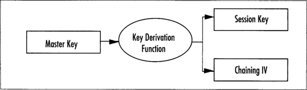
It is important that you do not derive your cipher key (session key) from something as trivial as a password directly. Some form of key derivation should always be in your cryptosystems pipeline.
ReKeying Your Cipher
Just as important as safely keying your cipher is the process of rekeying it. It is generally not a safe practice to use the same cipher key for a significant length of time. Formally, the limitations fall along the birthday paradox boundaries (264 blocks for AES). However, the value of all the secrets you can encrypt in that time usually outweighs the cost of supporting secure rekeying.
Rekeying can take various forms depending on if the protocol is online or offline. If the protocol is online, the rekeying should be triggered both on a timed and traffic basis; that is, after an elapsed time and after an elapsed traffic volume count has been observed. All signals to rekey should be properly authenticated just like any other message in the system. If the system is offline, the process is much simpler, as only one party has to agree to change keys. Reasonable guidelines depend on the product and the threat vectors, especially since the threat comes not from the cipher being broken but the key being determined through other means such as side channel attacks or protocol breaks.
Once the decision to rekey has been accepted (or just taken), it is important to properly rekey the cipher. The goal of rekeying is to mitigate the damages that would arise if an attacker learned the cipher key. This means that the new key cannot be derived from the previous cipher key. However, if you are clever and derived your cipher key from a master key, your world has become much easier.
At this point, an attacker would have at most a short amount of key derivation output, very unlikely to be enough to break the key derivation function. Using the key derivation function to generate a new cipher key at given intervals solves our problem nicely.
Bi-Directional Channels
A useful trick when initiating bi-directional channels is to have two key and IV pairs generated (ideally from a suitable key derivation function). Both parties would generate the same pair of keys, but use them in the opposite order. This has both cryptographic and practical benefits to it.
On the practical side, this allows both parties to send at once and to keep the IVs synchronized. It also makes dealing with lost packets (say from a UDP connection) easier.
On the cryptographic side, this reduces the traffic used under a given symmetric key. Assuming both sides transmit roughly an equal amount of traffic, the attacker now has half the ciphertext under a given key to look at.
Lossy Channels
On certain channels of communication such as UDP, packets can be lost, or worse, arrive out of order. First, let’s examine how to deal with packet data.
In the ideal protocol, especially when using UDP, the protocol should be able to cope with a minor amount of traffic loss, either by just ignoring the missing data or requesting retransmissions. In cases where latency is an issue, UDP is usually the protocol of choice for transmitting data. Don’t be mistaken that TCP is a secure transport protocol. Even though it makes use of checksums and counters, packets can easily be modified by an attacker. All data received should be suspect. To cope with loss, each packet must be independent. This means that each packet should have its own IV attached to it.
If we are using CBC mode, this means that each packet needs a fresh random IV. Since the IV is random, we will have to also attach a counter to it. The counter would be unique and incremented for every packet. It allows the receiver to know if it has seen the packet before, and if not, where in the stream of packets it belongs. At the very least, this implies a packet overhead of at least 20 bytes (for AES) per packet; that is, 16 bytes for the IV and 4 bytes (say) for the counter.
If we are using CTR mode, each packet needs a unique IV. There is no reason why the IV itself cannot be the packet counter. There is also no reason why the IV needs to be large if the key was chosen at random. For example, if we know we are going to send less than 232 packets, we could use a 4 byte counter, leaving the lower 12 bytes of the counter as implicitly zero (to be incremented during the encryption of the packet). This would add an overhead of only four bytes per packet. For more details on streaming protocols, see Chapter 6.
Now that we have counters on all of our packets, we can do two things with them. We can reject old or replayed packets, and we can sort out-of-order packets. There are two logical ways of dealing with out-of-order packets. The first is to just bump the counter up to the highest valid packet (disregarding any packets with lower counter values). This is the simplest solution and in many applications totally feasible. (Despite the bad reputation, UDP packets rarely arrive out of order.) So, in the rare event that it does occur, tolerating the error should be minor. The more difficult solution is to maintain a sliding window. The window would count upward from a given base, sliding the base as the situation arises.
For example, consider the following code:
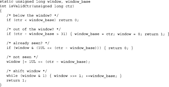
The preceding code allows the caller to keep track up to 32 numbered packets at once. It rejects old and previously seen packets, adjusts to bumps in the counter, and slides the window when possible. The caller would pass this function a counter from an otherwise valid function (a packet that has been authenticated; see Chapter 6), and it would return 0 if the counter is valid or 1 if not.
Myths
Here are some popular myths about block ciphers.
![]() CBC provides authenticity (or integrity).
CBC provides authenticity (or integrity).
![]() CBC requires only a unique IV, not a random one.
CBC requires only a unique IV, not a random one.
![]() CTR mode is not secure because the plaintext does not pass through the cipher itself.
CTR mode is not secure because the plaintext does not pass through the cipher itself.
![]() You can use data hidden in the application as a cipher key.
You can use data hidden in the application as a cipher key.
![]() Modifying the algorithm (to make the details obfuscated) makes it more secure.
Modifying the algorithm (to make the details obfuscated) makes it more secure.
CBC mode does not provide authenticity (sorry for the repetition, but this is a point many people get it wrong). If you want authenticity (and you usually do), apply a MAC to the message (or ciphertext) as well. CBC mode also requires unpredictable IVs, not merely unique ones.
CTR mode provably reduces the security of the block cipher. That is, if CTR mode is insecure so, are the CBC, OFB, and CFB modes.
Embedding a cipher key in the application is a trick people seem to like. Diebold was one of these types; except the source code was leaked and the key was found (and put on display, it was “F2654hD4” btw). Do not do this.
Modifying the cipher to achieve some proprietary tweak is another faux pas. It frustrates users by disallowing interoperability, can make the algorithm less secure, and in the end someone is going to reverse engineer it anyway.
Using the largest key size is not always “more secure” or better practice. It is a good idea, at least in theory. For example, if your RNG has a slight bias, then a 256-bit string it generates will have more entropy (at least on average) than a 128-bit string. However, 256–bit keys are slower in AES (14 rounds versus 10 rounds), and often RNGs or PRNGs are working as desired. Brute forcing a 128-bit key remains out of the realm of possibility for the foreseeable future.
The key reason why bigger is not always better is because it is easier to find attacks faster than brute-force for ciphers with larger keys. Consider using AES with a 64-bit key. To break the algorithm, you have to find an attack that works faster than 264 encryptions. This is a much harder proposition than breaking the full-length key. The key length of the cipher sends an expectation of how much security the designer claims the algorithm can offer.
Encrypting multiple times, possibly with different ciphers, does not create a safer mix; it just makes a slower design. The same logic that says “different ciphers applied multiple times makes it more secure” can also say, “The specific combination of these ciphers makes it insecure.” There is no reason to believe one argument over the other, and in the end you just create more proprietary junk.
Again, this is a easy to see. A block cipher is just shorthand notation for a huge substitution table. Given any particular substitution, it is always possible to find another complement substitution such that when applied one after another together will result in a linear transform. This construction is trivially breakable.
Providers
There are many readily available providers of AES encryption and decryption. In general, unless your application has very specific needs, you are better served (and serving your users) by not dwelling on the implementation. LibTomCrypt and OpenSSL are common providers in C callable applications. We shall use the former to create a simple CTR mode example.
The reader is encouraged to read the user manual that comes with LibTomCrypt to fully appreciate what the library has to offer. What follows is a simple program that will encrypt and decrypt a short string with AES in CTR mode.
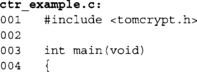
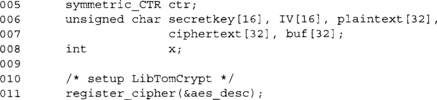
This statement tells LibTomCrypt to register the AES plug-in with its internal tables. LibTomCrypt uses a modular plug-in system to allow the developer to substitute one implementation with another (say for added hardware support). In this case, we are using the built-in AES software implementation.
![]()
Obviously, we left this section blank. The key and IV can be derived in many ways, most of which we haven’t shown you how to use yet. Chapter 5 shows how to use PKCS #5 as a key derivation function, and Chapter 9 shows how to use a public key algorithm to distribute a shared secret.
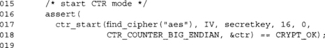
This function call initializes the ctr structure with the parameters for an AES-128 CTR mode encryption with the given IV. We have chosen a big endian counter to be nice and portable. This function can fail, and while there are many ways to deal with errors (such as more graceful reporting), here we simply used an assertation. In reality, this code should never fail, but as you put code like this in larger applications, it is entirely possible that it may fail.
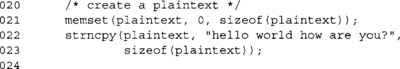
We zero the entire buffer plaintext before copying our shorter string into it. This ensures that we have zero bytes in the eventual decryption we intend to display to the user.
![]()
This function call performs AES-128 CTR mode encryption of plaintext and stores it in ciphertext. In this case, we are encrypting 32 bytes. Note, however, the CTR mode is not restricted to dealing with multiples of the block size. We could have easily resized the buffers to 30 bytes and still call the function (substituting 30 for 32).
The ctr_encrypt function can be called as many times as required to encrypt the plaintext. Each time the same CTR structure is passed in, it is updated so that the next call will proceed from the point the previous call left off. For example,
![]()
![]()

Before we can decrypt the text with the same CTR structure, we have to reset the IV. This is because after encrypting the plaintext the chaining value stored in the CTR structure has changed. If we attempted to decrypt it now, it would not work.
We use the ctr_decrypt function to perform the decryption from ciphertext to the buf array. For the curious, ctr_decrypt is just a placeholder that eventually calls ctr_encrypt to perform the decryption.
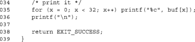
At this point, the user should be presented with the string “hello world how are you?” and the program should terminate normally.
The following Frequently Asked Questions, answered by the authors of this book, are designed to both measure your understanding of the concepts presented in this chapter and to assist you with real-life implementation of these concepts. To have your questions about this chapter answered by the author, browse to www.syngress.com/solutions and click on the “Ask the Author” form.
A: A cipher is an algorithm that transforms an input (plaintext) into an output (ciphertext) with a secret key.
Q: What is the purpose of a cipher?
A: The first and foremost purpose of a cipher is to provide privacy to the user. This is accomplished by controlling the mapping from plaintext to ciphertext with a secret key.
Q: What standards are there for ciphers?
A: The Advanced Encryption Standard (AES) is specified in FIPS 197. The NIST standard SP 800–38A specifies five chaining modes, including CBC and CTR mode.
Q: What about the other ciphers?
A: Formally, NIST still recognizes Skipjack (FIPS 185) as a valid cipher. It is slower than AES, but well suited for small 8- and 16-bit processor due to the size and use of 8-bit operations. In Canada, the CSE (Communication Security Establishment) formally recognizes CAST4 (CSE Web site of approved ciphers is at www.cse-cst.gc.ca/services/crypto-services/crypto-algorithms-e.html) in addition to all NIST approved modes. CAST5 is roughly as fast as AES, but nowhere near as flexible in terms of implementation. It is larger and harder to implement in hardware. Other common ciphers such as RC5, RC6, Blowfish, Twofish, and Serpent are parts of RFCs of one form or another, but are not part of official government standards. In the European Union, the NESSIE project selected Anubis and Khazad as its 128-bit and 64-bit block ciphers. Most countries formally recognize Rijndael (or often even AES) as their officially standardized block cipher.
Q: Where can I find implementations of ciphers such as AES?
A: Many libraries already support vast arrays of ciphers. LibTomCrypt supports a good mix of standard ciphers such as AES, Skipjack, DES, CAST5, and popular ciphers such as Blowfish, Twofish, and Serpent. Similarly, Crypto++ supports a large mix of ciphers. OpenSSL supports a few, including AES, CAST5, DES, and Blowfish.
Q: What is a pseudo random permutation (PRP)?
A: A pseudo random permutation is a re-arrangement of symbols (in the case of AES, the integers 0 through 2128 – 1) created by an algorithm (hence the pseudo random bit). The goal of a secure PRP is such that knowing part of the permutation is insufficient to have a significant probability of determining the rest of the permutation.
Q: How do I get authenticity with AES?
A: Use the CMAC algorithm explained in Chapter 6.
Q: Isn’t CBC mode an authentication algorithm?
A: It can be, but you have to know what you are doing. Use CMAC.
Q: I heard CTR is insecure because it does not guarantee authenticity.
A: The initial vector (IV) is a value used in chaining modes to deal with the first block. Usually, previous ciphertext (or counters) is used for every block after the first. IVs must be stored along with the ciphertext and are not secret.
Q: Does my CBC IV have to be random, or just unique, or what?
Q: What about the IVs for CTR mode?
A: CTR IVs must only be unique. More precisely, they must never collide. This means that through the course of encrypting one message, the intermediate value of the counter must not equal the value of the counter while encrypting another message. That is, assuming you used the same key. If you change keys per message, you can re-use the same IV as much as you wish.
Q: What are the advantages of CTR mode over CBC mode?
A: CTR is simpler to implement in both hardware and software. CTR mode can also be implemented in parallel, which is important for hardware projects looking for gigabit per second speeds. CTR mode also is easier to set up, as it does not require a random IV, which makes certain packet algorithms more efficient as they have less overhead.
Q: Do I need a chaining mode? What about ECB mode?
A: Yes, you most likely need a chaining mode if you encrypt messages longer than the block size of the cipher (e.g., 16 bytes for AES). ECB mode is not really a mode. ECB means to apply the cipher independently to blocks of the message. It is totally insecure, as it allows frequency analysis and message determination.
Q: What mode do you recommend?
A: Unless there is some underlying standard you want to comply with, use CTR mode for privacy, if not for the space savings, then for the efficiency of the mode in terms of overhead and execution time.
Q: What are Key Derivation Functions?
A: Key Derivation Functions (KDF) are functions that map a secret onto essential parameters such as keys and IVs. For example, two parties may share a secret key K and wish to derive keys to encrypt their traffic. They might also need to generate IVs for their chaining modes. A KDF will allow them to generate the keys and IVs from a single shared secret key. They are explained in more detail in Chapter 5.