
Problem 3: If a 100-μF capacitor in a high-voltage power supply is shunted by a 100-K resistor, what is the minimum time before the capacitor is considered fully discharged when power is turned off?
Answer: 50 s. Hint: After five time constants, a capacitor is considered discharged.
Problem 4: An IC uses an external RC charging network to control its timing. To match its internal circuitry, the IC requires 0.667 of the supply voltage (5 V), or 3.335 V. If the capacitor’s value is 10 μF, what value resistor is required in the RC network to obtain a 5.0-s timing period?
Answer: 500 kΩ. Hint: Use
V(t) = V(1 − e−(t/RC)) = 0.667 V
Problem 5: What is the reactance of a 470-pF capacitor at 7.5 MHz and 15.0 MHz?
Answer: XC(7.5 MHz) = 45.2 Ω, XC(15 MHz) = 22.5 Ω
Problem 6: Find the f−3dB, the attenuation in decibels AdB, and phase shift ϕ for the given frequencies f1, f2, f3, and f4 of the filter circuits shown in Fig. 3.81.
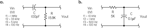
FIGURE 3.81
Answer: (a) f−3dB = 100,097 Hz; f1 = 1 MHz, AdB = −0.043 dB, ϕ = 5.71°; f2 = 33 kHz, AdB = −10.08 dB, ϕ = 71.7°; f3 = 5 kHz, AdB = −26.04 dB, ϕ = 87.1°; f4 = 100 Hz, AdB = −60.00 dB, ϕ = 89.9°.
(b) f−3dB = 318 Hz; f1 = 10 kHz, AdB = −29.95 dB, ϕ = −88.2°; f2 = 1 kHz, AdB = −10.36 dB, ϕ = −72.3°; f3 = 500 Hz, AdB = −5.40 dB, ϕ = −57.5°; f4 = 100 Hz, AdB = −0.41 dB, ϕ = −17.4°.
Problem 7: For the half-wave rectifier supply shown in Fig. 3.82, find the average dc output voltage, the peak-to-peak ripple voltage, the rms ripple voltage, the ripple factor, and percent ripple.
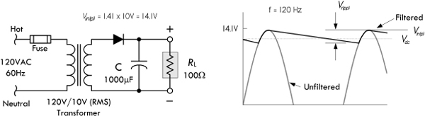
FIGURE 3.82
Answer: Vdc = 12.92 V, Vr(pp) = 2.35 V, Vr(rms) = 0.68 VAC, ripple factor = 0.0526, percent ripple = 5.26%. See Fig. 3.74.
3.7 Inductors
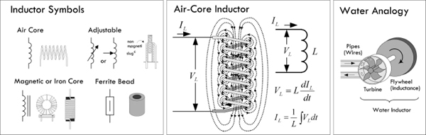
FIGURE 3.83
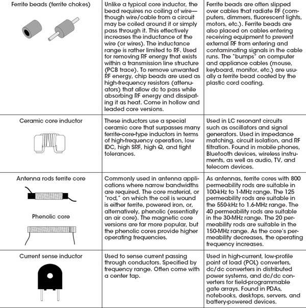
The basic role of an inductor is to prevent any sudden changes in current from flowing through it. (Refer to Sec. 2.24 for the details of how this works.) Under ac conditions, an inductor’s impedance (reactance) increases with frequency; an inductor acts to block high-frequency signals while allowing low-frequency signals to pass through it. By selecting the proper inductance value, it is possible to create high-frequency chokes (e.g., RF/EMI chokes) that, when placed in series with power or signal paths, will prevent RF (radiofrequency) or EMI (electromagnetic interference) from entering into the main circuit, where they could introduce undesired hum and false triggering effects.
Filter networks can be created when inductors are used alongside other components such as resistors and capacitors. For example, Fig. 3.84a and b show low-pass and high-pass filters using an inductor as the reactive element. In the low-pass filter, the inductor “chokes” out the high-frequency components, while in the high-pass filter the inductor passes the low-frequency components to ground—high-frequency components are prevented from taking the same path and follow the signal path. Series-resonant (bandpass) and parallel-resonant (notch) filters are shown in Figs. 3.84c and d. Parallel-resonant filters are used in oscillator circuits to eliminate, from an amplifier, any input any frequencies significantly different from the resonant frequency of the LC filter. Such circuits are often used to generate radiofrequency carrier signals for transmitters. Resonant filters also act as tuned circuits used in radio reception.
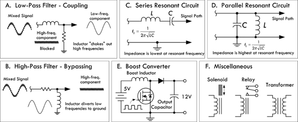
FIGURE 3.84
The energy storage nature of an inductor can be utilized in switching power supplies. For example, in Fig. 3.84e, a step-up switching regulator or “boost converter” is used to increase a 5-V input voltage to a 12-V output voltage. When the control element (transistor) is on, energy is stored in the inductor. The load, isolated by the diode, is supplied by the charge stored in the capacitor. When the control element is off, the energy stored in the inductor is added to the input voltage. At this time, the inductor supplies load current as well as restoring charge to the capacitor. Other converter configurations include step-down and inverting switching regulators.
A heavily wound, iron core inductor can be used as an electromagnet, capable of attracting steel and other ferromagnetic materials. A solenoid is an electromagnet that has a mechanical mechanism that is pulled when the solenoid is energized by current. The movement mechanism may involve latching or unlatching a door, or opening or closing a valve (i.e., a solenoid valve), or making or breaking switch contacts (as in an electrical relay).
Coupled inductors that share magnetic flux linkage are used to create transformers—devices that utilize mutual inductance to step up or step down ac voltages and currents.
The voltage across an inductor is proportional to the rate at which the current changes. The relationship between voltage and current are described by the following equations:
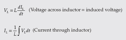
The proportionality constant L is the inductance, which depends on a number of physical parameters, such as coil shape, number of turns, and core makeup. The basic unit of inductance is the henry, abbreviated H. One henry equals an induced voltage of 1 V when the current is varying at a rate of 1 A/s:
Typical values of inductance for commercial inductors vary from a few nanohenrys for small air core inductors to 50 H for large iron core inductors.
3.7.2 Constructing Inductors
Although constructing a capacitor from scratch is rare and usually unnecessary, constructing an inductor from scratch is quite common. Often it is necessary, since specific inductance values may be difficult to find or overly expensive in commercial units. Even stock inductors often require trimming to match an accurately desired value. Figure 3.85 shows some formulas used to construct inductors. Refer to Sec. 2.24 to see example calculations.
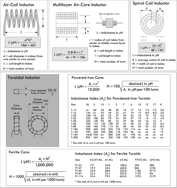
FIGURE 3.85
3.7.3 Inductors in Series and Parallel
When two or more inductors are connected in series, the total inductance is equal to the sum of the individual inductances, provided the coils are sufficiently separated so that coils are not in the magnetic field of one another:
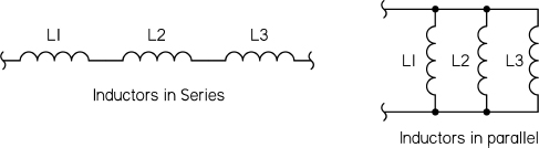
FIGURE 3.86
If inductors are connected in parallel, and if the coils are separated sufficiently, the total inductance is given by:
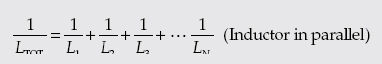
When only two inductors are in parallel, the formula simplifies to LTOT = (L1 × L2)/(L1 + L2). Refer to Sec. 2.24 to see how these formulas were derived.
3.7.4 RL Time Constant
When a resistor is placed in series with an inductor, the resistance controls the rate at which energy is pumped into the magnetic field of an inductor (or pumped back into the circuit when the field collapses). Figure 3.87 shows energizing and deenergizing RL circuits with corresponding current-versus-time response curves.
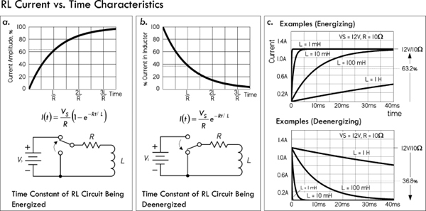
FIGURE 3.87
In the energizing RL circuit, the inductor current and voltage as a function of time after the switch is thrown to the up position is given by the following equation:
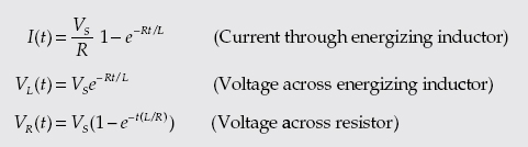
The time in seconds required for current to build up to 63.2 percent of the maximum value is called the time constant τ, which is equal to L/R. After five time constants, the current is considered to have reached its maximum value.
For a deenergizing RL circuit, things are a bit tricky. However, if we assume when we remove the applied voltage that there is no break in the circuit by moving the discharge to the ground, we can apply the following deenergizing equations:
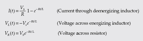
It takes one time constant τ = L/R for the inductor to lose 63.2 percent of its initial current value. After five time constants, the current is considered to have reached its minimum value.
The deenergizing RL circuit requires special attention. In real life, when the current flow through an inductor is suddenly interrupted—say, by flipping a switch—there can be a very large induced voltage generated as the inductor’s magnetic field rapidly collapses. The magnitude of the induced voltage can be so great that “electron pressure” at the switch contacts overcomes the work function of the metal, and a spark may jump between the contacts. Section 2.24 describes inductive spikes in greater detail.
3.7.5 Inductive Reactance
An inductor has a frequency-sensitive impedance, or inductive reactance, that increases with applied frequency. Unlike resistance, the inductive reactance doesn’t dissipate energy in the form of heat, but temporarily stores energy in a magnetic field and later returns it (or reflects it back) to the source. Inductive reactance has units of ohms, and it increases with frequency according to the following equation:
For example, a 1-H coil with an applied frequency of 60 Hz will provide 377 Ω of reactance, while a 10-μH inductor at 20 MHz will provide 1257 Ω of reactance.
Note that the preceding equation is for an ideal inductor. Real inductors have imperfections, such as internal resistance and capacitance that tend to cause the reactance to deviate from the equation, especially at higher frequencies—see Sec. 2.24.
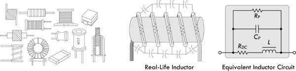
FIGURE 3.88
There are many different kinds of inductors used for various applications. Selecting the right inductor requires understanding the nonideal characteristics of real inductors. Real inductors have imperfections, such as internal resistance and capacitance, that make them operate slightly differently than the ideal equations predict. Some inductors, due to their construction, may have larger resistive or capacitive components inherent in their design that can cause the inductor to act in a nonlinear fashion when approaching certain frequencies. (See Section 2.24 for details.) Other important differences include current-handling capacity, tolerance, maximum inductance and size, quality factor (Q), saturation characteristics, adjustability, radiated electromagnetic interference (EMI), and environmental endurance.
The following provides important inductor specifications that you’ll find listed in manufacturer data sheets.
3.7.7 Inductor Specifications
Inductance (L): The property of an element that tends to oppose any change in the current flowing through it. The inductance depends on core material, core shape, size, and turn count of the coil. The unit of inductance is the henry (H). Most often, inductances are expressed in microhenries (μH).
1 henry (H) = 106 μF
1 millihenry (mH) = 103 μH
1 nanohenry (nH) = 10−3 μH
1 henry (H) = 106 μF
1 millihenry (mH) = 103 μH
1 nanohenry (nH) = 10−3 μH
Inductive tolerance: Inductive tolerance is the allowed amount of variation from the nominal value specified by the manufacturer. Standard inductance tolerances are typically designated by a tolerance letter: F = ±1%, G = ±2%, H = ±3%, J = ±5%, K = ±10%, L = ±15% (some military products L = ±20%), M = ±20%.
Direct current resistance (DCR): The resistance of the inductor winding measured using dc current. The DCR is most often minimized in the design of an inductor and specified as a maximum rating.
Incremental current: The dc bias current flowing through an inductor that causes an inductance drop of 5 percent from the initial zero dc bias inductance value. This current level indicates where the inductance can be expected to drop significantly if the dc bias current is increased further. This applies mostly to ferrite cores rather than to powdered iron. Powdered iron cores exhibit soft saturation characteristics, which means their inductance drop from higher dc levels is much more gradual than that of ferrite cores. The rate at which the inductance will drop is also a function of the core shape.
Maximum dc current (IDC): The level of continuous direct current that can be passed through an inductor with no damage. The dc current level is based on a maximum temperature rise at the maximum rated ambient temperature. For low-frequency currents, the RMS current can be substituted for the dc-rated current.
Saturation current: The dc bias current flowing through an inductor that causes the inductance to drop by a specified amount from the initial zero dc bias inductance value. Common specified inductance drop percentages are 10 percent and 20 percent. It is useful to use the 10 percent inductance drop value for ferrite cores and 20 percent for powdered iron cores in energy storage applications. The cause of the inductance drop due to the dc bias current is related to the magnetic properties of the core. The core, and some of the space around the core, can store only a given amount of magnetic flux density. Beyond the maximum flux density point, the permeability of the core is reduced; thus, the inductance drops. Core saturation does not apply to air core inductors.
Self-resonant frequency (SRF or f0): The frequency at which the inductor’s distributed capacitance resonates with the inductance. At this frequency, the inductance is equal to the capacitance and they cancel each other. As a consequence, at SRF, the inductor acts as a purely resistive high-impedance element. Also at this frequency, the Q value of the inductor is zero. Distributed capacitance is caused by the turns of wire layered on top of each other and around the core. This capacitance is in parallel to the inductance. At frequencies above SRF, the capacitive reactance of the parallel combination will become the dominant component.
Quality factor (Q): The measure of the relative losses in the inductor. Q is defined as the ratio of inductive reactance to the effective resistance, or XL/RE. Since both XL and RE are functions of frequency, the test frequency must be given when specifying Q. As the self-resonant frequency, Q is zero since the inductance is zero at that point. Ideally, Q = XL/RDC = 2πf L/RDC.
Inductance temperature coefficient: The change in inductance per unit temperature change. Measured under zero bias condition and expressed in parts per million (ppm).
Resistance temperature coefficient: The change in dc wire resistance per unit temperature change. Measured low dc bias (<1 VDC) and expressed in parts per million (ppm).
Curie temperature (TC): The temperature beyond which the core material loses its magnetic properties.
Magnetic saturation flux density (BSAT): A core parameter that indicates the maximum flux the material can be induced to hold. At this value of flux density, all magnetic domains within the core are magnetized and aligned.
Electromagnetic interference (EMI): For inductors, this refers to the amount of magnetic field radiated away from the inductor into space. The field may cause interference with other magnetically sensitive components and may require consideration in circuit design and layout.
3.7.8 Types of Inductors

FIGURE 3.89
There are many different inductors out there. Some inductors are designed for general-purpose filtering, others for RF/EMI filtering, others for high-current choking, and still others for energy storage (in switching power supplies). Typically, manufacturers break down their inductor stock into the following categories: common-mode, general-purpose, high-current, high-frequency, power, and RF chokes. Fundamental specifications for selection include inductance value, dc-rated current, dc resistance, tolerance, and quality factor (Q). Table 3.8 provides a general overview matching inductance characteristics to specified application.
TABLE 3.8 Overview of Typical Applications for Inductors
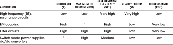
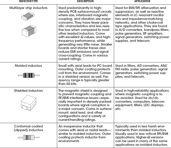
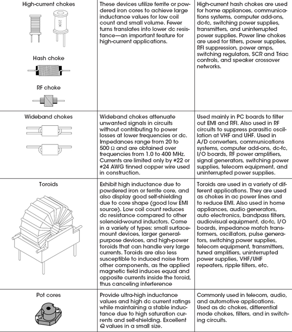
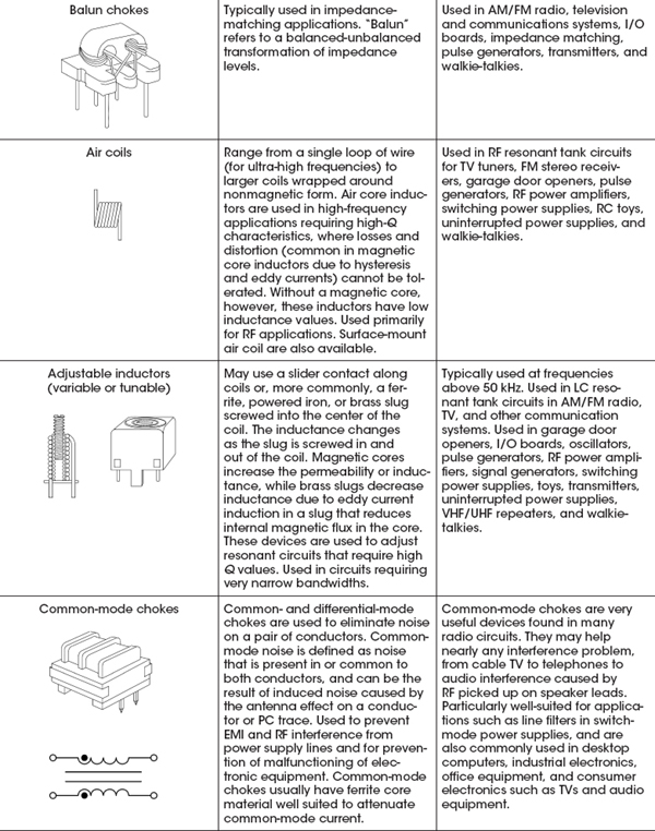
Table 3.9 provides a selection guide to help determine what kind of inductor to use for a particular application. For in-depth details about specific inductors, check out manufacturers’ websites and read through their data sheets. (Some noteworthy manufacturers: API Delevan, Bourns, C&D Technologies, Fastron, KOA, JW Miller Magnetics, muRata, Pulse, TRIAD, TDK, and VISHAY.)
TABLE 3.9 Inductor Selection Guide
3.7.9 Reading Inductor Labels
If you are lucky, the inductance value and tolerance will be printed on your inductor in an easy-to-read format (e.g., 82μH ± 10%). However, many molded and dipped inductors come with a band color code. For smaller surface-mount inductors, a special shorthand printed code provides the inductance value and tolerance—see Fig. 3.90.
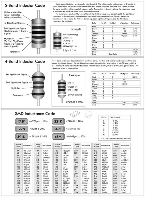
FIGURE 3.90
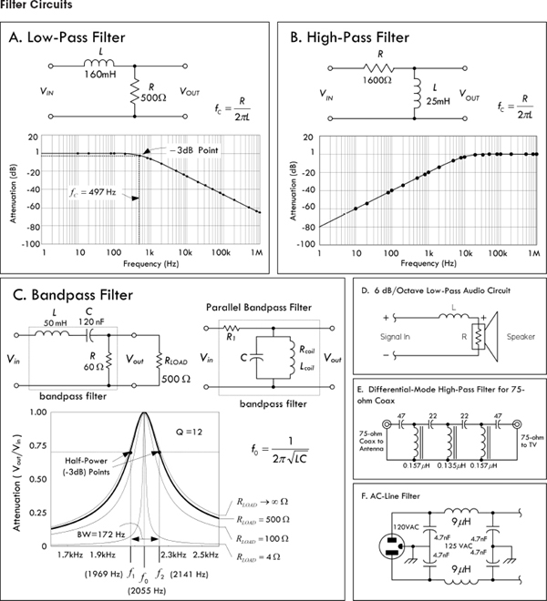
FIGURE 3.91 Filters offer little opposition to certain frequencies while blocking others. In (a), a low-pass filter is constructed using a resistor and inductor. The inductor’s impedance increases with frequency, thus preventing high-frequency signals from passing. In (b), a high-pass filter blocks low frequencies—the inductor acts as a low-impedance path to ground for low-impedance signals. (c) shows a bandpass filter, allowing only a very narrow band of frequencies through. See Chap. 2 for the theory. (d) shows a low-pass filter used with a speaker. (e) shows a differential-mode high-pass filter for 75-Ω co-ax. It rejects high-frequency signals picked up by a TV antenna or that leak into a cable TV system. It is ineffective against common-mode signals, however. (f) shows an ac-line filter used to filter RF energy from power lines.
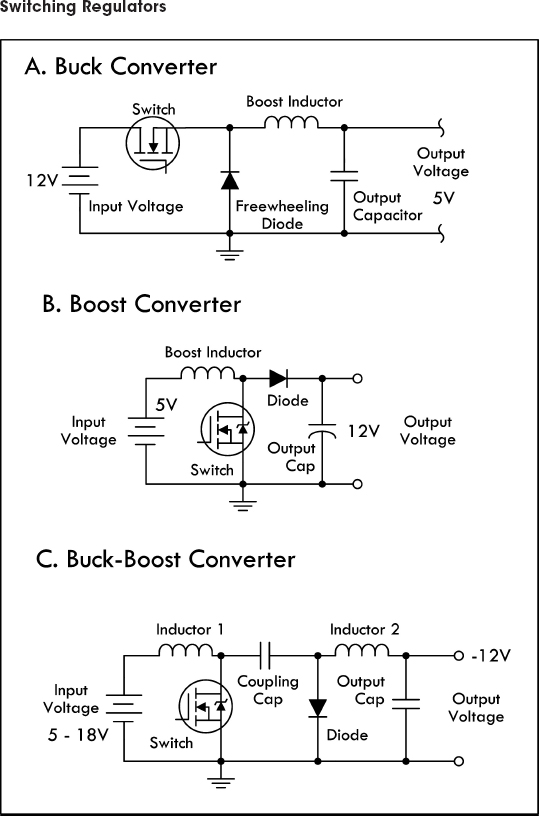
FIGURE 3.92 In switching regulator applications, an inductor is used as an energy storage device, when the semiconductor switch is on, the current in the inductor ramps up and energy is stored. When the switch is turned off, the stored energy is released into the load. Output voltages have a ripple that must be minimized by selecting appropriate inductance and output capacitor values. Figure 3.92a, b, and c shows various switching regulator configurations: buck (lower output voltage), boost (higher output voltage), and buck-boost (opposite polarity). Note that in the boost converter, the boost inductor current does not continuously flow to the load. During the switch “on” period, the inductor current flows to ground and the load current is supplied from the output capacitor.
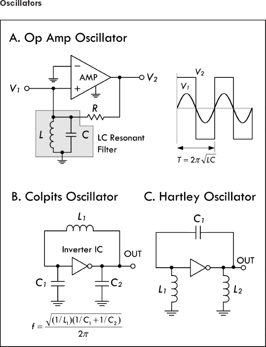
FIGURE 3.93 (a) An amplifier with positive feedback can be made to produce an output even in the absence of any input. Such circuits are called oscillators. In (a), an operational amplifier uses an LC resonant filter that eliminates from the amplifier input any frequencies significantly different from the LC resonant filter’s resonant frequency:  . The amplifier is alternately driven to saturation in the positive and negative direction, so it produces a squarewave at V2. This squarewave has a Fourier component that is fed back to the noninverting input through resistor R in order to keep the oscillation from damping out. A sine wave is generated at V1.
(b) There are two basic types of LC oscillators, Colpits and Hartley. The Colpits uses two capacitors, as shown here. It is generally favored over the Hartley, shown in (c), because of the simplicity of requiring only one inductor, which is usually more expensive and difficult to obtain than capacitors C1 and C2. The frequency of the Colpits oscillator is given by the formula in (b). See Chap. 10 on oscillators for more details.
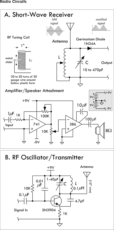
FIGURE 3.94
Here are a few simple radiofrequency circuits that make use of LC resonant filters to tune the circuits.
(a) The simplest radio receiver consists of nothing more than an antenna, a diode (germanium), and a pair of headphones. Such a receiver has no frequency selectivity, however, and will receive several of the strongest AM broadcast stations simultaneously. By adding a variable inductor that forms a resonant LC circuit with the antenna capacitance, a usable radio receiver can be constructed that is capable of tuning in to a number of different stations. (The variable capacitor provides additional tunability.) The encoded audio signal within the AM carrier is demodulated by the diode (the diode generates low-frequency [audio] Fourier components that are absent in the transmitted wave). After passing through the diode, only the positive half of the wave remains. This wave contains low-frequency components in addition to components at the frequency of the carrier wave. With the addition of a low-pass filter, only the low-frequency components remain. The frequency response of headphones and of a human ear will effectively act as a low-pass filter. The demodulated signal can be input into an amplifier to drive a speaker—see amplifier circuit. Real radio AM receivers are much more sophisticated than this, using a superheterodyne design scheme.
(b) A radio transmitter consists of an RF oscillator, one or more amplifier stages, and a modulator. In the simple FM transmitter shown here, the LC resonant filter sets the amplifier oscillatory frequency—the variable capacitor allows for adjustability. Audio signals that enter will be frequency-modulated into the carrier and radiated as radio waves. An FM radio receiver should be able to pick up the circuit signal. A homemade inductor can be made by tightly winding 10 turns of 22-gauge wire around a ¼-in form.
The following are some tips to avoid EMI and EMC problems. Tips include proper design techniques for PCB layout, proper power supply considerations, and effective use of filtering components. (Referenced letters that follow refer to Fig. 3.95.)
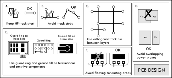
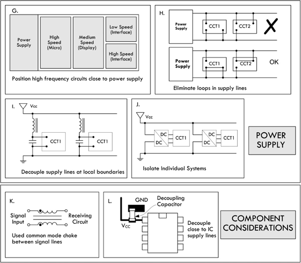
FIGURE 3.95
PCB Design Tips
Avoid slit apertures in PCB layout, such as a ground plane that is divided into two parts. Regions of high impedance are sources of high EMI, so use wide tracks for power lines on the trace sides for increased conduction. Make signal tracks stripline (ground planes above and below) and include ground plane and power plane whenever possible. Keep HF and RF tracks short and lay out the HF tracks first—see (a). In Fig. 3.95. Avoid track stubs, since they cause reflections and harmonics—see (b). Use a surrounding guard ring and ground fill where possible on sensitive components and terminations. A guard ring around trace layers reduces emission out of board. Likewise, connect to ground only at a single point—see (e). Keep separate power planes over a common ground to reduce system noise and power coupling—see (d). Keep track runs as orthogonal as possible between adjacent layers—see (c). Also avoid loop track that acts as a receiving or radiating antenna. Avoid floating conductor areas, since they act as EMI radiators. Connect them to a ground plane otherwise.
Power Supply
Avoid loops in supply lines, as shown in (h). Also decouple supply lines at local boundaries—see (i). Position high-speed circuits closest to the power supply, while placing the slowest section farthest away to reduce power plane transients—see (g). When possible, isolate individual systems on both power supply and signal lines—see (j).
Filtering Components
Position biasing and pull-up/down components close to driver/bias points. Make use of common-mode chokes between current-carrying and signal lines to increase coupling and eliminate stray fields—see (k). Place decoupling capacitors close to chip supply lines to reduce component noise and power line transients—see (l).
These tips were adapted from an Engineering Note, “Electro-Magnetic Interference and Electro-Magnetic Compatibility (EMI/EMC)” written by David B. Fancher, Inductive Products Division, Vishay Dale.
3.8 Transformers
3.8.1 Basic Operations
A basic transformer is a two-port (four-terminal) device capable of transforming an ac input voltage into a higher or lower ac output voltage. Transformers are not designed to raise or lower dc voltages, however, since the conversion mechanism relies on a changing magnetic field generated by a changing current. A typical transformer consists of two or more insulated wire coils that share a common laminated iron core. One of the coils is called the primary (containing NP turns), while the other coil is called the secondary (containing NS turns). A simplistic representation of a transformer is shown in Fig. 3.96, along with its schematic symbol.
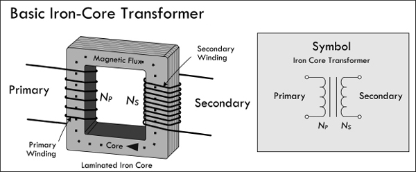
FIGURE 3.96
When an ac voltage is applied across the primary coil of the transformer, an alternating magnetic flux ΦM = ∫(VIN/Np)dt emanates from the primary, propagates through the iron-laminated core, and passes through the secondary coil. (The iron core increases the inductance, and the laminations decrease power-consuming eddy currents.) According to Faraday’s law of induction, the changing magnetic flux induces a voltage of VS = NSdΦM/dt, assuming there is perfect magnetic flux coupling (coefficient of coupling k = 1). Combining the primary flux equation with the secondary induced voltage equation results in the following useful expression:
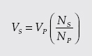
(3.1) Transformer voltage ratio
This equation says that if the number of turns in the primary coil is larger than the number of turns in the secondary coil, the secondary voltage will be smaller than the primary voltage. Conversely, if the number of turns in the primary coil is less than the number of turns in the secondary, the secondary voltage will be larger than the primary.
When a source voltage is applied across a transformer’s primary terminals while the secondary terminals are open-circuited (see Fig. 3.97), the source treats the transformer as if it were a simple inductor with an impedance of ZP = jωLP = ωL ∠ 90°, where LP represents the inductance of the primary coil. This means that the primary current will lag the voltage (source voltage) by 90°, and the primary current will be equal to VP/ZP, according to Ohm’s law. At the same time, a voltage of (NS/NP) VP will be present across the secondary and will be in phase with the primary voltage or 180° out of phase, depending on the secondary coil winding direction or depending on which secondary coil end you choose as a reference (more on this in a moment).
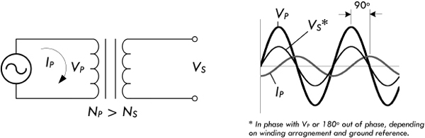
FIGURE 3.97
When there is no load attached to the secondary of a transformer, the current within the primary is called the magnetizing current of the transformer. An ideal transformer, with no internal losses, would consume no power, since the current through the primary inductor would be 90° out of phase with the voltage (in P = IV, I is imaginary and the “power” is imaginary or reactive). With no load in the secondary, the only losses in the transformer are associated with those losses in the iron core and losses within the primary coil wire itself.
Example 1: A transformer has a primary of 200 turns and a secondary of 1200 turns. If a 120 VAC is applied to the primary, what voltage appears across the secondary?
Answer: Rearranging Eq. 3.1,
This is an example of a step-up transformer, since the secondary voltage is higher than the primary voltage.
Example 2: Using the same transformer from Example 1, flip it around so the secondary now acts as the primary. What will be the new secondary voltage?
Answer:
This is an example of a step-down transformer, since the secondary voltage is lower than the primary voltage.
As you can see from the previous example, either winding of a transformer can be used as the primary, provided the windings have enough turns (enough inductance) to induce a voltage equal to the applied voltage without requiring an excessive current. The windings must also have insulation with a voltage rating sufficient for the voltage present.
Now let’s take a look at what happens when you attach a load to the secondary, as shown in Fig. 3.98.
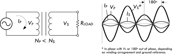
FIGURE 3.98
When a load is attached to the secondary, the secondary current sets up a magnetic field that opposes the field set up by the primary current. For the induced voltage in the primary to equal the applied voltage, the original field must be maintained. The primary must draw enough additional current to set up a field exactly equal and opposite to the field set up by the secondary current. At this point, for practical purposes, we assume that the entire primary current is a result of the secondary load. (This is close to true, since the magnetizing current will be very small in comparison with the primary load current at rated power output.)
Current Ratio
To figure out the relationship between the primary and secondary currents, consider that an ideal transformer is 100 percent efficient (real transformers are around 65 to 99 percent efficient, depending on make), and then infer that all the power dissipated by the load in the secondary will be equal to the power supplied by the primary source. With the help of the generalized power law, we get:
Plugging our transformer voltage equation (3.1) into the VS term, we get:
Eliminating the VP from both sides, we get the following useful current relation:
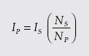
(3.2) Ideal transformer current ratio
Example 3: A transformer with a primary of 180 turns and a secondary with 1260 turns is delivering 0.10 A to a load. What is the primary current?
Answer: Rearranging Eq. 3.2 and solving for the primary current:
Notice from the previous example that even though the secondary voltage is larger than the primary voltage, the secondary current is smaller than the primary current. The secondary current in an ideal transformer is 180° out of phase with the primary current, since the field in the secondary just offsets the field in the primary. The phase relationship between the currents in the windings holds true no matter what the phase difference between the current and the voltage of the secondary. In fact, the phase difference, if any, between voltage and current in the secondary will be reflected back to the primary as an identical phase difference. Note that phase, however, can be selected according to how you pull the secondary out—see the following note.
By now you may be a bit annoyed with the notion of phase. For example, to say that the primary voltage is out of phase with the secondary by 180° is smack in the phase to relativity. Couldn’t you simply wind the secondary winding in a different direction or, more easily, simply reverse the secondary leads to get an output that is within phase? The answer is yes. It is a relativity game with the transformer pins. Figure 3.99 shows two transformers that are identical in every way except for the winding direction of the secondary. The winding A arrangement, when tested with a common ground and oscilloscope, yields in-phase voltages, while the winding in B yields voltage and currents that are 180° out of phase with the primary. To avoid confusion, a convention is used to keep track of the relative polarity between the leads. This convention makes use of what are called phase dots, which are a pair of dots: one placed on the primary side; the other placed on the secondary side. The similar placement of these dots next to the top ends of the primary and secondary windings tells you that whatever instantaneous voltage polarity is seen across the primary winding will be the same as that across the secondary winding. In other words, the phase shift from primary to secondary will be zero degrees. On the other hand, if dots on each winding of the transformer do not match up, the phase shift is 180° between primary and secondary. Of course, the dot convention only tells you which end of each winding is which, relative to the other winding(s). If you want to reverse the phase relationship, all you have to do is swap the winding connections.
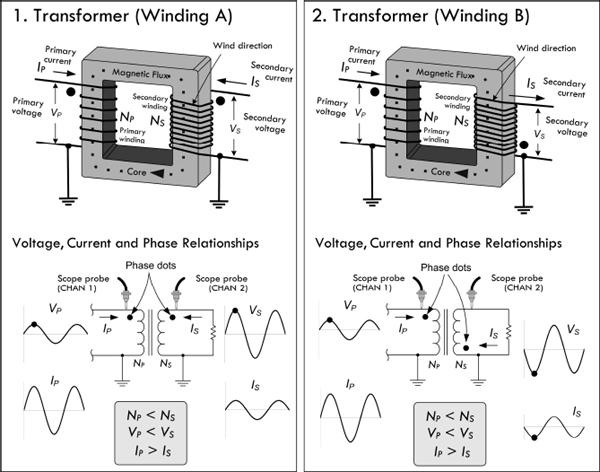
FIGURE 3.99
Power Ratio
A moment ago, when deriving the transformer current equation, we assumed that the transfer of power from primary to secondary was 100 percent efficient. However, it is important to realize that there is always some power loss in the resistance of the coils and in the iron core of the transformer. This means that the power taken from the source is greater than the power used in the secondary. This can be stated by the following expression:
PS = n × PP
(3.3) Efficiency factor
where PS is the power output from the secondary, PP is the power input to primary and n is the efficiency factor. The efficiency n is always less than 1. It is usually expressed as a percentage—for example, 0.75 represents an efficiency of 75 percent.
Example 4: What is the power input to the primary if a transformer has an efficiency of 75 percent and its full load output at the secondary is 100 W?
Answer: Rearranging Eq. 3.3,
Transformers are typically designed to have highest efficiency at the manufacturer’s rated outputs. Above or below the rated output, the efficiency drops. The amount of power a transformer can handle depends on its own losses (heating of wire and core, etc.). Exceeding the rated power of a transformer can lead to wire meltdown or insulation breakdown. Even when the load is purely reactive, the transformer will still be generating heat loss due to internal resistance of the coils and losses in the core. For this reason, manufacturers also specify a maximum volt-amp rating, or VA-rating, that should not be exceeded.
Impedance Ratio
Using ac Ohm’s law, IP = VP/ZP, and assuming an ideal transformer, where power from the primary is 100 percent transferred to secondary, we can come up with an equation relating the primary and secondary impedances:
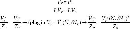
Canceling the primary voltage terms, you get the following useful expression:
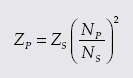
(3.4) Transformer impedance ratio
where ZP is the impedance looking into the primary terminal from the power source, and ZS is the impedance of the load connected to the secondary. Figure 3.100 shows an equivalent circuit.
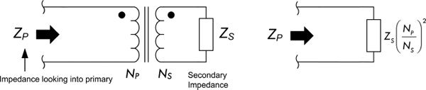
FIGURE 3.100
If the load impedance in the secondary increases, the impedance looking into the primary (from the source’s point of view) will also increase in a manner that is proportional to the ratio of the turns squared.
Example 5: A transformer has a primary with 500 turns and a secondary with 1000 turns. What is the primary impedance if a 2000-Ω load impedance is attached to the secondary?
Answer: Using Eq. 3.4:
As you can see, by selecting the proper turns ratio, the impedance of a fixed load can be transformed to any desired value (ideally). If transformer losses can be neglected, the transformed (reflected) impedance has the same phase angle as the actual load impedance. Hence, if the load is purely resistive, the load presented by the primary to the power source will also be pure resistance. If the load impedance is complex (e.g., inductance and capacitance are thrown in so that load current and voltage are out of phase with each other), then the primary voltage and current will show the same phase angle.
In electronics, there are many instances where circuits require a specific load resistance (or impedance) for optimum performance. The impedance of the actual load dissipating power may differ widely from the impedance of the source. In this case, a transformer can be used to change the actual load into an impedance of desired value. This is referred to as impedance matching. We can rearrange Eq. 3.4 and get:
(3.5)
where NP/NS is the required turns ratio—primary to secondary, ZP is the primary impedance required, and ZS is the impedance of the load connected to the secondary.
Example 6: An amplifier circuit requires a 500-Ω load for optimum performance, but is to be connected to an 8.0-Ω speaker. What turns ratio, primary to secondary, is required in the coupling transformer?
Answer:
Hence, the primary must have eight times as many turns as the secondary.
Knowing what to set the primary count at depends on low internal losses and leakage current and making sure that the primary has enough inductance to operate with low magnetizing current at the voltage applied to the primary.
Example 7: What are the load impedances “seen” by the voltage sources in Fig. 3.101?

FIGURE 3.101
Answer: (a) 30 Ω, (b) 120 Ω, (c) 8 Ω.
Example 8: If a step-up transformer has a turns ratio of 1:3, what are the voltage ratio, current ratio, and impedance ratio? Assume ratios are given in the form “primary: secondary.”
Answer: Voltage ratio is 1:3, current ratio is 3:1, impedance ratio is 1:9.
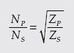
Transformer Gear Analogy
It is often helpful to think of transformers as gearboxes. For example, in the gearbox analogy in Fig. 3.102, the primary winding is analogous to the input shaft (where the motor is attached) and the secondary winding is analogous to the output shaft. Current is equivalent to shaft speed (rmp) and voltage is equivalent to torque. In a gearbox, mechanical power (speed multiplied by torque) is constant (neglecting losses) and is equivalent to electrical power (voltage times current), which is also constant. The gear ratio is equivalent to the transformer step-up or step-down ratio. A step-up transformer acts like a reduction gear (in which mechanical power is transferred from a small, rapidly rotating gear to a large, slowly rotating gear): it trades current (speed) for voltage (torque), by transferring power from a primary coil to a secondary coil having more turns. A step-down transformer acts similarly to a multiplier gear (in which mechanical power is transferred from a large gear to a small gear): it trades voltage (torque) for current (speed), by transferring power from a primary coil to a secondary coil having fewer turns.
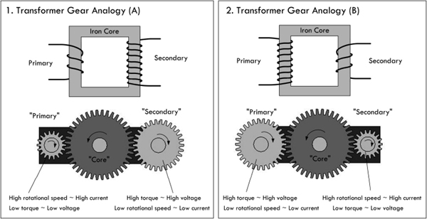
FIGURE 3.102
Center-Tap Transformers
Rarely do you see transformers in the real world with just four leads—two for the primary and two for the secondary. Many commercial transformers employ center taps. A center tap is simply an electrical connection that is made somewhere between the two ends of a transformer winding. By using a center tap, it is possible to utilize only a fraction of the winding voltage. For example, in Fig. 3.103, a transformer’s secondary is center-tapped midway between its winding, yielding two output voltages VS1 and VS2. If we place a ground reference on the center tap (it is treated now as a common), we see the voltages in terms of phase, as shown in the example circuit in Fig. 3.103. In this case, the two secondary voltages are equal because we assumed that the number of turns on either end of the center tap were the same. In general, the secondary voltages are determined by the turns ratio.
FIGURE 3.103
Center taps can be placed on both the primary side and the secondary side, with multiple taps on either side. For example, a typical power transformer has several secondary windings, each providing a different voltage. Figure 3.104 shows a schematic of a typical power supply transformer. It is possible to join pins with a jumper to get the desired voltage ratios across other pins. Manufacturers will provide you with the voltages between the various tap points, usually specifying CT as the center-tap voltage. Center taps provide flexibility in design and allow varying outputs, which you implement by incorporating switches, for example. We’ll see how a center-tap transformer is used to split incoming 240 VAC for the main into two 120-VAC legs within the circuit breaker of your house, and we’ll also discover how full-wave center-tap rectifier circuits are used in building dc power supplies.

FIGURE 3.104
Real Transformer Characteristics
A perfect or ideal transformer has a primary-to-secondary coupling coefficient of 1. This means that both coils link with all the magnetic flux lines, so that the voltage induced per turn is the same for both coils. This also means that the induced voltage per turn is the same for both primary and secondary coils. Iron core transformers operating at low frequencies come close to being ideal. However, due to various imperfections, such as eddy current, hysteresis losses, internal coil resistance, and skin effects at higher frequencies, this isn’t quite true.
In real transformers, not all of the magnetic flux is common to both windings. Flux not associated with linkage is referred to as leakage flux and is responsible for a voltage of self-induction. There are small amounts of leakage inductance associated with both windings of a transformer. Leakage inductance acts in exactly the same manner as an equivalent amount of ordinary inductance inserted in series with the circuit. The reactance associated with leakage inductance is referred to as leakage reactance, which varies with transformer build and frequency. Figure 3.105 shows a real-life model of a transformer including leakage reactances for both primary and secondary coils, namely, XL1 and XL2. When current flows through a leakage reactance, there is an associated voltage drop. The voltage drop becomes greater with increasing current and increases as more power is taken from the secondary.
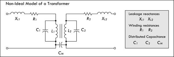
FIGURE 3.105
The internal resistances of a transformer’s windings R1 and R2 also result in voltage drop when there is current flow. Although these voltage drops are not in phase with those caused by leakage reactance, together they result in a lower secondary voltage under load than is indicated by the transformer turns ratio formula.
Another nonideal characteristic of transformers is stray capacitance. An electric field exists between any two points having a different voltage. When current flows through a coil, each turn has a slightly different voltage than its adjacent turns. This results in capacitance between turns and is modeled by C1 and C2 in Fig. 3.105. A mutual capacitance CM also exists between the primary and secondary windings for the same reason. It is also possible for transformer windings to exhibit capacitance relative to nearby metal, such as a chassis, shield, or even the core itself.
Stray capacitance tends to have little influence in power and audio transformers, but becomes influential as the frequencies increase. In RF applications where transformers are used, the stray capacitance can resonate with either the leakage reactance or, at lower frequencies, the winding reactances, especially under very light or zero-ohm loads. In the frequency region around resonance, transformers do not exhibit behavior as described by the previous transformer equations.
Iron core transformers also experience losses with hysteresis and eddy current, as was discussed in Sec. 2.24. These losses, which add to the required magnetizing current, are equivalent to adding a resistance in parallel to R1 in Fig. 3.105.
TRANSFORMER PRECAUTIONS
There are three basic rules to observe when using a transformer. First, never apply a voltage that is greatly in excess of the transformer winding ratings. Second, never allow a significant direct current to flow through any winding not designed to handle it. Third, don’t operate the transformer at a frequency outside the range specified by the manufacturer. Applying a voltage of, say, 120 VAC to a secondary in hopes of achieving 1200 VAC at the primary is a bad idea—expect smoke and combustion, accompanied by insulation failure. Similar results can be expected with excessive dc current through the primary. In terms of frequency, a 60-Hz transformer driven at 20 Hz will draw too much magnetizing current and will run dangerously hot.
3.8.2 Transformer Construction
Cores
Transformers used for power and audio frequencies have cores made of many thin laminations of silicon steel. The laminations reduce eddy currents, as discussed in Sec. 2.24. A typical laminated core is made from E-shaped and I-shaped pieces, sandwiched together, as shown in Fig. 3.106. Transformers made from these cores are therefore often referred to as EI transformers.
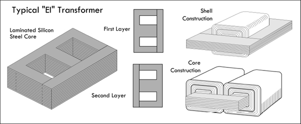
FIGURE 3.106
Two common core shapes in use are shown in Fig. 3.106. In the shell construction, both the primary and the secondary windings are wound around the same inner leg, while in the core construction, primary and secondary windings are wound on separate legs. The core construction is often implemented to minimize capacitive effects between primary and secondary windings, or when one winding is to be operated at very high voltage. The size, shape, and type of core material, as well as the frequency range, influence the required number of turns in each winding. In most transformers, the coils are wound in layers, with a sheet of special paper insulation placed between each layer. A thicker insulation is used between adjacent coils and between the core and the first coil.
Powdered iron cores, with their low eddy current characteristics, are used in transformers that operate above mains frequencies (60 Hz) up to several kilohertz. These cores have a very high permeability and thus provide decent stepping capability for their size. Transformers that are used in even higher-frequency applications, such as RF, often contain cores made from nonconductive magnetic ceramic materials or ferrites.
A common core shape for powdered iron and ferrite core transformers is the toroid, as shown in Fig. 3.107a. The closed ring shape of the toroid eliminates air gaps inherent in the construction of an EI core. The primary and secondary coils are often wound concentrically to cover the entire surface of the core. Ferrite cores are used at higher frequencies, typically between a few tens of kilohertz to a megahertz. In general, toroidal transformers are more efficient (around 95 percent) than cheaper laminated EI transformers; they are more compact (about half the size), weigh less (about half), have less mechanical hum (making them superior in audio applications), and have lower off-load losses (making them more efficient in standby circuits).
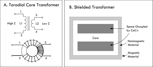
FIGURE 3.107
Shielding
To eliminate mutual capacitance between windings within a transformer, an electrostatic shield is often placed between the windings. Some transformers may incorporate a magnetic shield, as shown in Fig. 3.107b. The magnetic shield helps prevent outside magnetic fields (interference) from inducing currents within the inner windings. The shield also helps prevent the transformer from becoming an interference radiator itself.
For small-power and signal transformers, the windings are made from solid wire copper, insulated typically with enamel; sometimes additional insulation is used for safety. Larger-power transformers may be wound with copper or aluminum wire, or even strip conductors for very heavy current; in some cases multistrand conductors are used to reduce skin effect losses. High-frequency transformers operating in the kilohertz range often have windings made of Litz wire to minimize skin effects. For signal transformers, the windings may be arranged in a way to minimize leakage inductance and stray capacitance in order to improve high-frequency response.
3.8.3 Autotransformers and Variable Transformers
An autotransformer is similar to a standard transformer; however, it uses only one single coil and a center tap (or taps) to make primary and secondary connections. See Fig. 3.108. As with standard transformers, autotransformers can be used to step up or step down voltages, as well as match impedances; however, they will not provide electrical isolation like a standard transformer, since their primary and secondary are on the same coil—there is no electrical isolation between the two coils.
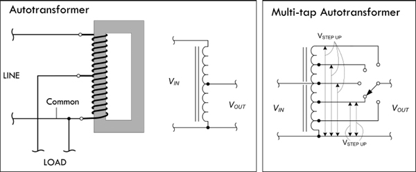
FIGURE 3.108
Although an autotransformer has only one winding, the laws of induction that were used with a standard transformer to step up and step down voltage can be applied just as well. This also applies to principles of current and impedance as a function of the number of winding turns. In Fig. 3.108, the current in the common winding is the difference between the line current (primary current) and the load current (secondary current), since these currents are out of phase. Hence, if the line and load currents are nearly equal, the common section of the winding may be wound with comparatively small wire. The line and load currents will be equal only when the primary (line) and secondary (load) voltages are close in magnitude.
Autotransformers are often used in impedance-matching applications. They are also frequently used for boosting or reducing the power-line voltage by relatively small amounts. Figure 3.108 shows a switch-stepped autotransformer whose output voltage can be set to any number of values determined by the switch contact position.
A variable transformer or Variac (commercial name) is similar to the switch-stepped autotransformer in Fig. 3.108; however, it has a continuous wiper action along a circular coil, as shown in Fig. 3.109. A Variac acts like an adjustable ac voltage source. Its primary is connected to the hot and neutral of the 120-V line voltage, while the secondary leads consist of the neutral and an adjustable wiper that moves along the single core winding.
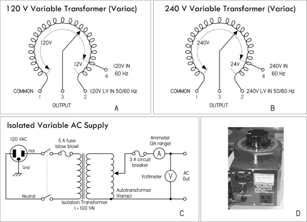
FIGURE 3.109 (a) Nonisolated 120-V Variac whose output voltage is varied by rotating a wiper. (b) Nonisolated 240-V Variac. (c) A homemade variable ac supply with isolation protection provided by means of an isolation transformer. (d) ac power supply that houses an isolation transformer, Variac, switch, fuse, ac outlet, and meter.
Being able to adjust the line voltage is a very useful trick when troubleshooting line-power equipment, where the fuse instantly blows at normal line voltage. Even without a fuse blowing, troubleshooting at around 85 V may reduce the fault current.
It is important to note that a Variac by itself does not provide isolation protection like a standard transformer, since the primary and secondary shared a common winding. It is therefore important, if you plan to work on ungrounded, “hot chassis” equipment, that you place an isolation transformer before the Variac—never after it. If you don’t, shock hazards await. Figure 3.109c shows a schematic of such an arrangement. It includes a switch and fuse protection, as well as current and voltage meters, all of which create an adjustable, fully isolated ac power source.
To avoid the hassle of cascading a Variac and isolation transformer together, simply get an ac power supply that houses both elements together in one package—see Fig. 3.109d.
Boosting and Bucking
We just saw how autotransformers are used in applications requiring a slight boost or reduction in voltage to a load. It is possible to accomplish the same effect by using a normal (isolated) transformer with just the right primary/secondary turns ratio. There is still another alternative—use a step-down configuration with secondary winding connected in a series-aiding (“boosting”) or series-opposing (“bucking”) configuration, as shown in Fig. 3.110.
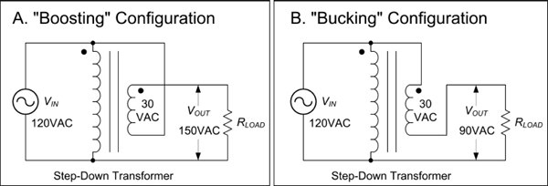
FIGURE 3.110
In the boosting configuration, the secondary coil’s polarity is oriented so that its voltage directly adds to the primary voltage. In the bucking configuration, the secondary coil’s polarity is oriented so that its voltage directly subtracts from the primary voltage. An autotransformer does the same job as the boosting and bucking functions displayed here, but using only a single winding, making it cheaper and lighter to manufacture.
3.8.4 Circuit Isolation and the Isolation Transformer
Transformers perform an important role in isolating one circuit from another. Figure 3.111 shows an example application that uses a transformer to isolate a load connected to an ac outlet. In this application, there is no need to step up or step down the voltage, so the transformer has a 1:1 winding ratio. Such a transformer is referred to as an isolation transformer. In Fig. 3.111, a mains isolation transformer is used to isolate a load from the source, as well as provide ground fault protection. An isolation transformer should be used whenever you work on nongrounded equipment, with no input isolation, such as switch-mode power supplies.
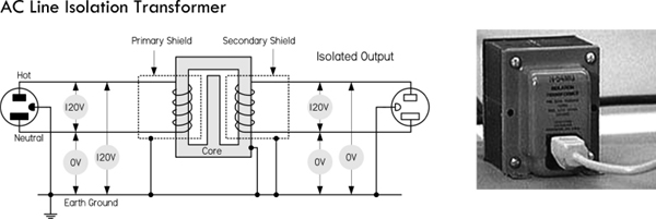
FIGURE 3.111
In your home wiring, the neutral (white) and the ground (green) connections are tied together at the main junction box, so they are basically at the same potential—0 V, or earth ground. If you accidentally touch the hot wire while being in contact with a grounded object, current will pass through your body and give you a potentially fatal shock. With an isolation transformer, the secondary winding leads act as a 120-V source and return, similar to the mains’ hot and neutral, but with an important difference. Neither the secondary source nor return runs are tied to earth ground! This means that if you touch the secondary source or return while being in contact with a grounded object, no current will flow through your body. Current only wants to pass between the secondary source and return runs. (Note that all transformers provide isolation, not just line isolation transformers. Therefore, equipment with input power transformers already have basic isolation protection built in. Isolation transformers used for laboratory work are explained in greater detail in Sec. 7.5.12.)
Isolation transformers are also typically constructed with two isolated Faraday shields between the primary and secondary windings. The use of the two shields diverts high-frequency noise, which would normally be coupled across the transformer to ground. Increasing the separation between the two Faraday shields minimizes the capacitance between the two and, hence, the coupling of noise between the two. Therefore, the isolation transformer acts to clean up line power noise before being delivered to a circuit.
3.8.5 Various Standard and Specialized Transformers

These transformers are used primarily to reduce line voltage. They come in a variety of different shapes, sizes, and primary and secondary winding ratios. They often come with taps and multiple secondary windings. Color-coded wires are frequently used to indicate primary and secondary leads (e.g., black wires for primary, green for secondary, and yellow for tap lead is one possibility). Other transformers use pins for primary, secondary, and tapped leads, allowing them to be mounted on a PC board. You can also find transformers in wall-mount packages that plug directly into an ac outlet, with screw-in terminals as secondary and tapped leads.
FIGURE 3.112
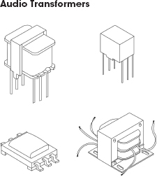
Audio transformers are used primarily to match impedances between audio devices (e.g., between microphone and amplifier or amplifier and speaker), though they can be implemented in other ways as well. They work best at audio frequencies from 20 Hz to 20 kHz. Outside this range they will reduce or block signals. They come in a variety of shapes and sizes and typically contain a center tap in both the primary and secondary windings. Some come with color-coded wires to specify leads, while other audio transformers have pinlike terminals that can be mounted on PC boards. Spec tables provide dc resistance values for primary and secondary windings to help you select the appropriate transformer for the particular matching application. Besides performing simple impedance matching, audio transformers can be used to step up or step down a signal voltage, convert a circuit from unbalanced to balanced and vice versa, block dc current in a circuit while allowing ac current to flow, and provide basic isolation between one device and another. Note that audio transformers have a maximum input level that cannot be exceeded without causing distortion. Also, audio transformers cannot step up a signal by more than about 25 dB when used in typical audio circuits. Because of this, an audio transformer cannot be substituted for a microphone preamp. If more than 25 dB of gain is required, an active preamp must be used instead of a transformer.
FIGURE 3.113
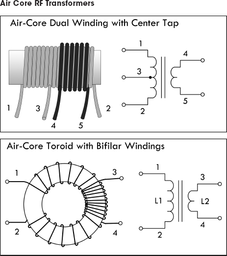
Air core transformers are special devices used in radio-frequency circuits. (They are used for RF coupling, such as antenna tuning and impedance matching.) Unlike steel or ferrite core transformers, the core is made from a nonmagnetic form, usually a hollow tube of plastic. The degree of coupling between windings in an air core transformer is much less than that of a steel core transformer; however, there are no losses associated with eddy currents, hysteresis, saturation, and so on, as is the case with magnetic cores. This becomes critically important in RF applications—at high frequencies, steel core transformers experience significant losses. Toroidal air core transformers aren’t common nowadays, except in VHF (very high frequency) work. Today, special coupling networks and RF powdered-iron and ferrite toroids have generally replaced air cores, except in situations where the circuit handles very high power or the coils must be very temperature stable.
FIGURE 3.114
3.8.6 Transformer Applications
There are three principal uses for transformers: to transform voltages and currents from one level to another, to physically isolate the primary circuit from the secondary, and to transform circuit impedances from one level to another. Here are some examples in action.
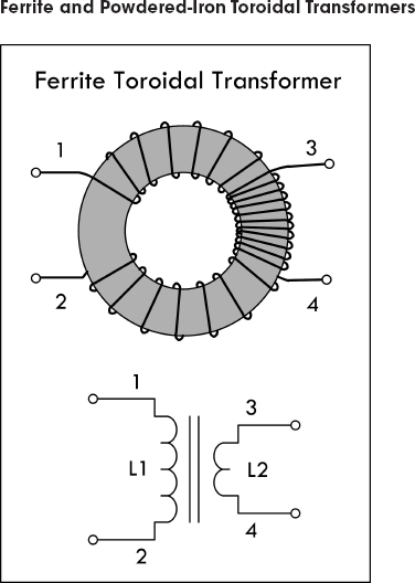
Toroidal ferrite and powdered-iron transformers are used from a few hundred hertz well into the UHF spectrum. The principal advantage of this type of core is self-shielding and low losses due to eddy currents. The permeability/size ratio is also very large, making them compact devices requiring fewer coil turns than traditional transformers. The most common ferrite toroid transformer is the conventional broadband transformer. Broadband transformers provide dc isolation between the primary and secondary circuits. The primary of a step-down impedance transformer is wound to occupy the entire core, with the secondary wound over the primary, as shown in Fig. 3.115. This style of transformer is frequently used in impedance matching. In standard broadcast radio receivers, these transformers operate in a frequency range from 530 to 1550 kHz. In shortwave receivers, RF transformers are subjected to frequencies up to about 20 MHz; in radar, it approaches upward of 200 MHz.
FIGURE 3.115
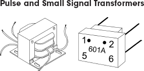
Pulse transformers are special transformers optimized for transmitting rectangular electrical pulses—ones with fast rise and fall times and constant amplitude. A small signal transformer is a small version of a pulse transformer. These devices are used in digital logic and telecom circuits, often for matching logic drivers to transmission lines. Medium-size power versions are used in power-control circuits such as camera flash controllers, while larger-power versions are used in electrical power distribution to interface low-voltage control circuitry with high-voltage power semiconductive gates, such as TRIACs, IGBTs, thyristors, and MOSFETs. Special high-voltage pulse transformers are used to generate high-power pulses for radar, particle accelerators, or other pulsed power applications.
To minimize pulse shape distortion, a pulse transformer requires very low leakage inductance and distributed capacitance, and a high open-circuit inductance. Low coupling capacitance is also important in power-pulse transformer applications to protect circuitry on the primary side from high-power transients created by load.
To minimize pulse shape distortion, a pulse transformer requires very low leakage inductance and distributed capacitance, and a high open-circuit inductance. Low coupling capacitance is also important in power-pulse transformer applications to protect circuitry on the primary side from high-power transients created by load.
FIGURE 3.116

Current transformers are special devices used primarily to measure larger currents that would be too dangerous to measure with an ammeter. They are designed to provide a current in their secondary that is proportional to the current flowing in the primary. A typical current transformer resembles a toroidal core inductor with many secondary windings. The primary coil consists of simply passing a single cable-to-be-measured (insulated) through the center of the toroid. The output current through the secondary is many times smaller than the actual current through the cable (primary). These transformers are specified by their input and output current ratio (400:5, 2000:5, etc.). Current transformers designed for electrical supply applications are designed to drive 5-A (full-scale) meters. There are also wideband current transformers used to measure high-frequency waveforms and pulsed currents.
FIGURE 3.117
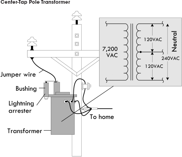
FIGURE 3.118 In the United States, main power lines carry ac voltages upward of several thousand volts. A center-tap pole transformer is used to step down the line voltage to 240 V. The tap then acts to break this voltage up into 120-V portions. Small appliances, such as TVs, lights, and hair dryers can use either the top line and the neutral line or the bottom line and the neutral line. (The neutral is grounded to a ground rod through a link between neutral and ground buses in the breaker box.) Larger appliances, such as stoves, refrigerators, and clothes dryers often make use of the 240-V terminals and often use the neutral terminal as well. See App. A for more on power distribution and home wiring.
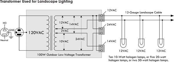
FIGURE 3.119 Here a step-down low-voltage transformer is used to drive quartz halogen landscape lamps. The lamps in this case don’t care if the voltage is ac since the frequency (60 Hz) is too fast for there to be any noticeable variation in luminous output. Most commercial transformers used for landscape wiring, or for driving solenoid-powered sprinkler systems, will come with multiple outputs. This transformer provides 12-V, 24-V, and 14-V outputs. The 14-V output may be used to drive 12-V lamps if there is an anticipated voltage drop along long cable runs; the 24-V output may be used to drive 24-V devices. Note that the total load should not consume more power than the transformer’s rated output capacity. For example, this 100-W transformer should not be used to drive more than, say, ten 10-watt lamps or five 20-watt lamps. Exceeding this will result in lamp dimming.
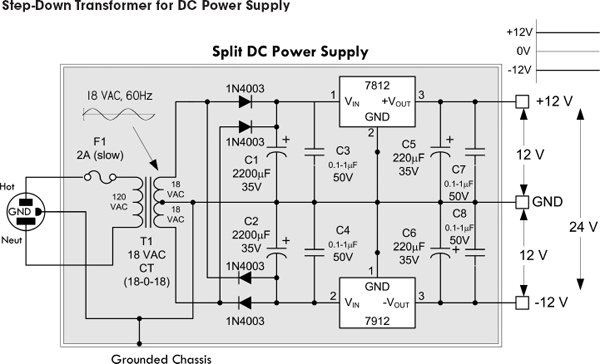
FIGURE 3.120 Transformers are essential ingredients in power supply design. Here a 120-V to 18V-0-18V center-tap transformer is used to create a split ±12-V dc power supply. The transformer acts to reduce the voltage to 18 VAC across each coil end and the center tap. The rectifier section built from diodes acts to eliminate negative swings in the upper positive section and eliminate positive swings in the lower section. Capacitors are thrown in to remove the pulsating dc and make the voltages appear dc. The regulators are used to set the dc voltages to exactly +12 V and −12 V. See Chap. 11 on power supplies for more details.
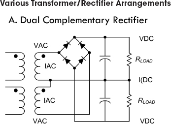
There are various ways in which to create dc power supplies. Figure 3.121 shows the four basic schemes used. Each scheme has its pros and cons, which are briefly described here and in greater detail in the sections on diodes and power supply in chapters to come.
(a) Dual complementary rectifier: Very efficient and best choice for two balanced outputs with a common return. The output windings are bifilar wound for precisely matched series resistances, coupling, and capacitance.
(a) Dual complementary rectifier: Very efficient and best choice for two balanced outputs with a common return. The output windings are bifilar wound for precisely matched series resistances, coupling, and capacitance.
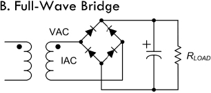
(b) Full-wave bridge: Most efficient use of transformer’s secondary winding. Best for high-voltage outputs.
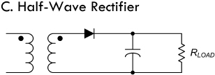
(c) Half-wave rectifier: This design should be avoided for power supply design, as it is an inefficient use of the transformer. This arrangement causes the core to become polarized and to saturate in one direction.

(d) Full-wave center tap: While more efficient than the half-wave rectifier circuit, the full wave does not make full use of secondaries, but is good for high-current, low-voltage applications, as there is only one diode drop per positive half cycle.
FIGURE 3.121
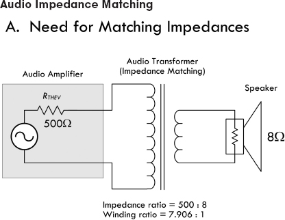
(a) Maximum power is transferred to a load if the load impedance is equal to the Thevenin impedance of the network supplying power. To supply maximum power transfer from the audio amplifier with an output impedance of 500 Ω to an 8-Ω speaker, we must properly match the load impedance with that of the output impedance (or Thevenin impedance) of the source. If we were not to match impedance and attempt to drive the 8-Ω speaker directly, the impedance mismatch would result in very poor (low peak power) performance. Also, the amplifier would dissipate considerable power in the form of heat as it tries to drive the low-impedance speaker.
When going from a high-impedance (high-voltage, low-current) source to a low-impedance (low-voltage, high-current) load, we need to use a step-down transformer. To determine the turns ratio required, we refer back to Eq. 5:
When going from a high-impedance (high-voltage, low-current) source to a low-impedance (low-voltage, high-current) load, we need to use a step-down transformer. To determine the turns ratio required, we refer back to Eq. 5:
In other words, the required winding ratio is 7.906:1. With such a transformer in place, the speaker will load the amplifier to just the right degree, drawing power at the correct voltage and current levels for the most efficient power transfer to load.
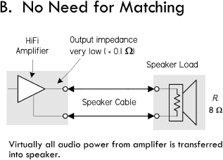
(b) Note that most transistor or IC hi-fi amplifier and speaker systems have amplifiers with output impedances much lower than the speaker impedance. A typical speaker impedance is 8 Ω, for example, but most hi-fi amplifiers have an output impedance of 0.1 Ω or less. This not only ensures that most of the audio energy is transferred to the speaker, but also that the amplifier’s low output impedance provides good electrical damping for the speaker’s moving voice coil—giving higher fidelity.
Older valve amplifiers needed a different form of impedance matching, because output valves generally had fairly fixed and relatively high output impedance so they couldn’t deliver audio energy efficiently into the low load impedance of a typical speaker. So an output transformer had to be used to produce a closer impedance match. The transformer stepped up the impedance of the speaker, so that it gave the output valve an effective load of a few thousand ohms; this was at least comparable to the valve’s own output impedance, so only a small amount of energy was wasted as heat in the valve.
Older valve amplifiers needed a different form of impedance matching, because output valves generally had fairly fixed and relatively high output impedance so they couldn’t deliver audio energy efficiently into the low load impedance of a typical speaker. So an output transformer had to be used to produce a closer impedance match. The transformer stepped up the impedance of the speaker, so that it gave the output valve an effective load of a few thousand ohms; this was at least comparable to the valve’s own output impedance, so only a small amount of energy was wasted as heat in the valve.
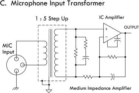
(c) The only area in audio where impedance matching (of a different kind) tends to be important is with transducers such as microphones, turntable pickups, and tape heads. Here, the transducer often needs to be provided with particular load impedance, but not in order to maximize power or signal transfer.
The diagram in (c) shows a typical matching arrangement for a microphone connected through a matching transformer to an input stage (unity gain stage) of an audio amplifier IC.
The diagram in (c) shows a typical matching arrangement for a microphone connected through a matching transformer to an input stage (unity gain stage) of an audio amplifier IC.
FIGURE 3.122
Fuses and circuit breakers are devices designed to protect circuits from excessive current flows, which are often a result of large currents that result from shorts or sudden power surges. A fuse contains a narrow strip of metal that is designed to melt when current flow exceeds its current rating, thereby interrupting power to the circuit. Once a fuse blows (wire melts), it must be replaced with a new one. A circuit breaker is a mechanical device that can be reset after it “blows.” It contains a spring-loaded contact that is latched into position against another contact. When the current flow exceeds a breaker’s current rating, a bimetallic strip heats up and bends. As the strip bends, it “trips” the latch, and the spring pulls the contacts apart. To reset the breaker, a button or rockerlike switch is pressed to compress the spring and reset the latch.
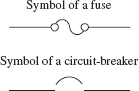
FIGURE 3.123
In homes, fuses/circuit breakers are used to prevent the wires within the walls from melting under excessive current flow (typically upwards of 15 A); they are not designed to protect devices, such as dc power supplies, oscilloscopes, and other line-powered devices, from damage. For example, if an important current-limiting component within a test instrument (powered from the main line) shorts out, or if it is connected to an extremely large test current, the circuit within the device may be flooded with, say, 10 A instead of 0.1 A. According to P = I2R, the increase in wattage will be 10,000 times larger, and as a result, the components within the circuit will fry. As the circuit is melting away, no help will come from the main 15-A breaker—the surge in current through the device may be large, but not large enough to trip the breaker. For this reason, it is essential that each individual device contain its own properly rated fuse.
Fuses come in fast-action (quick-blow) and time-lag (slow-blow) types. A fast-acting fuse will turn off with just a brief surge in current, whereas a time-lag fuse will take a while longer (a second or so). Time-lag fuses are used in circuits that have large turn-on currents, such as motor circuits, and other inductive-type circuits.
In practice, a fuse’s current rating should be around 50 percent larger than the expected nominal current rating. The additional leeway allows for unexpected, slight variations in current and also provides compensation for fuses whose current ratings decrease as they age.
Fuses and breakers that are used with 120-V ac line power must be placed in the hot line (black wire in the United States) and must be placed before the device they are designed to protect. If a fuse or circuit breaker is placed in the neutral line (white wire), the full line-voltage will be present at the input, even if the fuse/circuit breaker blows. Circuit breakers that are used to protect 240-V ac appliances (e.g., stoves, clothes dryers) have fuses on all three input wires (both the hot wires and the neutral wire) (see Fig. 3.124). Power distribution and home wiring are covered in detail in App. A.
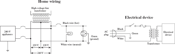
FIGURE 3.124
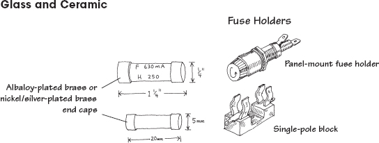
These are made by encapsulating a current-sensitive wire or ceramic element within a glass cylinder. Each end of the cylinder contains a metal cap that acts as a contact lead. Fuses may be fast-acting or time-lagging. They are used in instruments, electric circuits, and small appliances. Typical cylinders come in ¼ × 1¼ in or 5 × 20 mm sizes. Current ratings range from around ¼ to 20 A, with voltage ratings of 32, 125, and 250 V.
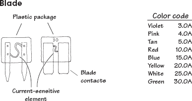
These are fast-acting fuses with bladelike contacts. They are easy to install and remove from their sockets. Current ratings range from 3 to 30 A, with voltage ratings of 32 and 36 V. They are color-coded according to current rating and are used primarily as automobile fuses.
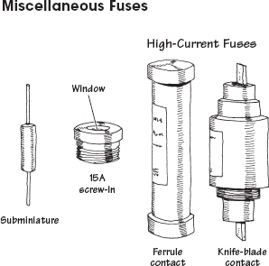
Other types of fuses include subminiature fuses and high-current screw-in and cartridge fuses. Subminiature fuses are small devices with two wire leads that can be mounted on PC boards. Current ratings range from 0.05 to 10 A. They are used primarily in miniature circuits. Cartridge fuses are designed to handle very large currents. They are typically used as main power shutoffs and in subpanels for 240-V applications such as electric dryers and air conditioners. Cartridge fuses are wrapped in paper, like shotgun shells, and come with either ferrule or knife-blade contacts. Ferrule-contact fuses protect from up to 60 A, while knife-blade contact fuses are rated at 60 A or higher.
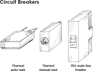
These come in both rocker and push-button forms. Some have manual resets, while others have thermally actuated resets (they reset themselves as they cool down). Main-line circuit breakers are rated at 15 to 20 A. Smaller circuit breakers may be rated as low as 1 A.
FIGURE 3.125
..................Content has been hidden....................
You can't read the all page of ebook, please click here login for view all page.