
9
Audio Hacks
In this chapter, you will look at audio electronics and find out how to make and amplify sounds so you can drive a loudspeaker.
You will also discover how to hack an FM transmitter intended for use with MP3 players in the car, so that it works as a surveillance bug.
First though, we will look at the more mundane topic of audio leads, how to use them, mend them, and make your own.
Hacking Audio Leads
Ready-to-use audio leads are pretty cheap to buy unless you go for the high-end connectors. Sometimes though, if you need a lead in a hurry, or an unusual lead, it helps to know how to wire one up from parts in your junk box or from connectors you have bought.
Many items of consumer electronics are supplied with a range of leads, and you do not always need them for use with the item you bought. Keep them in your junk box since you never know when you might need to make some kind of lead.
Figure 9-1 shows a selection of audio plugs, some designed to have leads soldered to them, and others that have plastic moldings around the lead and cable, which cannot be soldered to. Plugs with plastic moldings around them are still useful, however. It just means you will have to cut and strip the wire that leads to the plug rather than solder it to the plug itself.
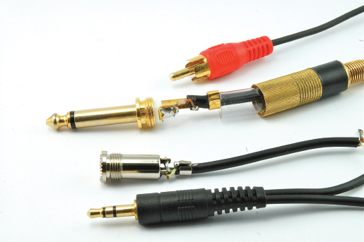
FIGURE 9-1 A variety of audio plugs
General Principals
Audio leads carry audio signals, often on their way to an amplifier, and the last thing you want is for them to pick up electrical noise that will affect the quality of the sound. For this reason, audio leads are normally screened (see Figure 9-2).
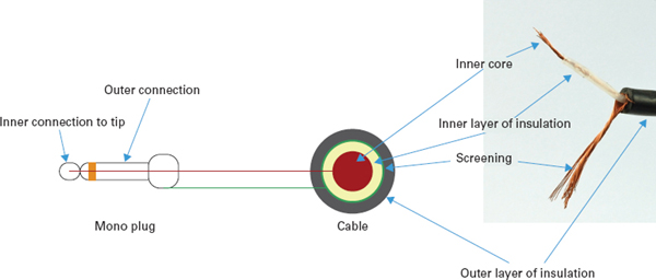
FIGURE 9-2 A screened audio lead
The audio signal itself (or two audio signals for stereo) is carried on insulated multi-core wires that are then enclosed in an outer conductive sheath of screening wire that carries the ground connection.
The exception to this is for leads to loudspeakers. These are not screened because the signal has been amplified to such a degree that any noise the speaker cables might pick up would be undetectable.
Soldering Audio Connectors
Stripping audio connectors is made more difficult by the fact that there is more than one layer of insulation. It is very easy to accidentally cut through the shielding. Nicking the outer insulation all around before stripping it will usually help with this problem.
Figure 9-3 shows the sequence involved in soldering a screened lead to a 6.3mm jack plug of the sort often used to connect an electric guitar to its amplifier.
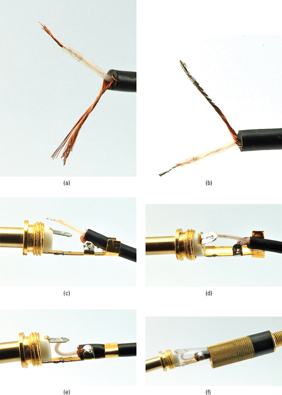
FIGURE 9-3 Soldering a screened lead to a 6.3mm jack plug
The first step is to strip off the outer insulation about 20mm (a bit less than an inch) from the end of the lead and tease the shielding wires around to one side of the lead and twist them together. Strip about 5mm of insulation off the inner core insulation (Figure 9-3a). Then, tin both bare ends (Figure 9-3b).
The jack plug has two solder tags: one for the outer part of the plug and one connected to the tip. Both will usually have holes in them. Figure 9-3c shows the screening trimmed to a shorter length and pushed through the hole ready to solder. Once the screening is soldered into place, solder the inner core to the solder tag for the tip (Figure 9-3d).
These wires are quite delicate, so make sure the inner core wire has some extra length (as shown in Figure 9-3e) so that if the plug flexes, it will not break the connection. Notice that the strain relief tabs at the end of the plug have been pinched around the outer insulation. Finally, the plug will often have a plastic sleeve that protects the connections. Slide this over the connections and then screw in the plug casing.
 |
If there is a plug on the other end of the lead, remember to push the new plug enclosure and plastic sleeve onto the lead BEFORE you solder the second plug on, otherwise you will end up having to unsolder everything to put it on. The author has made this mistake more times than he cares to admit. |
Converting a Stereo Signal to Mono
Stereo audio is made up of two slightly different audio signals that give the stereo effect when played through two separate speakers. Sometimes, you have a stereo output that you want to input to a single channel (mono) amplifier.
You could use just one of the channels of the stereo signal (say, the left channel), but then you will lose whatever is on the right channel. So a better way of converting stereo to mono is to use a pair of resistors to mix the two channels into one (Figure 9-4).
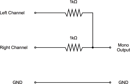
FIGURE 9-4 Mixing stereo to mono
Looking at the schematic of Figure 9-4, you could be forgiven for thinking all you need to do is connect the left and right channels to each other directly. This is not a good idea, because if the signals are very different, there is the potential for a damaging current to flow from one to the other.
As an example, we could use the mono 6.3mm jack we just soldered leads to, and combine it with a pair of resistors and a stereo 3.5mm jack plug so we could, for example, plug an MP3 player into a guitar practice amplifier.
Figure 9-5 shows the steps involved in this. To make it easier to photograph, the author’s lead is made very short. You will probably want to make yours longer. This is not a problem, unless you plan to make it longer than a few yards or meters.
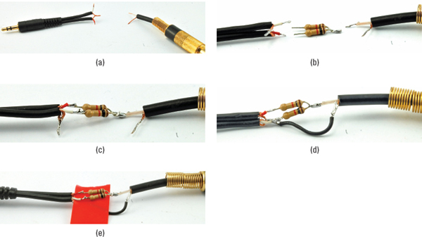
FIGURE 9-5 Making a lead
The 3.5mm plug is of the plastic molded variety, reclaimed from some unwanted lead. The first step is to strip both leads (Figure 9-5a). Note that the stereo plug has two screened connections in one twin cable. The screened ground connections of both channels of the stereo plug can be twisted together.
Tin the ends of all the leads, and then solder the resistors together, as shown in Figure 9-5b.
Next, solder the stereo and mono leads to the resistors, as shown in Figure 9-5c, and cut and tin a short length of wire to bridge the ground connections. Solder it into place (Figure 9-5d) and then wrap everything in insulating tape, taking care to put tape in between any places where wires could short together (Figure 9-5e).
How to Use a Microphone Module
Microphones (mics) respond to sound waves, but sound waves are just small changes in air pressure, so it is not surprising that the signal you get from a mic is usually very faint. It requires amplification to bring it up to a useable level.
While it is perfectly possible to make a little amplifier to boost the signal from your mic, you can also buy a mic module that has an amplifier built in. Figure 9-6 shows such a module.
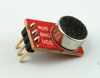
FIGURE 9-6 A microphone module
The mic module just requires a supply voltage between 2.7V and 5.5V. This makes it ideal for interfacing with an Arduino.
In Chapter 11, you will find out a bit more about oscilloscopes. But for now, here is a sneak preview of what an oscilloscope will display (see Figure 9-7) when connected to the mic module while a constant tone is being generated and the module is supplied with 5V.
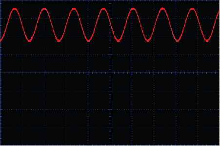
FIGURE 9-7 The output of the microphone module
The oscilloscope is displaying the sound. In this case, a constant and rather irritating tone of 7.4 kHz. The horizontal axis is time, and each blue square represents 100 microseconds. The vertical axis is the voltage and each square is 1V. The output of the mic module is a voltage that varies very quickly between about 1.8V and 3.5V. If you draw a horizontal line straight down the middle of the waveform, it would be at about 2.5V. This is halfway between 0V and 5V. So if there is no sound at all, there will just be a flat line at 2.5V, and as the sound gets louder, the waveform will swing further and further either way. It will not, however, go higher than 5V or lower than 0V. Instead, the signal will clip and become distorted.
The mic module shown is sold by SparkFun (BOB-09964). The schematic for this, along with all its design files have been made public. Figure 9-8 shows a schematic for a typical microphone pre-amp.
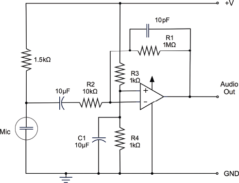
FIGURE 9-8 The schematic diagram for a mic module
The chip at the center of this design has a similar circuit symbol to the comparator you used in the “How to Detect Noxious Gas” section at the beginning of Chapter 8. However, it is not a comparator; it is an amplifier IC of a type known as an “operational amplifier” (or “op amp” for short).
Whereas a comparator turns its output on when the “+” input is higher than the “–” input, an op amp amplifies the difference between the “+” and “–” inputs. Left to its own devices, it amplifies this by a factor of millions. This means that the tiniest signal or noise on the input would be turned into meaningless thrashing of the output from 0 to 5V. To tame the op amp and reduce its amplification factor (called “gain”), something called “feedback” is used.
The trick is to take a portion of the output and feed it into the negative input of the op amp. This reduces the gain to an amount determined by the ratio of R1 to R2, shown in Figure 9-8. In this case, R1 is 1MΩ and R2 is 10kΩ, so the gain is 1,000,000 / 10,000 or 100.
The signal from the microphone is being amplified by a factor of 100. This shows just how weak the signal is in the first place.
The “+” input to the op amp is held halfway between GND and 5V (2.5V) by using R3 and R4 as a voltage divider. C1 helps to keep this constant.
From the schematic, you can see how you could build the module yourself on, say, stripboard. Op amps like the one used (which is a surface-mounted device) are also available in the eight-pin DIP form. However, a module like this will save you a lot of effort and may even turn out cheaper than buying and building a module from scratch.
I realize this is a rather cursory introduction to op amps. These are very useful devices, but unfortunately require more space to explain fully than this book can accommodate. You will find good information on op amps at the Wikipedia site, as well as in books with a more theoretical bent like Practical Electronics for Inventors, Third Edition, by Paul Sherz and Simon Monk, which has a chapter devoted exclusively to op amps.
In the next section, we will combine this module with a hacked FM transmitter of the sort used to let you play your MP3 player through your car radio, thus creating an audio “bug.”
How to Make an FM Bug
To make an FM transmitter that will broadcast sound picked up from a microphone to a nearby FM radio receiver would require a lot of effort. We are hackers, so we are going to cheat and take apart an FM transmitter and wire it up to a mic module. Figure 9-9 shows the end result of this hack.
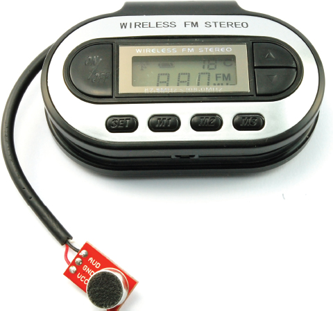
FIGURE 9-9 An FM radio bug
You Will Need
To build the bug, you will need the following.
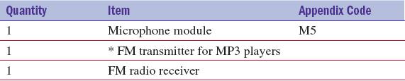
* For suitable FM transmitters, try searching on eBay using the search terms “fm transmitter mp3 car.” Expect to pay about USD 5 and look for the most basic of models. You do not need remote control or an SD card interface. You just want something that has an audio input lead, and for simplicity purposes runs on two AA or AAA batteries (3V).
Construction
This is a very easy project to make. Figure 9-10 shows the schematic diagram for the bug.
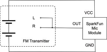
FIGURE 9-10 Schematic diagram for the radio bug
The 3V battery of the FM transmitter is used to provide power to the mic module, and the single output of the mic module is connected to both the left and right inputs of the stereo FM transmitter.
Figure 9-11 shows how the FM transmitter is modified to connect the mic module to it.
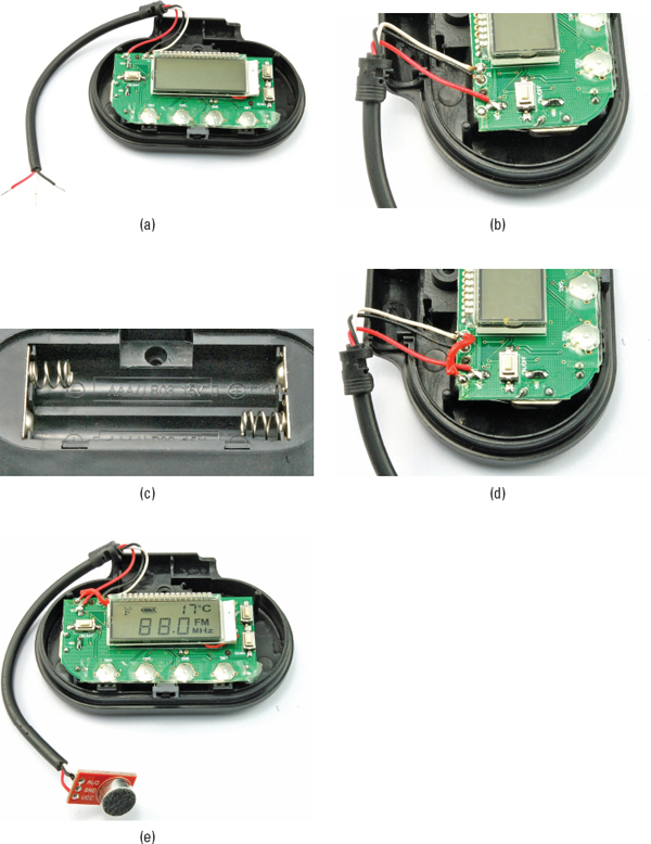
FIGURE 9-11 Modding the FM transmitter
The first step is to unscrew any screws that hold the case together and pull it apart. Then, chop off the plug, leaving most of the lead in place since the lead often doubles as an antenna in these devices. Strip and tin the three wires inside the lead (Figure 9-11a).
Looking at the three wires, in Figure 9-11a, the red wire is the right signal, the white the left, and the black ground. This is a common convention, but if you are not sure it applies to your transmitter, you can check by stripping the wires on the plug end of the lead you cut off and using the continuity setting on your multimeter to see which lead is connected to what on the plug. The farthest tip and next ring should be the left and right signals, and the metal nearest the plastic should be the ground connection.
We are going to leave the ground and left connections as they are, but disconnect the wire and connect it to the 3V connection of the battery (Figure 9-11b). In this transmitter, the positive terminal of the battery box underneath the PCB is soldered to the top surface of the PCB.
To find the positive connection, look carefully at the battery box. In Figure 9-11c, you can see that the metal piece on the left of the figure links the negative of the top cell to the positive of the bottom cell. The 3V connection will therefore be the top right connection of the battery box, so trace where this comes out on the top of the PCB. If it is attached by wires, then find an appropriate place for the red wire of the audio jack lead to be joined to it.
Referring back to the schematic diagram of Figure 9-10, we need to make a little wire just to link the left and right channels (Figure 9-11d). When all the changes are complete, it should look like Figure 9-11e.
Testing
Note that the on/off button of the transmitter will have no effect on the power going to the mic module. So to fully turn off the bug, remove the batteries.
To test the module out, set the frequency of the FM transmitter to one not occupied by a radio station and then set the radio receiver to the same frequency. You may well hear the howl of feedback through the radio. To prevent that, take the radio receiver to a different room. You should find that you can hear what is happening in the room with the bug in it pretty clearly.
Selecting Loudspeakers
Loudspeakers have remained largely unchanged in design since the early days of radio. Figure 9-12 shows how a loudspeaker works.
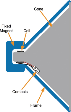
FIGURE 9-12 How a loudspeaker works
The cone (often still made of paper) has a light coil around the end that sits within a fixed magnet attached to the frame of the loudspeaker. When the coil is driven by an amplified audio signal, it moves toward and away from the magnet in time with the audio. This creates pressure waves in the air, producing a sound.
Electronically speaking, a loudspeaker just looks like a coil. When you buy a speaker like this, it will have a number of ohms associated with it. Most speakers are 8Ω, but you can also commonly find 4Ω and 60Ω speakers. If you measure the resistance of the coil of an 8Ω speaker, you should find that it is indeed about 8Ω.
Another figure that is normally stated with the speaker is the power. This specifies how hard the loudspeaker can be driven before the coil will get too hot and burn out. For a small loudspeaker such as one you might put in a small radio receiver, values of 250 mW and up are not untypical. As you progress toward the kind of speakers you would use with a hi-fi set, you will see figures in the tens of watts, or even hundreds of watts.
It is very hard to build speakers that can cover the whole range of audio frequencies, which is generally standardized as 20 Hz up to 20 kHz. So you will often find hi-fi speakers that group a number of speakers into a single box. This might be a “woofer” (for low frequencies) and a “tweeter” (for high frequencies). Because woofers cannot keep up with the high frequencies, a module called a “crossover network” is used to separate the low and high frequencies and drive the two types of speakers separately. Sometimes this is taken a step further and three drive units are used: one for bass, one for mid-range tones, and a tweeter for high frequencies.
The human ear can pick out the direction of a high-frequency sound very easily. If you hear a bird tweeting in a tree, you will probably be able to look straight at it without having to think about where it is. The same is not true of low frequencies. For this reason, surround-sound systems often have a single low-frequency “woofer” and a number of other speakers that handle midrange and higher frequencies. This makes life easier, because bass speakers have to be much larger than higher-frequency units in order to push large amounts of air about relatively slowly to produce bass sounds.
How to Make a 1-Watt Audio Amplifier
Building a small amplifier to drive a loudspeaker is made easier by an IC like the TDA7052, which contains pretty much all the components you need, on a chip costing less than $1. In this section, you will make a little amplifier module on stripboard (Figure 9-13).
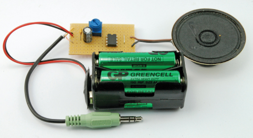
FIGURE 9-13 A 1-watt amplifier module
An alternative to making your own amplifier is to buy a ready-made module. You will find these available for a wide range of different powers and in mono and stereo configurations. eBay is a good source for such modules, as are SparkFun (BOB-11044) and Adafruit (product ID 987). These modules often use an advanced type of design called “class-D,” which is far more efficient in its use of energy than the module we are going to build.
Figure 9-14 shows the typical schematic for a TDA7052 amplifier.
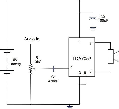
FIGURE 9-14 A typical TDA7052 amplifier schematic
R1 acts as a volume control, reducing the signal before amplification.
C1 is used to pass the audio signal on to the input to the amplifier IC without passing on any bias voltage that the signal may have from the audio device producing the signal. For this reason, when you use a capacitor like this, it is called a coupling capacitor.
C2 is used to provide a reservoir of charge that can be drawn on quickly by the amplifier when it needs it for very rapid changes in the power supplied to the speaker. This capacitor should be positioned close to the IC.
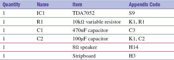
You Will Need
To build the amplifier module, you will need the following.
Construction
Figure 9-15 shows the stripboard layout for the amplifier module. If you have not used stripboard before, read through the section titled “How to Use Stripboard (LED Flasher)” in Chapter 4.
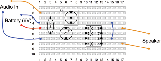
FIGURE 9-15 The stripboard layout for an amplifier module
To build the module, follow the steps shown in Figure 9-16.

FIGURE 9-16 Building the audio amplifier module
First, cut the stripboard to size and make the three cuts in the tracks using a drill bit (Figure 9-16a).
The next step is to solder the link into place, and then the IC, C1, C2, and R1 in that order (Figure 9-16b). It is easiest to solder the components that are lowest to the board first.
Attach leads to the speaker (Figure 9-16c) and finally attach the battery clip and a lead ending in a 3.5mm stereo jack plug (Figure 9-16d). Note that only one channel of the audio lead is used. If you want to use both left and right channels, you should use a pair of resistors (see the section “Hacking Audio Leads” at the beginning of this chapter).
Testing
You can try the amplifier out by plugging it into an MP3 player, or, if you have an Android phone or an iPhone, download a signal generator app like the one shown in Figure 9-17. There are a number of such apps, many of them free, including this one for Android from RadonSoft.
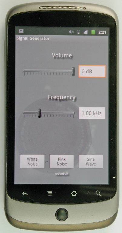
FIGURE 9-17 A signal generator app
With this, you can play a tone at a frequency you select. By noting when the volume of the speaker starts to drop off, you can work out the useful frequency range of your amplifier module.
How to Generate Tones with a 555 Timer
Back in Chapter 4, you used a 555 timer to blink a pair of LEDs. In this section, we will see how to use a 555 timer IC oscillating at much higher frequencies to generate audio tones.
The pitch will be controlled using a light-dependent resistor (LDR) so that as you wave your hand over the light sensor, the pitch will change in a theremin-like manner.
Figure 9-18 shows the tone generator built onto breadboard.
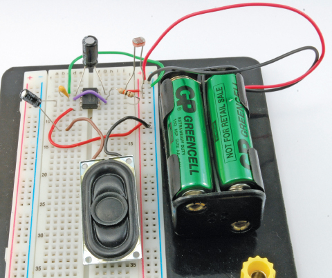
FIGURE 9-18 Generating tones with a 555 timer IC
Figure 9-19 shows the schematic diagram for the tone generator.
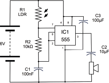
FIGURE 9-19 Schematic diagram for a 555 tone generator
This is similar to the design of the LED flasher in Chapter 4. In this case, instead of two fixed resistors and a capacitor setting the frequency, R1 is the LDR, whose resistance will vary between about 1kΩ and 4kΩ depending on the light falling on it. We need a much higher frequency than our LED flashing circuit—in fact, if we aim for a maximum frequency of around 1 kHz, we need a frequency of about 1000 times what we had before.
The 555 timer oscillates at a frequency determined by the formula:
frequency = 1.44 / ((R1 + 2 * R2) * C)
where the units of R1, R2, and C1 are in O and F.
So, if we use a 100nF capacitor for C1, and R2 is 10kΩ, and R1 (the LDR) has a minimum frequency of 1kΩ, then we can expect a frequency of:
1.44 / ((1000 + 20000) * 0.0000001) = 686 Hz
If the LDR’s resistance increases to 4kΩ then the frequency will drop to:
1.44 / ((4000 + 20000) * 0.0000001) = 320 Hz
To calculate the frequency and when deciding what values of R1, R2, and C1 to use, there are online calculators like this one at www.bowdenshobbycircuits.info/555.htm that will calculate the frequency for you.
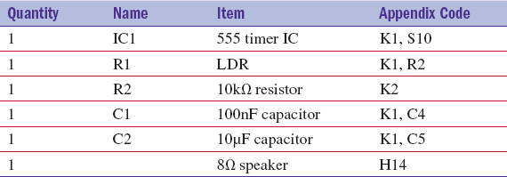
You Will Need
To build the amplifier module, you will need the following.
Construction
Figure 9-20 shows the breadboard layout for the tone generator.
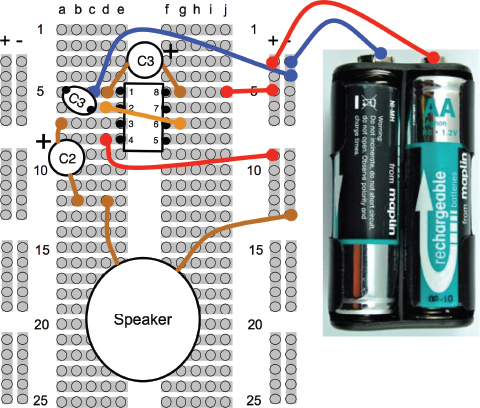
FIGURE 9-20 A signal generator app
It would be quite straightforward to build this design onto stripboard. The stripboard layout in the section “How to Use Stripboard (LED Flasher)” in Chapter 4 would be a good starting point.
How to Make a USB Music Controller
Music software like Ableton Live™ is designed to allow USB controllers that emulate a keyboard to control virtual musical instruments and do all kinds of exciting things. You can use the USB keyboard emulation features of the Arduino Leonardo with an accelerometer so that tilting the board produces a key press of a number between 0 and 8, with 4 being pressed if the board is level, 0 if tilted almost vertically to the right, and 8 being pressed when it is tilted the other way.
The only hardware on the Arduino is the accelerometer (Figure 9-21).
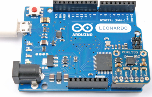
FIGURE 9-21 A USB music controller
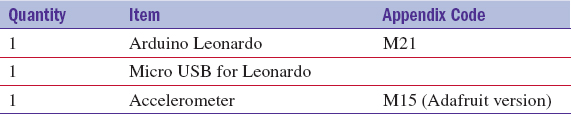
You Will Need
To build this controller, you will need the following items.
Construction
There is actually very little to construct in this project. The schematic is actually the same as in the section titled “How to Use an Accelerometer” in Chapter 8. The Freetronics accelerator will also work, but you will need to change the pin assignments before attaching the accelerometer.
Software
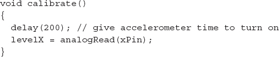
The software for the music controller combines code for sensing the angle of tilt on the X-axis with emulating a keyboard press.
The first step is to assign the pins to be used. As in the section “How to Use an Accelerometer” in Chapter 8, the accelerometer module is powered from output pins.
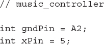
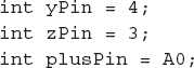
The variable “levelX” is used during calibration and holds the analog value when the accelerometer is flat.
The “oldTilt” variable contains the old value of the tilt of the board, which is a value between 0 and 8, where 4 means level. The old value is remembered, so that a key press is only sent if the tilt angle changes.
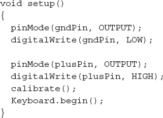
The “setup” function sets the output pins to power the accelerometer, calls “calibrate”, and starts the Leonardo keyboard emulation mode.
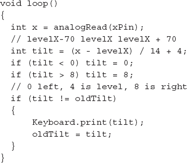
In the main loop, the accelerometer reading is converted to a number between 0 and 8, and if it has changed since the last reading, a key press is generated.
The “calibrate” function takes an initial reading of the acceleration on the X-axis, after waiting 200 milliseconds for the accelerometer to turn on properly.
How to Make a Software VU Meter
The mic module you used in the section “How to Make an FM Bug” is also perfectly suited for use with microcontrollers like the Arduino. Figure 9-22 shows the module with pins attached to it and pushed into the analog connector strip of the Arduino.
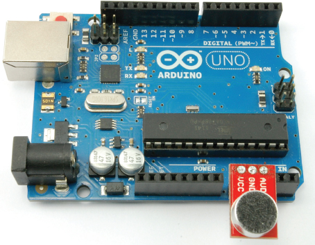
FIGURE 9-22 Attaching a mic module to an Arduino
The mic module can be used to measure the sound level and write a number of “*”s to the Serial Monitor to indicate the loudness of the sound (Figure 9-23).
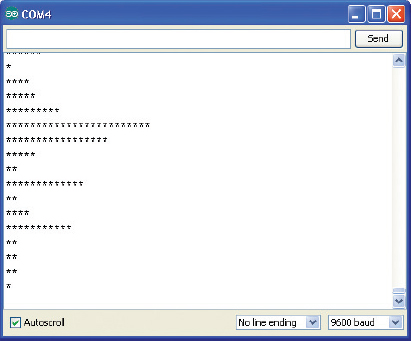
FIGURE 9-23 The Serial Monitor as a VU meter
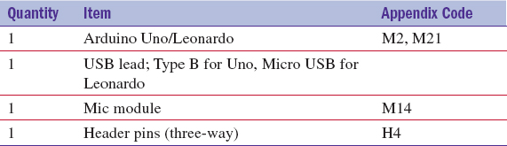
You Will Need
To build this VU meter, you will need the following items.
Construction
Upload the sketch “vu_meter” before attaching the mic module.
Solder the header pins to the module so they will fit into the Arduino sockets A0 to A2 with the microphone facing outward, as shown in Figure 9-22.
Software
The mic module uses very little current, so for convenience we can use A0 and A1 to provide the power to it.
The sketch begins by defining the pins to use and setting them up in the “setup” function. Serial communication is also started here.
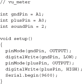
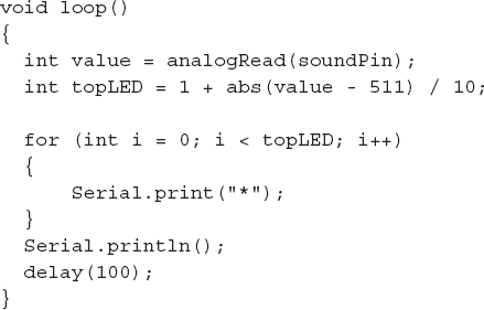
The loop function reads the raw value for the analog input A2. The mic module produces an output of 2.5V when there is no signal, and swings above and blows that with the sound’s waveform. So to find the “loudness” we need to first subtract 511 from the raw value—511 being equivalent to the 2.5V offset in the raw analog reading that spans from 0 to 1023.
The “abs” function makes any negative number positive and then divides the whole result by 10 to give us a number between 0 and 51 and assigns it to the variable “topLED”. We are not actually using LEDs, but you could think of each “*” as being an LED illuminated on a bar graph display.
The “for” loop then prints a number of “*”s equal to the value held in “topLED”. Finally, a new line is printed and we delay for 1/10th of a second.
Summary
In addition to the how-tos just covered, there are lots of audio modules you can make use of. Low-cost stereo power amplifiers are available from eBay and suppliers like SparkFun and Adafruit.
You can also buy ultra-low-cost amplified speakers intended for computers and reuse them in your projects.
..................Content has been hidden....................
You can't read the all page of ebook, please click here login for view all page.