CHAPTER 2
![]()
Components and Schematics
To begin, I will familiarize readers with various components used in electronics. For this chapter, only selected components such as wires, batteries, capacitors, resistors, inductors, and some semiconductors will be explored. Other devices not covered in this chapter will be presented in subsequent chapters. For example, in this chapter, bipolar transistors will be mentioned, but field-effect transistors (FETs) will not be covered here. However, Chapter 6 will cover FETs.
One idea in writing this chapter was to limit the scope to components and to cover the rest of the different parts elsewhere in this book. I did not plan to make this chapter a reference chapter on all types of electronic parts. Closing out this chapter will be a discussion on schematic diagrams.
Wires
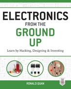
We will start with insulated wires, which are used to connect components and circuits together. Generally, there are two types of insulated wires—multistranded wires and solid single-stranded wires (Figure 2-1).
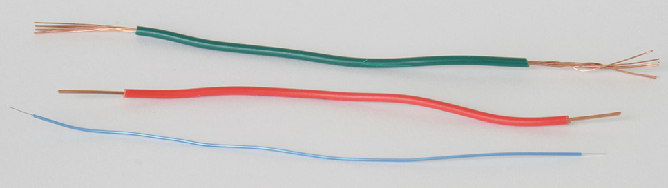
FIGURE 2-1 Stranded wire (top); solid single-stranded wire (middle); and wire-wrap wire (bottom).
Wire thickness in United States is specified by American Wire Gauge (AWG). The lower the AWG number, the thicker is the wire. For typical wires used in electronic circuits, AWG numbers from 20 to 24 are used. Figure 2-1 shows 22 AWG for the top two wires and 26 AWG for the single-strand wire-wrap wire.
Both stranded and solid-strand wires are fine for construction projects. Often it is much easier to use the single-strand wire-wrap wire, as shown in Figure 2-1, because of its small diameter, which allows it to fit into tight places. In “emergencies,” one can use 18- to 24-gauge zip cord or speaker wire (Figure 2-2).
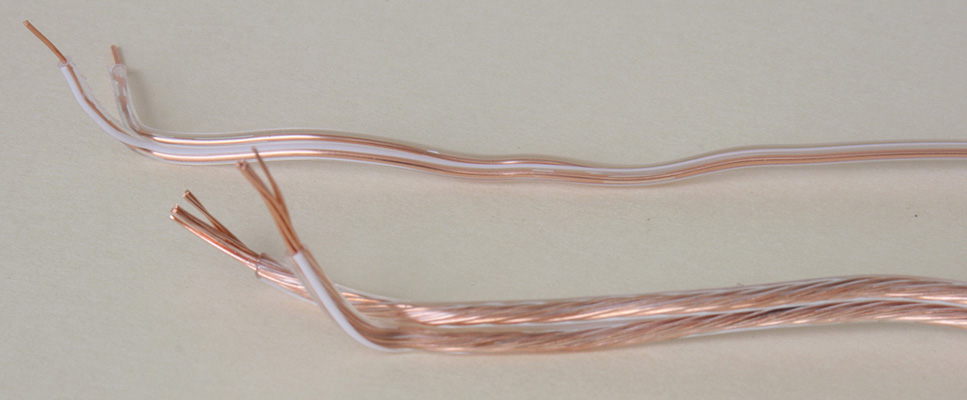
FIGURE 2-2 22 AWG solid-strand speaker wire (top) and 18 AWG stranded speaker wire (bottom).
Note, as shown in Figure 2-2, the zip cord can be separated entirely to provide two separate pieces of wire. Speaker wire can also be used for input and output leads that require hot and ground connections because one wire is normally marked with a stripe. For example, the striped side of a speaker wire can be used as the ground connection. Note that zip cord normally does not have such a marking and can result in a polarity issue, such as crossing the ground lead with the hot lead.
For audio, video, and radio-frequency (RF) signals, coaxial cables are used to shield out extraneous noise (e.g., power-line frequency hum). The outer-shield conductor is normally connected to ground, and the inner wire is the signal or hot lead (Figure 2-3).

FIGURE 2-3 Coaxial cable with an RCA phono connector for audio or video signals.
Wire Tools
When we are constructing circuits, the wires will have to be cut, and a small amount of insulation will have to be removed. Probably the most useful tool for this is the wire-stripping tool for removing insulation from insulated 30 AWG to 20 AWG wires. However, one can also use a wire cutter, diagonal cutter, or a pair of long-nose pliers with a wire-cutting feature. For “emergencies,” a nail clipper or a pair of scissors can be used (Figure 2-4).
FIGURE 2-4 (From left to right) Wire stripper, wire cutter, diagonal cutter, scissors, and nail clipper.
When constructing circuits with electronic components such as resistors, capacitors, transistors, and so on, wire cutters and diagonal cutters are often used to trim off the excess leads after soldering. Typical sizes of wire cutters and diagonal cutters range from 4 inches to 6 inches. Larger cutters may be used, but they may not fit in tight places where the leads have to be trimmed. For bending wires, a pair of long-nose pliers is used (Figure 2-5).

FIGURE 2-5 A pair of long-nose pliers is used for bending leads or wires.
Batteries
Probably the most common battery today is the AA cell. It is used in flashlights, radios, and electronic equipment such as voltmeters and inductance meters. However, for smaller devices, the AAA cell can be found in MP3 audio players, very small radios, and audio recorders. However, one of the most common power sources used for portable test equipment and smoke alarms is the 9-volt rectangular battery. Most batteries will have their positive (+) or negative (–) terminals marked, especially the 9-volt battery. For cylindrical batteries such as AAA, AA, C, and D cells, the positive (+) terminals are at the top and the negative (–) terminals are at the bottom.
Batteries can be categorized as nonrechargeable (e.g., carbon or heavy duty, alkaline, or lithium) and rechargeable [e.g., nickel cadmium, nickel–metal hydride (NiMh), and precharged or low-self-discharged nickel metal hydride] types. Nonrechargeable batteries are not to be installed in any battery charger because they can leak or burst or cause injury. Rechargeable batteries can only be installed in compatible battery chargers, or otherwise, damage can occur (Figures 2-6 and 2-7). Also, for safety reasons, do not install rechargeable batteries in smoke alarms.
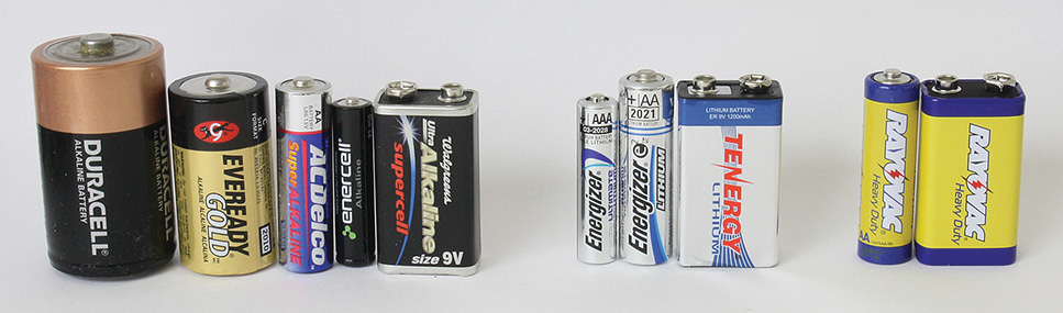
FIGURE 2-6 Five alkaline batteries, three lithium batteries, and two carbon batteries.

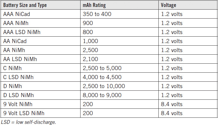
FIGURE 2-7 Regular and low-self-discharge NiMh rechargeable batteries.
It should be noted that as of the year 2014, many of the rechargeable cells are low-self-discharge types that can keep a charge up to one year compared with a couple of months for standard NiMh batteries. My choice is to skip the standard NiMh batteries and get the low-self-discharged types whenever possible. You can usually tell if a battery is a low-self-discharge type by looking for keywords on the battery or package, such as “low self-discharge” or “stays charged up to one year.” In Figure 2-7, the energyOn and Tenergy batteries are low-self-discharge rechargeable batteries. The others are regular NiMh rechargeable batteries that will self-discharge within a few months.
NOTE It is recommended that you buy name-brand (e.g., energyOn, Sanyo, Ray-O-Vac, Energizer, etc.) rechargeable batteries because I found that generic no-name batteries bought on eBay had a much lower milliampere-hour capacity than stated.
See Tables 2-1 and 2-2 for battery capacities of nonrechargeable and rechargeable batteries.
TABLE 2-1 Data for Nonrechargeable or Otherwise Known as Primary Batteries, 2014
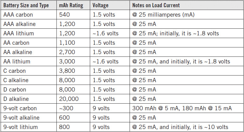
TABLE 2-2 Data for Rechargeable Batteries, 2014
NOTE There is a difference between lithium and lithium-ion batteries. The lithium batteries are not rechargeable. However, in laptop computers and other devices, rechargeable lithium-ion batteries are used.
Both nonrechargeable and rechargeable batteries are rated in milliampere-hour (mAh) capacity that allows one to predict approximately their useful life under a known current drain. For example, a typical two-AAA-cell LED penlight may drain about 150 milliamperes. If a lithium AAA cell with 1,200 mAh is used, we would expect that the LED flashlight will provide about (1,200 mAh/150 mA =) 8 hours of continuous use.
The approximate service life of the battery in hours = yyyy mAh/(load current in milliamps), where yyyy is the rated milliampere-hours of the particular battery. For example, a 1000 mAh battery with a 100 mA load current is expected to last about 1000 mAh/100 mA or 10 hours.
Other types of batteries are coin or button cells used for watches, car keys, LED keychain lights, laser pointers, calculators, and battery backup circuits for computers. Typically, flat coin cells have a voltage of 3 volts and are lithium types, whereas silver oxide or alkaline button cells yield about 1.5 volts. Commonly used 3-volt coin batteries are the CR2016 at 90 mAh, the CR2025 at 163 mAh, and the CR2032 at 240 mAh (Figure 2-8).
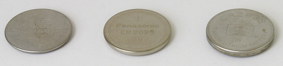
FIGURE 2-8 Coin batteries CR2016, CR2025, and CR2032.
Normally, the polarity of coin or button cells is marked as shown in Figure 2-8, and the positive (+) sign is seen along with the manufacturer’s name and battery number (e.g., CR2025). These batteries are generally used for continuous low-drain service or for intermittent medium-drain applications. For example, many keychain LED lights use two CR2016 batteries that drain at medium currents. However, the users of these keychain LED lights normally operate them for less than a minute at a time. Also, many watches use a single CR2016 battery for continuously draining a low current. The CR2025 battery is used in some electronic car keys. And for battery backup of data in computer motherboards, the CR2032 cell is commonly used.
We have now introduced some of the more commonly used cells and batteries. Obviously, more types are available. One can find more information on various batteries at http://data.energizer.com/SearchResult.aspx.
A “First Hack” on Batteries
Technically speaking, a battery usually includes two or more basic cells. For example, a 9-volt battery is made of six 1.5-volt cells connected in series (Figures 2-9 through 2-11).
FIGURE 2-9 A carbon 9-volt battery “intact” (left) with the battery’s case being removed (right).
FIGURE 2-10 A carbon 9-volt battery with its metal case being removed with a pair of long-nose pliers.
FIGURE 2-11 A carbon 9-volt battery with the outer metal case removed.
In Figure 2-9, an exhausted 9-volt carbon battery is being taken apart by hacking the bottom side. By prying open the seam with a pair of small long-nose pliers, the metal case can be removed. As a word of caution, be careful when taking apart the metal case that you do not get cut. See Figure 2-10.
Finally, Figure 2-11 shows the metal case removed, with the six cells stacked along with the connector. Note that the negative terminal with the wider mouth is connected to the top of the carbon battery and the positive terminal is connected via a flat metal ribbon to the bottom of the battery.
It should be noted that even though the cells of this battery are no longer useful, the 9-volt connector can be salvaged for future experiments.
The Series Circuit and Battery Holders
Batteries are almost always connected in series to generate more voltage, and you see this in 9-volt batteries that are made with six cells connected in series. In a series-connected battery, the cells are connected such that the positive (+) terminal is connected to the next battery’s negative (–) terminal. When batteries are connected correctly in this way, the total voltage across the batteries adds up. That is why two 1.5-volt cells connected in series correctly will yield (1.5 volts + 1.5 volts) = 3 volts, such as when used in a flashlight. Similarly, in another example, a radio may use four series-connected cells to provide 6 volts. In Figure 2-12, the radio runs off a 6-volt supply, and by connecting the four C cells in series, a 6-volt supply voltage is provided.

FIGURE 2-12 A radio that uses four cells connected in series to deliver 6 volts.
For some of the projects and experiments in this book, we will be using AA-cell battery holders for one, two, three, four, six, and eight cells to provide 1.5 volts, 3 volts, 4.5 volts, 6 volts, 9 volts, and 12 volts when using carbon or alkaline batteries or, alternatively, using about 20 percent less voltage output with rechargeable AA batteries. See Figure 2-13 for the various battery holders.
FIGURE 2-13 (From left to right) Battery holders for one, two, three, four, six, and eight cells.
For the 9-volt battery, there is a connector with a matching battery holder or, alternatively, a 9-volt battery holder with built-in connector. See Figure 2-14.
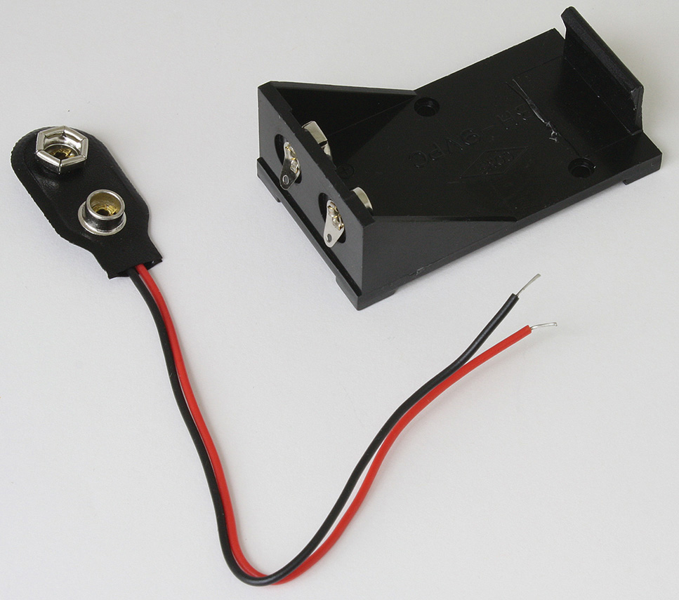
FIGURE 2-14 A 9-volt battery clip and 9-volt battery holder that is mountable.
The series connection of batteries is used often in flashlights, and even though most of them are connected in a straight line, other series connections are arranged in a zigzag manner (Figure 2-15). The two-cell flashlight uses a straight series connection of two D cells, while the LED flashlight connects three AAA batteries in series via a zigzag fashion.
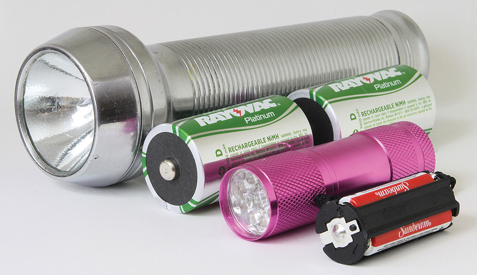
FIGURE 2-15 A two-cell regular flashlight and a three-cell LED flashlight.
NOTE Of course, there have been times when the batteries are put in series the wrong way, such as connecting the positive (+) terminal of one battery to the positive (+) terminal of another battery in a two-cell flashlight that results in no light when the switch is turned on. And if the batteries are connected with the negative (–) terminal of the first battery connected to the negative (–) terminal of the second battery, the two-cell flashlight will also fail to light up when switched on. The reason is that with two batteries of the same voltage (e.g., 1.5 volts) connected back to back with the same polarity terminals, the voltage across the two batteries is (1.5 volts – 1.5 volts) = 0 volt.
You will see later that this back-to-back series connection of two equal voltage sources yields 0 volt and is a basic principle of why capacitors block direct current (DC).
CAUTION A question does come up: Can we connect batteries in parallel? That is where the positive terminal of a first battery is connected to the second battery’s positive terminal and where the negative terminal of each battery is connected together. The answer is generally and almost always no! The reason is first of all that the batteries have to have the same voltage and must be of the same type. But even if two batteries are marked of the same voltage, one battery may be more used up than the other, and what will happen is that the stronger battery will start charging the weaker battery. This charging effect may cause large currents to flow into the weaker battery, which then may cause heating or a bad chemical reaction that can lead to leaking. Therefore, for safety reasons, parallel connections of batteries are to be avoided.
A “Second Hack”: Increasing Battery Life on an LED Keychain Light
Many LED keychain lights use two CR2016 batteries, which are rated at about 90 mAh. When the switch is turned on, the applied voltage to the white LED is supposed to be about 6 volts due to the series connection of the two CR2016 batteries. The LED actually does not receive 6 volts applied to it because the CR2016 batteries each have a built-in internal resistance, which causes a voltage drop. Nevertheless, the LED drains in excess of 50 mA, which then limits the battery life to about 2 hours given the 90-mAh capacity of the CR2016 batteries. Now suppose that we do not really need the LED to go to full brightness, and sufficient light is given at less than 10 mA into the LED.
If we replace the two CR2016 batteries with a single CR2032 in the LED keychain light, two things happen. One is the increased capacity of the 240-mAh CR2032, which is almost three times the capacity of a CR2016. The second thing is that the LED current drops dramatically to about 6 mA because there is only 3 volts from the CR2032 that is supplied to the LED.
In practice, only a few milliamps are needed to provide sufficient light for shining light in the dark when opening a lock or searching for items up close. The reason is that the white LED is very efficient.
Although most people may assume that you need at least 3 volts to turn on the LED, actually, a voltage of 2.4 volts is sufficient to light up the white LED. The CR2032 will give at least 80 percent more useful service life when it drops from 3.0 volts to about 2.4 volts. We can then estimate that the milliampere-hour rating is prorated to 80 percent of 240 or 192 mAh. The useful life of the keychain light is then about 192 mAh/6 mA, or about 32 hours. This is better than the 2 hours using the two CR2016 batteries, granted that the original light using two CR2016 batteries gives more light. See Figure 2-16.
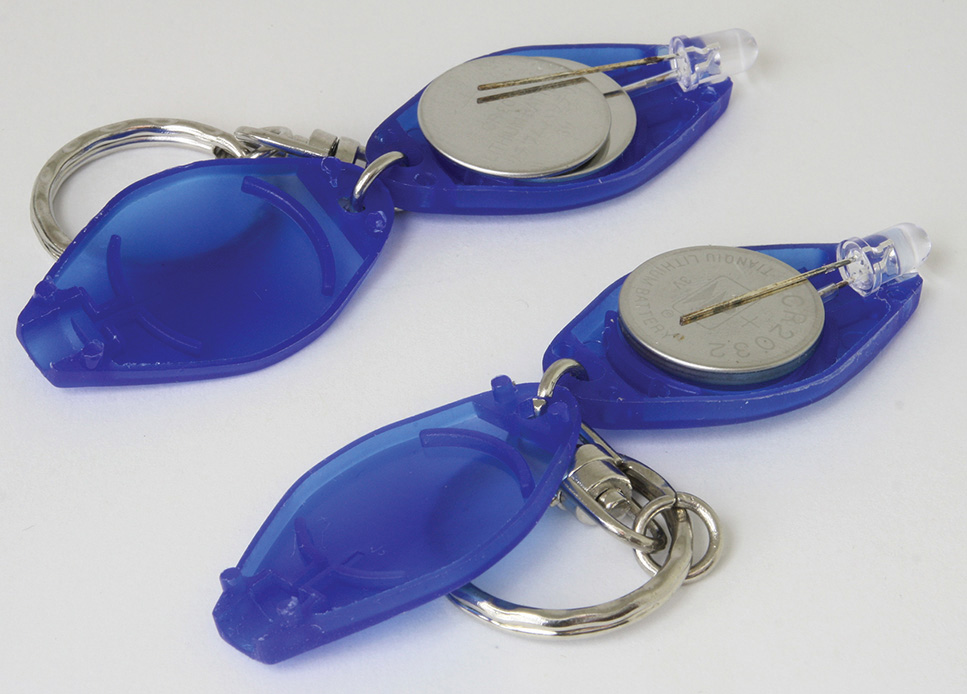
FIGURE 2-16 Two CR2016 batteries are removed and replaced with a single CR2032 battery to increase the service life of the keychain light.
From Yesteryear: A “Third Hack” by Converting a AA Cell Into a Penlight
From at least the 1950s to about 2000, the Eveready Battery Company used cardboard for the outside jacket of its carbon-zinc batteries, which were numbered 915, 1015, and 1215 for AA cells. The company also used this same material for its carbon-zinc C (#935) and D (#950) cells. Most other companies, such as Ray-O-Vac and Burgess (Gould), used a metal outer jacket instead of the cardboard tubing that Eveready used.
Today, virtually every carbon-zinc battery has a metallic outer case or is wrapped in plastic. Therefore, performing this third hack is virtually impossible today unless one can find a AA cell that has a cardboard outer casing. Note: eBay sometimes has these types of old AA batteries on auction, but their prices can be extravagant. Figure 2-17 that shows with the exception of the first battery, an alkaline power cell with a metal casing, the rest of the AA batteries have the now-obsolete cardboard outer case.
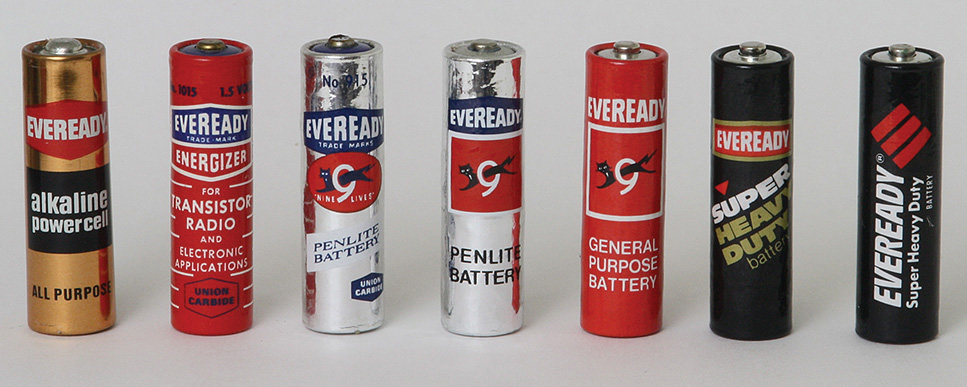
FIGURE 2-17 Various Eveready AA batteries that are now obsolete.
The first battery on the left in Figure 2-17 shows Eveready’s first marketed alkaline AA cell, which was called an alkaline power cell and not the Energizer. And dating back to the early 1960s or even prior to that, Eveready had named at least some of its batteries the Eveready Energizer. The second battery in Figure 2-17, a carbon-zinc AA cell, was used for “transistor radio and electronic applications.”
As a kid, I wanted to know what was inside a carbon-zinc battery but found that the metal jacket for the other batteries was harder to open as opposed to simply cutting off the bottom of an Eveready battery (see Figure 2-18).
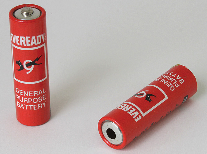
FIGURE 2-18 Left is an old AA cell. Right is the result of opening the old Eveready AA cell using a knife to remove its bottom.
After removing the bare battery, one will see that the cardboard tub includes a hole on the top to allow the positive (+) electrode of the bare battery to come through. This hole is then a convenient place to position a prefocus lamp such as the #112 bulb such that light shines out from the top of this cardboard tube.
Eat Your Spinach and Make a Flashlight!
All that is needed is a wire, which at that time I took from the paper-wire wrap for fresh spinach (see Figure 2-19). This paper-wire wrap is stripped of its paper, leaving only the conductive bare wire. However, the paper wire may have residual glue on it that acts as an insulator. The glue may be removed a number of ways from the wire, but a quick method is to simply use fine sandpaper or emery cloth (see Figure 2-20).
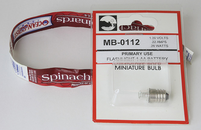
FIGURE 2-19 Paper-wire wrap and #112 bulb.
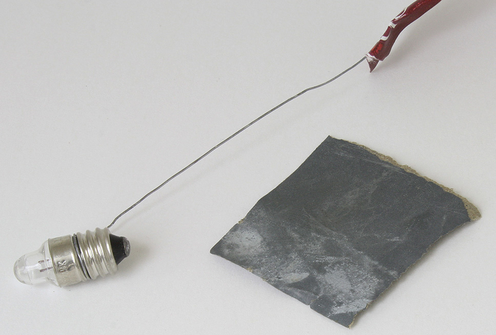
FIGURE 2-20 The wire is cleaned so as to be uninsulated via sanding off the residual glue once the paper has been removed.
In Figure 2-20, once the wire is cleaned, a small length of the wire is then wrapped around the threads of the #112 bulb with an extra length supplied to allow “threading” the wire-bulb assembly into the cardboard tube up to the top hole.
If the original obsolete battery from Figure 2-18 is still good, I would just simply reinsert that battery back into the cardboard tubing, and I would have a working penlight. However, because the bare battery from Figure 2-18 is really exhausted due to the fact that it is too many years old, I will need to find another bare AA cell that still has ample energy to light up the bulb.
It turns out that today’s metal-case carbon-zinc AA cells can be taken apart with a small pair of long-nose pliers to pry open the seam (Figures 2-21 and 2-22). Again, the pair of long-nose pliers works as a useful tool for taking apart batteries.
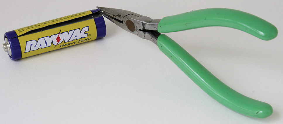
FIGURE 2-21 Prying open a present-day carbon AA cell with a pair of long-nose pliers.
FIGURE 2-22 The present-day carbon-zinc AA battery with the outer case pried open and its bare battery with plastic insulation being removed.
With the inner plastic wrapping removed, the small diameter allows the bare battery to actually fit into the cardboard tube casing shown in Figure 2-18 on the right. The flashlight now can be assembled (Figure 2-23). Finally, just insert the bare battery into the tube, and push the battery until the lamp lights up (Figure 2-24). To turn off the flashlight, simply pull the bare battery back, as shown in Figure 2-25.
FIGURE 2-23 Wire and bulb assembly and resulting insertion into the cardboard tubing.

FIGURE 2-24 The completed flashlight.
FIGURE 2-25 The flashlight is turned off by pulling out the bare battery slightly.
We will return to lighting devices such as incandescent lamps and LEDs later. For now, let’s explore other electronic components used for building circuits. But first, let’s take a look at voltage, current, and resistance.
Brief Overview of Voltage, Current, Resistance, and Power
Previously, we have shown the different types of batteries, which are voltage sources. Voltage is sometimes referred to as the electrical pressure that moves electrons.
The flow of electrons generates current. Current is defined by the number of electrons flowing per time, such as the number of coulombs per second. A coulomb is a measure of electron charge.
The following is more of a Jeopardy TV game show answer: The answer is 1.6 × 10⁻¹⁹ coulomb.
The Jeopardy question is then: What is the charge of an electron?
That is, one electron charge provides 1.6 × 10⁻¹⁹ coulomb.
How about resistance? What is resistance? Resistance is the ability to restrict or reduce the current or, put another way, to reduce the flow of electrons. For example, one way to reduce the current into your 8-ohm loudspeaker and thus reduce its sound output is to place a 16-ohm resistor in series with one of the speaker cables. It should be noted that hooking resistors in series results in the addition of the resistances.
Ohm’s law states that:
I = V/R
Again, the current I is measured in amperes (amps, A), and the voltage V is measured in volts.
The resistance R is measured in ohms—pretty good having the measurement of resistance named after the creator of Ohm’s law, George Simon Ohm.
Going back to the loudspeaker, let’s assume that V is an alternating-current (AC) voltage of 24 volts (don’t worry, we will get into AC signals and circuits later). For now, just take a look at the numbers. Without placing the 16-ohm resistor in series with the 8-ohm loudspeaker the current is
I = V/R = (24 volts)/(8 ohms) = 3 amps
Now let’s insert the 16-ohm resistor in series with the 8-ohm loudspeaker. The “new” resistance R is now 8 ohms plus 16 ohms = 24 ohms. Thus, R = 24 ohms. See Figure 2-26. Now we have
FIGURE 2-26 Amplifier with a 16-ohm resistor in series with an 8-ohm loudspeaker.
I = V/R = (24 volts)/(24 ohms) = 1 amp
Note that adding a 16-ohm resistor in series with an 8-ohm loudspeaker made the speaker’s current drop from 3 amps to 1 amp. Stated in another way, the 16 ohms of added resistance caused the current into the speaker to be reduced to one-third the original current.
To bring the speaker’s current back up to the 3-amp level requires that the voltage source V increase threefold from 24 volts AC to 72 volts AC. For V = 72 volts,
I = V/R = (72 volts)/(24 ohms) = 3 amps
Therefore, raising the electrical pressure threefold in V restored the 3 amps of speaker current. So one way to offset electric current constriction/reduction due to resistance is to increase the source voltage.
Now we will look at Ohm’s law as applied to power. There are other types of voltage sources such as AC adapters that provide a voltage and a rated current. For example, a typical laptop AC adapter receives 110 volts AC from the wall outlet and provides about 20 volts DC with a current capability of 3 amps. In terms of power capability, this AC adapter provides a maximum 60 watts of power. So how did I get this number?
Ohm’s law states that power is equal to voltage times current. Or, alternatively stated:
P = V × I
This also can be written as
P = VI
where P is power in watts
V is voltage in volts
I is current in amps (A)
Thus, 60 watts is equal to (20 volts × 3 amps).
What if we have a smaller AC adapter used for lower-powered circuits? For example, what would be the power capability of an AC adapter that gives out 15 volts DC but only a maximum of 150 mA?
First, we convert the 150 mA to some number of amps. To convert milliamps to amps, divide by 1,000. Therefore,
150 mA = (150/1,000) amps = 0.150 amp
The maximum power from this smaller AC adapter is then
(15 volts × 0.150 amp) = 2.25 watts
Power produces heat such as in an electric blanket, light as in an LED, sound as in a loudspeaker, or motion as in a motor.
Resistors
Resistors are devices that limit current in a circuit, and they also can be used in voltage divider, filter, and amplifying circuits. They are available from ⅛ watt to at least 2 watts in terms of power dissipation. Resistor values have a specific tolerance from 0.1 percent to 10 percent. For this book, the most common resistors that we will use are ¼-watt 5 percent and 1 percent types. For resistors up to 2 watts, usually there are four bands painted on the resistor to denote its value. See Figure 2-27 and Tables 2-3 and 2-4. Note that resistor values are measured in ohms.
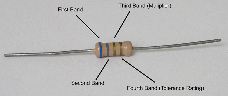
FIGURE 2-27 A resistor with four bands.
TABLE 2-3 Resistance Values for the First Three Bands

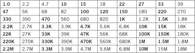
TABLE 2-4 Typical Values for Resistors
It should be noted that the gold and silver bands are usually in the third bands when denoting a value for a resistor. In the fourth band position, gold = 5 percent and silver = 10 percent. The first two bands denote a number, while the third band denotes how many zeroes are added to the first two numbers. For example, a 10,000-ohm 5 percent resistor is denoted as brown, black, orange, and gold, which is interpreted as “10 plus three zeros following = 10 000 or 10,000.” With 5 percent tolerance, this means that the value of the resistor is 10,000 ohms plus or minus 5 percent of 10,000 ohms or 10,000 ohms ± 500 ohms. Therefore, this example resistor can fall within the range of 9,500 ohms to 10,500 ohms.
To shorten the number of zeroes when writing a resistor value, we assign k = 1,000 and M (or mega or Meg) = 1,000,000. For example, a 10,000 ohm resistor is the same as a 10k ohm resistor, or a 10,000,000 ohm resistor is the same as a 10 M ohm or 10 Meg ohm resistor.
Some typical values of resistor are shown in Table 2-4. More commonly used values are shown in bold fonts.
There are “in-between” values (in ohms) that are not shown for 5 percent resistors, such as 12, 13, 16, 20, 24, 30, 36, 43, 51, 75, and 91. These in-between values may be multiplied by 0.1, 10, 100, 1,000, and 10,000 to provide other resistance values. For example, multiplying by 0.1 yields values of 1.2, 1.3, and so on. If we multiply by 100, we get in-between values of 1,200, 1,300, …, 9,100.
For 1 percent resistors, there are five bands, and the first three bands represent three digits, followed by the fourth band, which is the added number of zeroes following the three digits. The fifth band is always brown for denoting a 1 percent tolerance (see Figure 2-28).
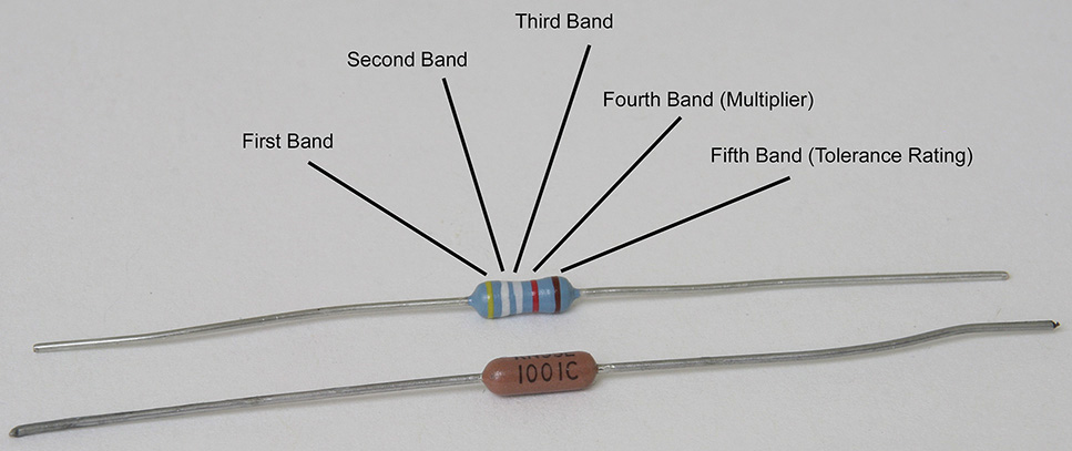
FIGURE 2-28 A 1 percent tolerance resistor with five bands.
For the resistor at the top of Figure 2-28, the first three bands denote the first three digits, while the fourth band is the multiplier. We read the resistor using the first four bands, but from which side of the resistor? The four bands that tell us the value of the resistor always have equal spacing separating these four bands. If one looks very closely, one will notice that the spacing between the fourth and fifth band in Figure 2-28 is wider than the spacing between the first and second, second and third, or third and fourth bands.
The bottom resistor in Figure 2-28 has its value printed on it instead of using a color code. Here the first three numbers represent the first three digits, followed by the fourth number, which is the multiplier (or number of zeroes added to the three digits). In this example, the resistor reads “1001C,” which is 100 + “1 zero” = 1,000 ohms. The C denotes the tolerance, which is coded as 0.25 percent. For precision resistors, A = 0.05%, B = 0.10%, C = 0.25%, D = 0.50%, F = 1.0%, and G = 2%. Sorry, but there is no designation for E.
It’s All Greek to Me, But It’s Good
Instead of writing the word ohms, a shorthand notation is used employing last letter of the Greek alphabet, omega. The upper case or capital letter omega is Ω, which denotes ohms. We can substitute Ω wherever ohm or ohms is used to describe the values of resistors. For example, 1,000 ohms is expressed as 1,000 Ω.
For resistors greater than 2 watts, we have power resistors. Fortunately, they have their resistance values, power rating, and tolerance printed on them. (Note that the color code is not normally used in power resistors of 3 watts or more.) See Figure 2-29.
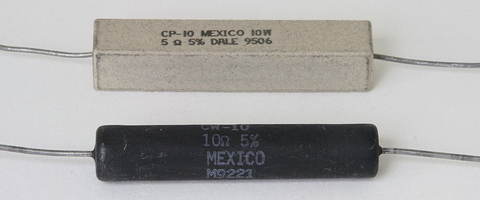
FIGURE 2-29 These resistors are wire-wound types at 5 Ω 5% 10 watts and 10 Ω 5% 10 watts.
So how do we find out the power going into a device such as a resistor? From Ohm’s law,
P = VI
To determine the power absorbed or dissipated in a resistor we need to express P in terms of resistance. We also know that:
I = V/R = (V/R)
Let’s substitute this equation into the power equation so that:
P = VI = P = V(V/R) = (VV/R)= (V)2/R
P = (V)2/R
NOTE P is measured in watts when the voltage V is measured in volts and the resistance R is measured in ohms. Note that “w” denotes watt.
The equation, P = (V)2/R, is probably the most common method of assessing the power absorbed into a resistor. It’s also easy to just measure the voltage across the resistor. Just square the voltage and divide by the resistance to get the power dissipated by the resistor. For example, suppose that there are 25 volts across a 1K ohm (1-kΩ) resistor. The power is then:
P = (25 volts)2/1 kΩ = (625/1,000) watt = 0.625 watt = 0.625 w = P
A rule of thumb is to specify a resistor’s wattage to be at least twice the actual power dissipation. So if there is 0.625 watt across the 1K ohm resistor, pick a 2-watt resistor for reliability. However, a 1-watt resistor would work too. If the power rating of the resistor is near the power dissipation, then chances are that the resistor will change value (e.g., increase in resistance) over time due to prolonged “excessive” heat.
There is another derivation for expressing the power dissipation of a resistor in terms of current flowing into the resistor. Again, let’s take a look at the basic equation:
P = VI
However, we also know that:
I = V/R
which says that the current through the resistor is the voltage divided by its resistance value. Put in another way, if a current I is flowing into a resistor R, a voltage will be developed across the resistor. This means that:
V = I ×R = IR
Thus,
V = IR
The voltage V is the voltage across the resistor when current is flowing into it.
Now let’s review what we have:
P = VI
V = IR
By substitution of V, we get
P = VI = (V) I = (IR)I = IRI = IIR = (I)2R=P
This leads to:
P = (I)2R
NOTE P is measured in watts when the current I is measured in amps and the resistance R is measured in ohms.
For example, if we know that there are 1.5 amps DC flowing into a 22-Ω resistor, then the power dissipated into the resistor is
P = (I)2R = (1.5)222 watts = 2.25 × 22 watts = 49.5 watts
In this example, for reliable operation, a 100-watt power resistor should be chosen.
A next logical component to cover is the capacitor. Capacitors are storage devices. When voltage is applied to a capacitor, a charge is stored inside the capacitor. The ability of the capacitor to hold a charge makes the capacitor sort of like a low-capacity rechargeable battery.
Capacitors
Whereas resistors are measured in ohms, capacitors are measured by their capacitance in farads. However, a farad is a very large amount of capacitance, so most capacitors have values of microfarads or picofarads of capacitance. A microfarad (μF) is one-millionth of a farad. And a picofarad (pF) is one-millionth of a millionth of a farad or a millionth of a microfarad. Another commonly used term to denote capacitance is the nanofarad (nF), which is one-billionth of a farad. And just in case you are wondering, the farad is named after Michael Faraday.
Capacitors are made of two plates separated by an insulator, otherwise known as a dielectric. A general formula for capacitance is
C = kAε0/d
The constant k is the dielectric constant. For example, the dielectric constant of a vacuum or air is about 1, whereas the dielectric constant of ceramic material is about 3 to 7. A is the area of the plates, ε0 is the emissivity constant (don’t worry about this because we will not be making any calculations), and d is the distance between the two plates.
From this formula, intuitively, it makes sense that the closer the plates are, the smaller is the number for d, which results in more capacitance. In addition, if the area of the plates increases, then A increases, which also increases the capacitance. Also, depending on the dielectric material that governs k, the capacitance can be increased or decreased.
One advantage of a capacitor is that it can be quickly charged by putting a voltage source across the terminals. The discharge rate is related to how much capacitance there is in the capacitor.
For a quick understanding of how capacitors work, for a DC voltage, think of a capacitor as a low-capacity rechargeable battery. A capacitor can hold a charge like a battery but cannot power a device for long periods like a battery. For AC voltage, a capacitor acts sort of like a resistor, except that it does not get hot. It resists or controls AC current but does not dissipate heat because during one part of the AC signal it is charging up like a battery and during the other part of the AC signal it is discharging current, and the net charge and discharge current sum to zero. This is why a perfect capacitor never gets hot!
Because of the storage capability of capacitors, they are used in power supplies. When you shut off your laptop computer and then pull the plug from the AC outlet, you will notice in some laptop AC adapters the indicator light is still on for a few seconds before it goes out. The capacitor in the AC adapter has stored enough electricity to light up the LED lamp after the AC power has been removed. Capacitors used in power supplies provide filtering at low frequencies to remove hum are called electrolytic capacitors.
NOTE Electrolytic capacitors in general are polarized. That is, there is usually a (–) marking or a (+) marking on the capacitor. The polarity of the capacitor must be observed and connected correctly. For example, to charge up an electrolytic capacitor with a battery, connect the (–) terminal of the battery to the (–) terminal of the capacitor and likewise with the (+) terminal.
WARNING Improperly connecting an electrolytic capacitor may lead to an unsafe situation.
Electrolytic capacitors have markings for correctly applying DC voltage to them. For electrolytic capacitors that have axial leads, usually the outer can or case is the (–) polarity of the capacitor. In radial-lead electrolytic capacitors, the (–) terminal is clearly marked on one side. Figure 2-30 shows axial- and radial-lead electrolytic capacitors. Note that electrolytic capacitors have voltage ratings that always should exceed the voltage applied to them. In general, the voltage rating should exceed the supply voltage, for instance, by at least 30 percent. For example, if the circuit operates at 12 volts DC, all electrolytic capacitors should have a voltage rating of at least 16 volts. Also, electrolytic capacitors have a tolerance of at least 20 percent. Some are specified at –20 percent and +80 percent, and these are generally used in power supplies.
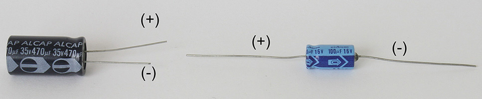
FIGURE 2-30 Axial- and radial-lead capacitors with polarity markings.
In some circuits involving AC (alternating current) signals where the average DC (direct current) voltage is about 0 volt, a nonpolarized electrolytic capacitor can be used. Alternatively, two equal “regular” electrolytic capacitors may be soldered back to back in series with either the (–) and (–) or (+) and (+) terminals. The resulting capacitance is half. For example, soldering two 100-μF electrolytic capacitors soldered back to back in series results in a 50-μF nonpolarized capacitor. See Figure 2-31 for an illustration of back-to-back connections.
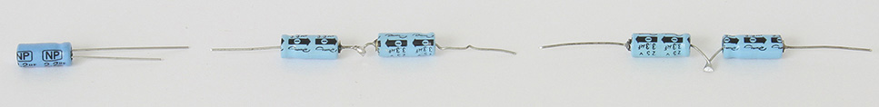
FIGURE 2-31 (From left to right) A nonpolarized electrolytic capacitor and two electrolytic capacitors connected with their (–) terminals and two electrolytic capacitors connected back to back with their (+) terminals.
Smaller-value capacitors of 2.2 μF and under are generally nonpolarized, which means that you can connect these capacitors without regard to polarity. Capacitors are generally marked with a three-digit number, where the first two numbers are significant and the third number denotes the number of zeroes added to the first two numbers in units of picofarads. The tolerance is denoted by a letter such as K = 10%, J = 5%, G = 2%, and F = 1%. For example, a 0.01-μF 10 percent tolerance capacitor is marked 103K or 10,000 pF = 0.01 μF. When in doubt about the value, you can measure the capacitance with a capacitance meter, which is usually available in a digital voltmeter costing $20 or more. The voltage rating is usually at least 25 or 50 volts, and the exact voltage rating is rarely marked on the capacitor itself, but it is known when it is ordered from a vendor (e.g., www.mouser.com or www.digikey.com). Figure 2-32 shows various types of small-valued capacitors that include ceramic disc, ceramic monolithic, film, and silver-mica capacitors.
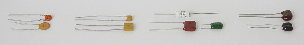
FIGURE 2-32 Ceramic disc, ceramic monolithic, film (e.g., mylar or polyester), and silver-mica capacitors.
Inductors or Coils
An inductor is yet another storage element that works on the principle of magnetic flux or magnetic fields. Its property is that ideally it has zero DC resistance but has an AC resistance just like a capacitor.
Whereas a capacitor’s AC resistance decreases with increases in frequency, an inductor has an opposite characteristic. Instead, as the AC frequency increases, the AC resistance of an inductor increases.
In radio-frequency (RF) circuits, inductors are used in oscillators and band-pass filters. For example, inductors are used in inductor-capacitor oscillators such as a Colpitts oscillator. And inductors can serve as both an inductor and an antenna coil such as those used in an AM radio.
Inductors are used in power-supply circuits to filter out hum or high-frequency noise. They are used in switching power supplies to boost the voltage. For example, an inductor with a switching power-supply circuit can convert the 1.5 volts from a battery to a 4 volt output to light up white light emitting diodes (LEDs) (Figure 2-33).
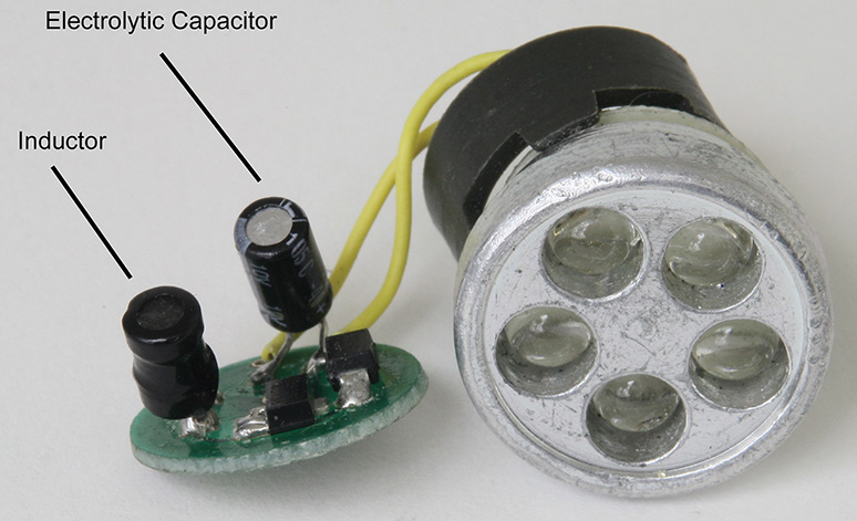
FIGURE 2-33 A miniature switching power supply inside an LED flashlight with an inductor.
Figure 2-33 shows the internal circuitry of a AAA-cell LED flashlight. Because the white LEDs need at least 2.5 volts for lighting, the 1.5 volts from the AAA cell is not sufficient. The inductor in conjunction with the switching power-supply chip, rectifier, and aluminum electrolytic capacitor converts the 1.5 volts from the battery to about 4 volts, which is then sufficient to light up the white LEDs.
While it is normally difficult to make your own resistor or capacitor, it’s easy to make an inductor. As a matter of fact, even a straight piece of wire can be used as an inductor for very high-frequency circuits. A practical way to make an inductor is to wrap wire around an empty roll of bathroom tissue, a plastic pen, or a ferrite bar. See Figure 2-34.
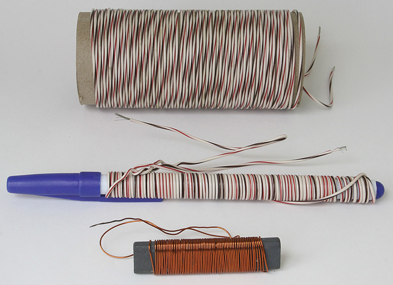
FIGURE 2-34 Do-it-yourself (DIY) inductors.
Resistors are measured in ohms, capacitors are measured in farads, and inductors are measured in henries (H), named after Joseph Henry. A measure of inductance is therefore the henry. Inductors that require values in the order of henries are limited to low-frequency applications such as a 60-hertz (Hz) power supply for tube amplifiers or for an audio effects circuit such as a “wah-wah” sound-effects circuit for modifying the tone of a musical instrument. Most coils have much lower inductances, especially those used in RF and audio circuits. For RF circuits, the inductances are in the nanohenry to microhenry range (one-billionth of a henry to one-millionth of a henry), and for audio circuits, typical inductances are in the millihenries range (one-thousandth of a henry).
For the coils shown in Figure 2-34, the bathroom tissue inductor has about 75 microhenries (75 μH), while the pen coil measures at 5.6 μH, and finally, the ferrite bar (antenna) coil measures the most at 180 μH. The ferrite material magnifies the inductance, so a smaller number of turns is required to provide the same amount of inductance as would be required for an air-core inductor. To reiterate, most inductors have inductances in microhenries (μH) that are used in RF (radio-frequency) circuits, while some audio circuits may use millihenry (mH) coils.
Some common inductors look like resistors and even have the same color code as resistors. However, they are distinguished in that when they are measured for resistance, the resistance value is often much lower than what the color-code marking would imply. See Figure 2-35.
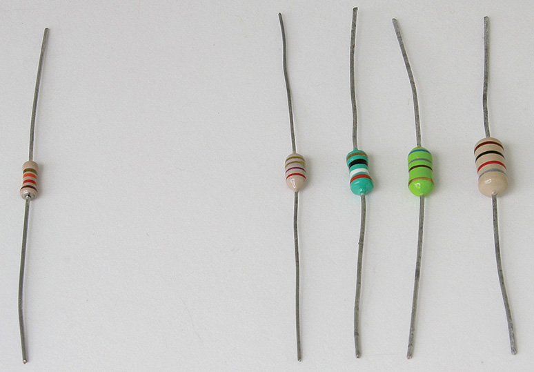
FIGURE 2-35 A resistor on the left and four inductors on the right.
The color code that is used for inductors is the same as that for resistors, and the inductance values are from the 10 percent resistor values. The first two color bands denote the first two digits, and the third band is the multiplier or number of zeroes following the two digits to determine the inductance in microhenries. The fourth band is the tolerance, usually silver for 10 percent or gold for 5 percent tolerance. For example, an inductor with yellow-violet-orange-silver bands is rated at 47,000 μH at 10 percent tolerance. To convert microhenries to millihenries, divide the microhenry number by 1,000 to arrive at the millihenry value.
From this example inductor,
47,000 μH = [47,000/1,000]mH = 47 mH = 47,000 μH
One way to identify an inductor or a resistor is to read the color code and then measure it with an ohmmeter. In the example shown in Figure 2-36, a “component” with color-coded bands of orange, white, black, and gold would normally read as a 39-ohm 5 percent resistor. But see what happens when we test it with an ohmmeter. See Figure 2-36.
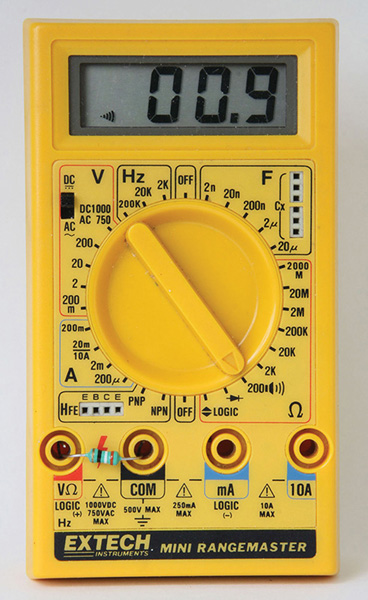
FIGURE 2-36 A 39-μH inductor tested for resistance.
The 39-μH inductor measures 0.9 ohm, which means the component is not a 39-ohm resistor. By deduction, the component must be an inductor. An inductor’s resistance generally does not match the value as read out by its color code. By measuring the DC resistance one can then deduce whether the component is a resistor or an inductor.
Other types of inductor have markings that show a three-digit number, with the first two digits indicating microhenries and a third digit for the multiplier or number of zeroes after the two digits for the inductance value in microhenries. For example, an inductor with a marking of “470” is 47 μH (Figure 2-37).
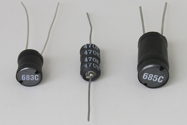
FIGURE 2-37 Inductors with three-digit markings.
Figure 2-37 shows an inductor with a marking of “683,” which normally would mean 68,000 μH = 6.8 mH. Actually, in this case and in the last inductor with a marking of “685,” that could mean 6,800,000 μH = 6.8 henries, the units of inductance are in nanohenries instead of microhenries. A nanohenry is 1 billionth of a henry and is a thousand times smaller than a microhenry. So this makes the first inductor in the figure actually a thousand-fold less than expected and thus 683 → 68 μH and 685 → 6.8 mH.
The only inductor that measures as expected is the middle coil that reads “470,” which is 47 μH. Recall that the third number is the number of zeroes following the first two digits, that is,
470 → (47 + no zero added)μH = 47 μH
The best way to verify if an inductor really is an inductor is to measure it with an inexpensive inductance meter such as the one shown in Figure 2-38, which costs about $40 on eBay. From Figure 2-38, the first inductor from Figure 2-37 with the marking “683C” measures about 64 μH, which then identifies that inductor as a 68-μH inductor. We will now venture into the world of semiconductors but will include vacuum tubes as well.
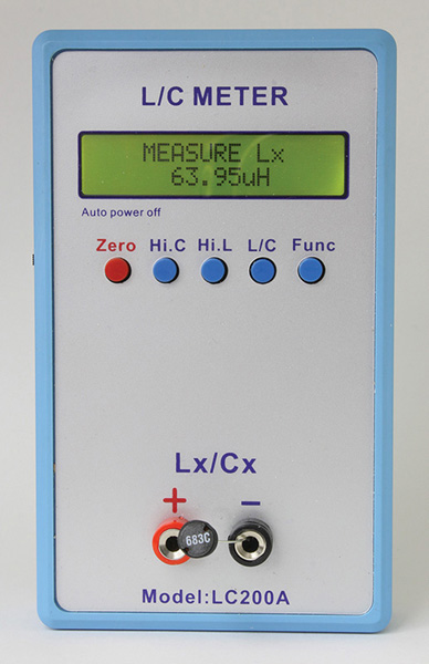
FIGURE 2-38 An inexpensive inductance-capacitance L/C meter capable of measuring both inductance and capacitance.
Semiconductors
There will be more detail about semiconductors in Chapters 4, 5, and 7. For now we will present a brief overview.
Diodes and Rectifiers
Diodes and rectifiers allow electricity to flow in one direction (e.g., with low resistance) while providing an open circuit (e.g., very high resistance) in the other direction. They are thus useful in converting an AC (alternating current) signal that, by definition, has part of the time a positive voltage and at another time a negative voltage to provide a voltage that is either positive or negative. For example, an AC adapter uses one or more rectifiers to provide either a positive or negative DC voltage. For small signals such as converting an AC AM signal to a DC signal, diodes are used. See the first two diodes (top and middle) in Figure 2-39.
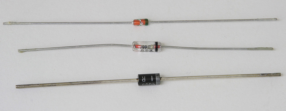
FIGURE 2-39 Diodes and a rectifier with bands to denote their cathodes.
For small-signal diodes, there are mostly standard silicon diodes such as the 1N914 or 1N4148. These diodes are generally used for switching, RF, and biasing circuits. In contrast, silicon rectifier diodes are generally not suitable for RF (radio-frequency) circuits but are suitable for higher-power applications such as power rectifiers for 50 Hz or 60 Hz AC power supplies.
The turn-on voltage of the standard silicon diode or rectifier is about 0.6 volt. For lower turn-on voltages, the Shottky diodes and Shottky rectifiers have turn-on voltages of 0.3 volt to 0.4 volt. In power supplies where the minimum losses are required, the Shottky diode is a prime source. For example, the rectifier used in the LED flashlight shown in Figure 2-33 is a power Shottky diode.
For older germanium diodes, the turn-on voltage is in the range of 0.1 volt to 0.25 volt. Common part numbers for germanium diodes are 1N34, 1N60, and 1N270. These diodes are generally used in radio circuits.
But what’s a diode turn-on voltage? An idea diode when the polarity is set for forward conduction is supposed to have 0 volt. That is, for any voltage ≥ 0 volt (greater than or equal to zero volt), the ideal diode will pass the voltage through. And at any voltage < 0 volt (less than zero volt), the ideal diode will stop current flow and not pass any negative voltage through the diode. In any diode, there is a minimum threshold voltage before conduction starts. This threshold voltage is the turn-on voltage. There will be some experiments later on for the reader to get acquainted with diodes. For now, the diode or rectifier has two terminals—the anode and the cathode. The cathode is marked with a band. See Figure 2-39.
Figure 2-39 shows on the top, a common silicon small-signal diode such as the 1N914 or 1N4148 diode. The middle section shows a larger glass diode such as a germanium 1N34 or 1N270 diode. On the bottom, we see a power rectifier such as a 1N4003 power supply rectifier.
Generally, diodes are used for smaller signals such as AM detectors or voltage references. Rectifiers are actually diodes, but we refer to them as rectifiers for higher-power situations such as use in power supplies.
For those diodes that are made of glass, an extra lead length is required to prevent cracking of the glass body when loaded on a board. Bending the leads too close to the body causes damage at the edges of the glass diode. See Figure 2-40. Because rectifiers handle power, the leads of a rectifier act as a heat sink to allow cooling of the rectifier. Therefore, the leads are also not bent too close to the body.
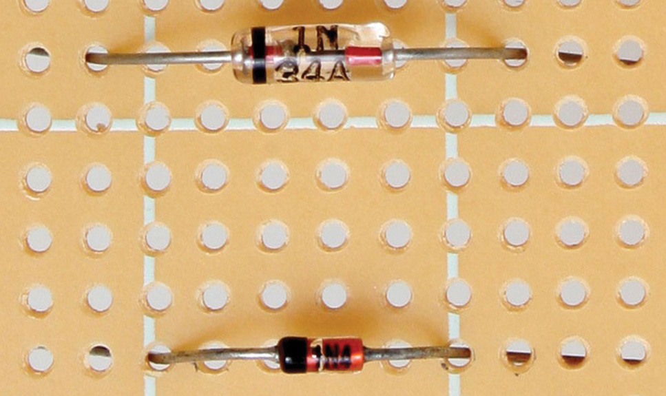
FIGURE 2-40 Examples of spreading out the leads when mounting diodes on a board to avoid cracking the glass body.
Rectifiers are rated by their peak reverse voltage (PRV), but the older equivalent term is peak inverse voltage (PIV). Also they are rated for their forward-bias conduction current. Typical power diodes or rectifiers are rated at 1 amp, 3 amps, etc. For example, a 1N4001 rectifier has a PRV of 50 volts. This means that it will still conduct when the voltage applied to the anode is greater than + 0.6 volts, and will not conduct if the voltage is between –50 volts and 0 volt. If the negative voltage is more negative than –50 volts, such as –60 volts, the diode will start conducting again.
Common 1-amp rectifiers are
• 1N4001 50 PIV
• 1N4002 100 PIV
• 1N4003 200 PIV
• 1N4004 400 PIV
• 1N4005 600 PIV
• 1N4006 800 PIV
• 1N4007 1000 PIV
Amplifying Devices
An amplifier sometimes is defined as a device or system that makes a small or weak signal larger or stronger. This statement alone needs a qualifier in that the amplifying device or system requires power to make the signal larger. An amplifier is powered via an external DC source such as a DC power supply or a set of batteries. The external power source allows the amplifier to use a small signal at the input such as a signal from a microphone to control larger signals at the output of the amplifier. For example, a typical microphone does not have sufficient power output to drive a loudspeaker directly. If the microphone is connected to an amplifier that is connected to a loudspeaker, we can then drive the loudspeaker and make a whisper very loud. In FM radios, for example, at the antenna, the off-the-air signals may be as low as 10 millionths of a volt (10 μV). But by connecting one amplifier after another in the radio, the signal may be brought up to a level of 1 volt, which in this case results in a voltage gain of 100,000.
A relay consists of a coil that forms an electromagnet in conjunction with an actuator switch. The actuator switch controls its switch contacts to open or close, that is, to stop or allow current to flow. If there is enough current flowing through the coil, the relay switch contacts can control power by turning on very large amounts of current to a device such as a 100-watt lamp. Typically, the coil only needs a small amount of power such as 1 watt to activate the relay. In this case we have a 100:1 power gain because we have 100 watts of output for a 1-watt input signal. Thus the relay can be thought of as an amplifying device. However, on the surface, the relay only turns on or off—it’s a digital signal. That is, the relay coil either pulls the contacts together to switch on or it does not.
For amplifiers, what we are commonly talking about are the ones that amplify an analog signal such as music or speech signals. Since music or speech signals are not merely on and off signals, the relay cannot normally be used as an amplifier the same way a common stereo hifi amplifier works.
Bipolar Transistors
For small-signal amplification such as radio receiver circuits, preamplifiers, video amplifiers, and so on, the plastic-case TO-92 transistor is commonly used. Small metal-case transistors (e.g., TO-18) are also available, such as the 2N2222 and 2N2907, which offer a bit more current and power capability than some TO-92 versions.
Power transistors are utilized to deliver power to a load, such as providing many watts of power to a loudspeaker. For example, a typical stereo receiver has output power transistors. For medium-power applications, some TO-5 metal-case transistors are used. For this book, we will avoid TO-5 transistors since it is easier to use the plastic-case power transistors. Also, TO-5 transistors, which were popular from the 1960s to the 1980s, have fallen out of use in favor of plastic-case power transistors.
Finally, for high-power circuits, there are TO-220 and TO-218 transistors. For even higher power, the larger plastic-case TO-247 transistor is used.
Not as common today is the TO-3 metal case power transistor. We will avoid using TO-3 transistors because the installation on heat sinks is more difficult than mounting plastic-case power transistors. Also, this metal-case power transistor is not as popular as it used to be.
A bipolar transistor has three terminals—the emitter, base, and collector. And there are two types of polarities for bipolar transistors—NPN and PNP.
Amplification occurs when a small signal is connected to the base and emitter terminals that act as the input, and the output is taken off from the collector. This type of amplifier is known as a common-emitter amplifier. Another form of amplification is buffering, where the voltage gain is 1 or less, but the output is capable of driving very high currents. In this case, the input signal is connected to the base of the transistor, and the output at the emitter of the transistor supplies amplified current. For example, certain sound cards in a computer may only have enough current to drive a set of headphones at low volume. If the output of the sound card is connected to the base of a transistor and the emitter of the transistor is connected to the same set of headphones, a louder volume will result. This type of amplifier is called an emitter-follower amplifier.
Of course, there are other types of amplifiers, and they will be covered in Chapter 6 and subsequent chapters. For now, we will look at different types of small-signal and power transistors (Figure 2-41).
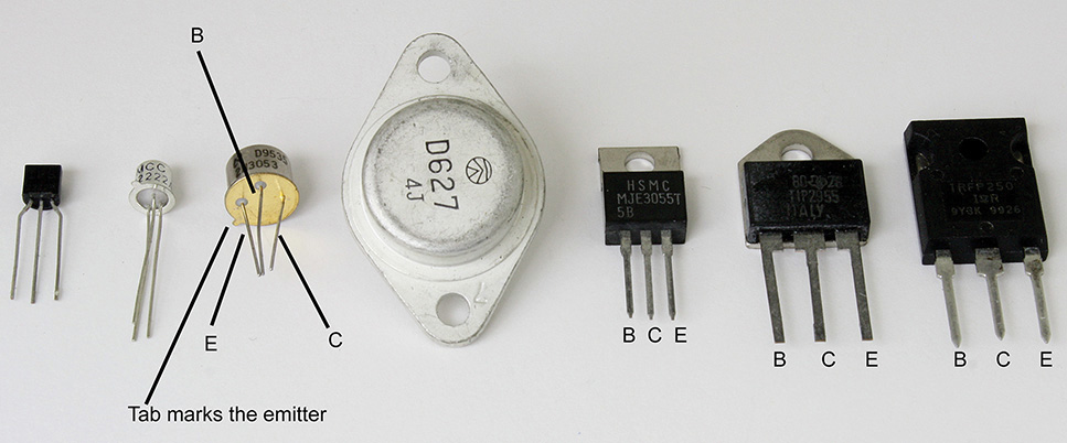
FIGURE 2-41 Various plastic- and metal-case transistors, including plastic power transistors.
In Figure 2-41, from left to right, are plastic-case TO-92, metal-case TO-18, metal-case TO-5, metal-case TO-3, plastic-case power TO-220, plastic-case power TO-218, and plastic-case power TO-247 transistors. For the TO-92 transistors, there are variations on the pin-out of the emitter base and collector (Figure 2-42).
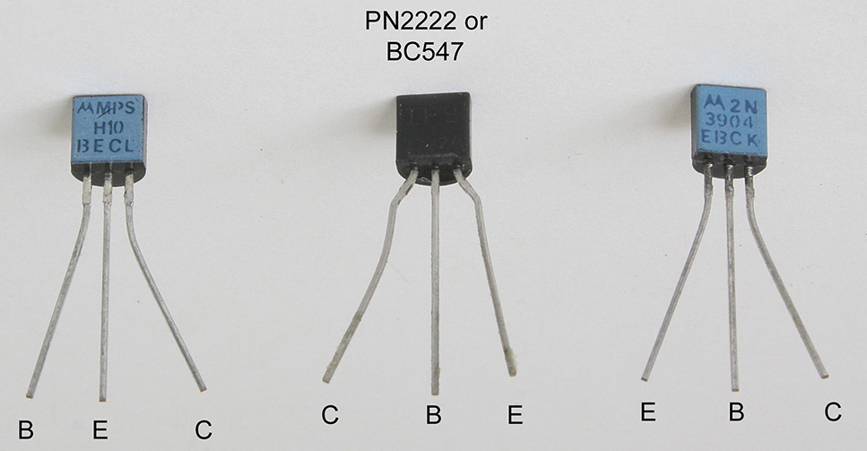
FIGURE 2-42 Emitter, base, and collector pin-outs for the MPSH10, PN2222 or BC547, and 2N3904 transistors.
The general pin-out sequence of a transistor is emitter-base-collector or collector-base-emitter. However, for very high-frequency transistors, generally it is desirable to minimize proximity between the base and the collector leads. This is why the MPSH10 high-frequency NPN transistor has a pin-out of base-emitter-collector. The emitter, which is often AC signal grounded, acts as a ground shield between the collector and base. Collector-to-base capacitance, as we will find out later, generally reduces the high-frequency response. The complementary PNP high-frequency transistor to the MPSH10 is the MPSH81, which also has the same pin-out as the MPSH10. For a list of some small-signal transistors with emitter-base-collector pin-outs, see Table 2-6. Small-signal transistors with collector-base-emitter pin-outs are listed in Table 2-7. For plastic-case power transistors, see Table 2-8. The pin-out is base-collector-emitter, with the metal tab connected to the collector terminal. See Figure 2-41 that shows B C E.
TABLE 2-6 Various NPN and PNP Small-Signal Transistors
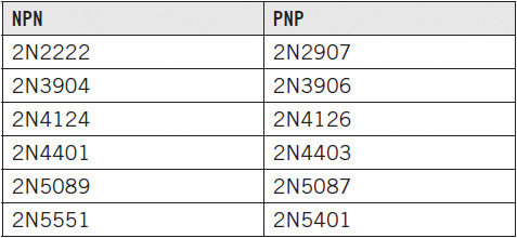
TABLE 2-7 Small-Signal Transistors with Collector-Base-Emitter Pin-Outs
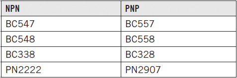
TABLE 2-8 Plastic-Case Power Transistors
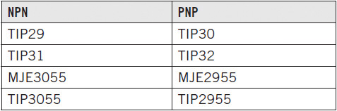
The four transistors listed as TIP29 to TIP32 are medium-power transistors capable of about 3 amps of collector current. However, the “2955” and “3055” transistors can deliver up to 15 amps.
Vacuum Tubes
One of the first vacuum tubes was merely a light bulb with an additional metal plate inside the glass bulb. This two-element device (filament and plate) was invented by Thomas Edison and is also known as a vacuum-tube diode.
To operate this device, first apply a filament power supply to light up the bulb. The Edison effect, as it became known, occurred when the inventor noticed that if a DC voltage source (negative polarity) was connected to one of the filament’s terminals (either would do) and the other terminal of the DC voltage source (positive polarity) was connected to the plate, current would flow via the plate. However, if the DC voltage source had its terminals reversed, no current would flow via the plate. You may say this was the first semiconductor, even though it was done with a hollow-state device.
Around 1907, Lee De Forest decided to build on Edison’s idea and put a see-through metal fence or grid between the filament and the plate, making this a three-element device (filament, grid, and plate) known as the triode (e.g., “modern” tubes of the 1940s and 1950s, the 6J5 and 6C4). By adding the grid, De Forest was able to control the flow of electrons to the plate of the tube by using the principle of repulsion.
We know from static electricity that like charges repel and unlike charges attract. Since electrons are negatively charged, varying a negative voltage at the grid and one terminal of the filament then controlled the current flow to the plate. The more negative the voltage is at the grid, the fewer electrons reach the plate because the grid becomes a repeller of electrons and bounces the electrons back to the filament. If the grid voltage is less negative, then fewer electrons are repelled, and more electrons get to reach the plate, thereby increasing plate current.
In the intervening years, approximately 10 years apart, second and third grids were eventually placed inside the bulb. The second added grid, a screen grid, lead to the creation of the tetrode in 1919, a four-element tube with a filament, control grid, screen grid, and plate. The pentode was invented in 1926 and was a five-element tube with a filament, control grid, screen grid, suppressor grid as the third grid, and plate. The major advantage of the tetrode and pentode over the triode is higher gain or higher amplification. Examples of tetrodes are the 12DS7 and 6CL8. As for pentodes, they are still made today for guitar and high-fidelity amplifiers such as the power-output tubes 6L6, 6550, and EL34. Smaller-signal example pentodes are the 12BA6, 12SK7, and 6CB6.
Eventually, engineers got creative and placed more grids, leading to the seven-element heptode, a five-grid tube commonly called the pentagrid converter (e.g., 12BE6, 12SA7, and 1R5), and the eight-element octode, a six-grid tube that can be called a hexagrid converter (e.g., 6A8). These tubes were used almost exclusively in radios and in audio-processing amplifiers such as an audio amplitude compressor or automatic gain control amplifier.
Because there are so many types of diodes, triodes, pentodes, heptodes, and so on that are housed in seven-, eight-, and nine-pin tubes, there is no set rule as to which pin is always assigned as the plate or grid. Also, many vacuum tubes have multiple sections, such as the twin triode (e.g., 12AT7, 12AU7, 12AX7, and 12BH7) or triode and pentode combination tubes (e.g., 6AW8, 6GH8, 6U8, and 7199).
There are many different types of tubes in terms of pin numbers. For this book, we will concentrate on the seven- and nine-pin miniature and the eight-pin octal tubes such as those shown in Figure 2-43. And the pin-number assignments as viewed from the top are shown in Figure 2-44.
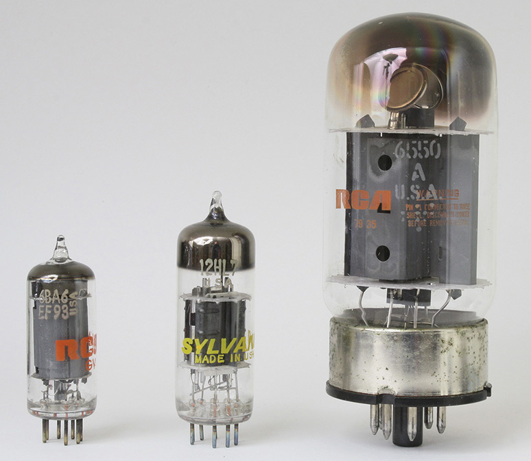
FIGURE 2-43 Vacuum-tube examples with seven, nine, and eight pins.

FIGURE 2-44 Pin assignments for the seven- and nine-pin miniature tubes and the eight-pin octal tube are shown via tube sockets.
With vacuum tubes, the pin-out convention is as follows:
1. For seven- and nine-pin tubes, from the top view as in Figure 2-44, start from the lower-right side as pin 1 and go counterclockwise for each succeeding pin number. By the time you reach the last pin on the lower-left side, that pin will be pin 7 for a seven-pin tube and pin 9 for nine-pin tube.
2. For an octal tube, again from the top view, start at the lower-right pin for pin 1, as shown in Figure 2-44 at the pin just right of the “key” or “index” marking. Again, count each number as you go counterclockwise. You should end with pin number 8 for the pin that is to the left of the “key” or “index” marking.
Integrated Circuits as Amplifiers and Logic Gates
Integrated circuits contain a number of transistors and often also contain resistors and capacitors. They provide a system function such as an amplifier, voltage regulator, radio receiver circuit, digital logic circuit, and all the way to a complicated mixed digital and analog system on a chip (SoC) or to a central processing unit (CPU) that is the heart of a laptop or desktop computer. What used to be built on hand-wired chassis or printed circuit boards are now condensed into chips or integrated circuits.
For example, look at the USB ATSC television tuners that are available today. Just plug the chip tuner into the USB port of your computer and view your favorite shows. A television tuner built in the early 1980s would have required printed circuit boards, transistors, RF coils, high-frequency transformers, capacitors, mechanical switches, etc. It would have been relatively large—about the size of a 23-watt compact fluorescent bulb. For this chapter, we will just concentrate on 8-, 14-, and 16-pin integrated circuits for through-hole mounting. See Figure 2-45.
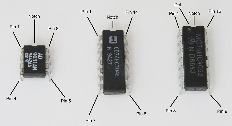
FIGURE 2-45 Integrated-circuit packages for 8, 14, and 16 pins.
The pin-outs for integrated circuits work as follows:
1. Oriented from the top, a small dot or notch faces “north.” Note that the closest pin to the dot is pin 1. Starting from the upper left-hand side of the chip is pin 1; now count one pin at a time in a counterclockwise rotation such that by the bottom of the left column you are at pin 4 for an 8-pin chip, pin 7 for a 14-pin chip, or pin 8 for a 16-pin chip.
2. Continue to count as you go from the bottom left to the bottom right, and continue counting one pin at time to the upper right-hand corner, which is the last pin.
The power applied to the integrated circuit must not be reversed so as to avoid permanent damage. Therefore, it is suggested that you check the pin-out of an integrated circuit twice just to make sure that the power pins are connected properly.
Depending on which integrated circuit you are using, the power pins may be in different locations. Therefore, always download or get a copy of the data sheet for each integrated circuit that you use. For example, in a single op amp such as the LM741, the plus supply is at pin 7, whereas in a dual op amp integrated circuit such as the LM1458, the plus supply is at pin 8.
Also, the plus and minus power pins of all integrated circuits should have small decoupling capacitors about 0.1 μF to each power pin and ground. For example, the LM741 has a plus power pin at pin 7. Connect one lead of the 0.1-μF capacitor to pin 7 and the other lead of the 0.1-μF capacitor to ground. Then locate the minus supply pin of the LM741, which is pin 4. Take a second 0.1-μF capacitor and connect one lead to pin 4 and the other lead of this capacitor to ground.
Connecting decoupling capacitors to the power pins of integrated circuits is necessary to avoid noisy or oscillating signals from the output of the integrated circuit.
Other types of integrated circuits come in TO-92 packages, such as voltage regulators and radio circuits. Also, there are power regulators and amplifiers in the TO-220 case form. These and other integrated circuits will be described in more detail as needed in the subsequent chapters.
Schematic Diagrams
If one wants to communicate the essentials of a circuit, one way is to literally illustrate by hand each component. Alternatively, one can build the circuit in an organized manner in which all the wires and connections are well in view. For simple circuits, one can get away with this technique. In this book, there will be examples where the circuits are photographed. This will allow the reader to see how the parts were assembled. Also included will be schematic diagrams that represent the circuits.
As one builds more and more circuits, eventually she or he will understand a rule of thumb as to how to connect the parts when just following the schematic diagram. Figure 2-46 shows actual components and how they fit within the corresponding schematic diagrams.
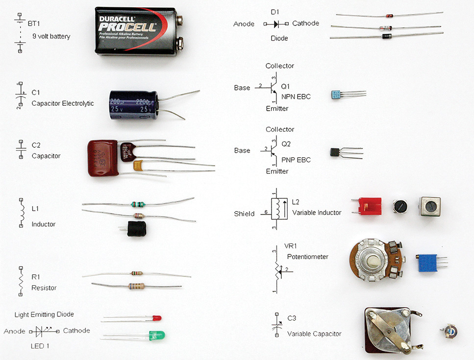
FIGURE 2-46 Some actual components and their schematic representations.
This chapter will introduce the reader to two circuits, a video low-pass filter, and an amplifier. Figure 2-47 shows a video bandwidth low-pass filter, which has two inductors and four silver mica capacitors. The schematic representation of this circuit will evolve from a literally drawn schematic to a more refined version. We will start with Figure 2-48.
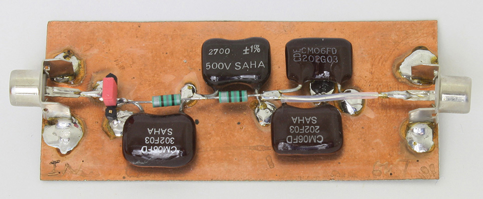
FIGURE 2-47 Video bandwidth low-pass filter.
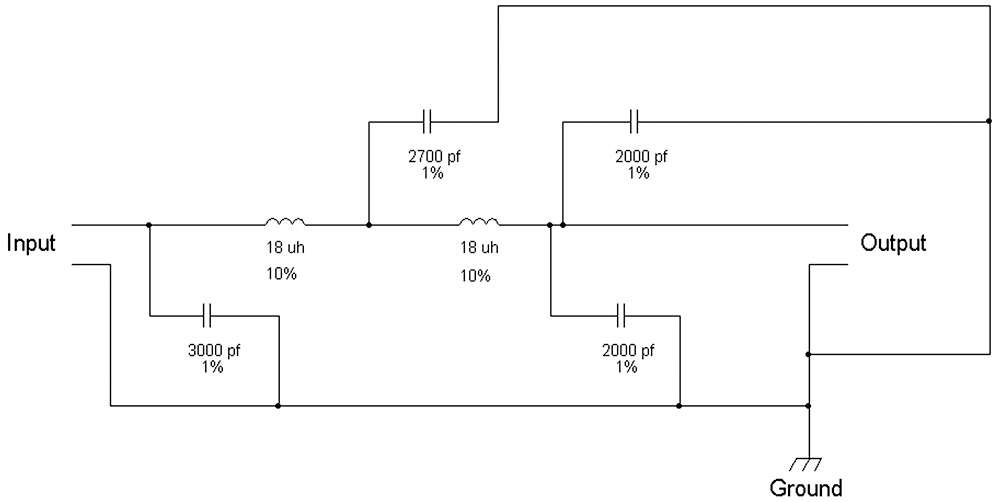
FIGURE 2-48 First rough-sketch schematic of the circuit in Figure 2-47.
After the rough sketch, which looks pretty much like the basic orientation of the parts, we try to further redraw the schematic as shown in Figure 2-49.
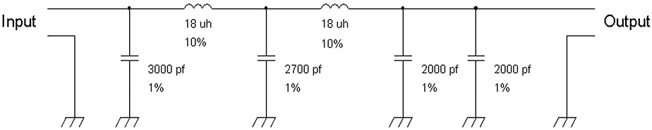
FIGURE 2-49 Redrawn schematic of the video low-pass filter.
However, it would be great to add reference designations to the schematic diagram since there will be at time parts that have the same value. In this case, both inductors are 18 μH. For inductors, we choose L as the designator for an inductor or coil. And for a capacitor, we can take the obvious letter C. See Figure 2-50.
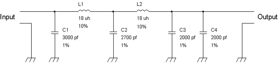
FIGURE 2-50 Schematic of the video low-pass filter with reference designations.
Finally, we can reduce the amount of information on the schematic and move that information elsewhere. For example, since all capacitors are 1 percent and all inductors are 10 percent for the schematic, we can just draw the component, its reference designation and value (e.g., C1 3,000 pF), and other pertinent information can be footnoted outside the schematic diagram (see Figure 2-51). This figure shows the result after a few iterations from the original rough-sketch schematic.
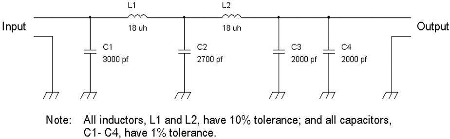
FIGURE 2-51 Schematic of the video low-pass filter with footnotes.
We can draw this schematic with a computer-aided design (CAD) program such as the free ORCAD Capture Lite (version 16.x), which is downloadable at www.cadence.com/products/orcad/pages/downloads.aspx. Alternatively, you can also download LT SPICE from Linear Technology at www.linear.com/designtools/software/. However, for the reader, it may be easier to keep a notebook and draw the schematics by hand. Using a CAD schematic program is a learning process that can take some time to master.
For the second example, Figure 2-52 shows the one-transistor amplifier from Chapter 1.
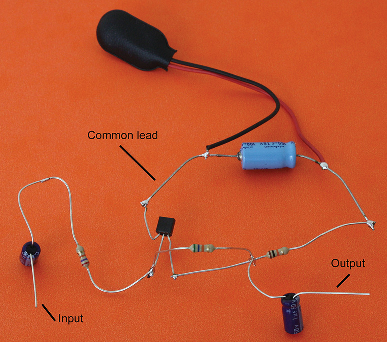
FIGURE 2-52 A one-transistor amplifier circuit.
Figures 2-53 through 2-55 show how schematic drawings are improved from one iteration to another. Figure 2-53 shows the circuit with no ground yet. However, it points out the common lead or common wire that may be construed as a (chassis) ground. The “final” schematic is not really the last one. A different person may have another way to redraw it. But this schematic is close enough for accurate documentation.
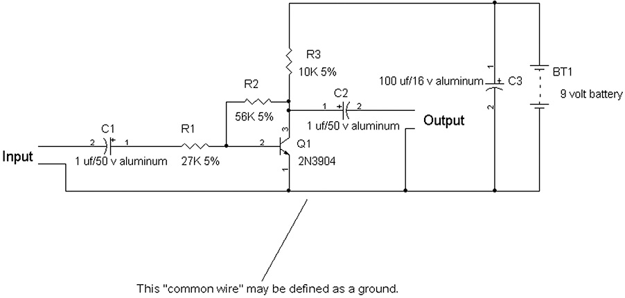
FIGURE 2-53 First schematic diagram of the one-transistor amplifier shown in Figure 2-52.
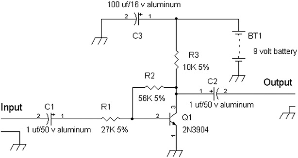
FIGURE 2-54 Schematic diagram further refined to show a ground symbol to replace the common-wire lead. The schematic looks a bit less cluttered.
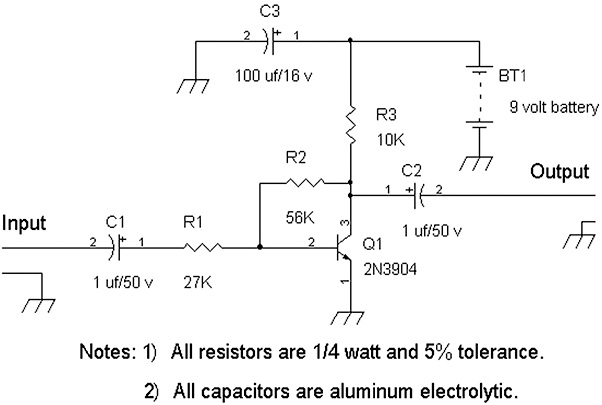
FIGURE 2-55 “Final” iteration of the one-transistor amplifier schematic.
NOTE Other electronic components such as variable inductors, variable capacitors, and variable resistors or potentimeters will be covered in the later chapters. For now, this chapter has covered the basic components for simple projects and experiments.
References
1. Robert L. Shrader, Electronic Communication. New York: McGraw-Hill, 1967.
2. Mouser Catalog, www.mouser.com.
3. “Eveready Battery Applications and Engineering Data,” Union Carbide, Bound Brook, NJ.
4. Jameco Catalog, www.jameco.com.
5. RadioShack, Enercell Battery Guidebook, 2nd ed. Niles, IL: Master Publishing, 1990.
6. Digikey Catalog, www.digikey.com.
7. “Triode,” wikipedia.org.
8. “Tetrode,” wikipedia.org.
9. “Pentode,” wikipedia.org.
10. “Vacuum tubes,” wikipedia.org.