
CHAPTER 3
![]()
Construction Techniques and Simple Test Equipment
In this chapter, we will look at a few different types of circuit construction techniques. With the overview of certain electronics components introduced in Chapter 2, this chapter will show how they can be assembled to make a useful circuit.
For starters, solder-less circuits will be examined such as superstrip prototype boards or circuits assembled via twisting the wire leads and taping down the components onto an index card. Alternatively, a giant loopstick antenna coil radio is shown to work even though the wires leading up to the tuning capacitor are at least a foot long. Later we will cover assembling circuits via soldering. There will be examples of soldered circuits in copper-clad and vector boards. Also, did you know that it is possible to solder electronic components that hang in thin air and still work? A first project is included at the end of the chapter that shows how to make a simple battery tester.
Solderless Circuit Construction Techniques
Let’s Do the Twist—Twisting Wires to Build Circuits
The easiest way to confirm whether a circuit works or to build a temporary circuit is to use just wires twisted together. Figure 3-1 shows the schematic diagram and Figure 3-2 shows the prototype circuit. There are three resistors, which are 20 kΩ 5 percent resistors (red-black-orange-gold), a precision 10 kΩ 1 percent resistor (brown-black-black-red-brown), and a 12 kΩ 5 percent bridging resistor (brown-red-orange-gold).
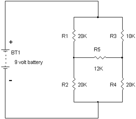
FIGURE 3-1 Schematic diagram of a five-resistor circuit.

FIGURE 3-2 Solderless prototype build on an index card.
This resistor network has a 9-volt battery for its power source. The object is to find the voltage across R5, the 12 kΩ resistor. One way to find out is to measure the voltage, which was found to be 0.633 volt across the 12 kΩ resistor with the 9-volt battery measuring 9.24 volts. The other way is to calculate the current flowing through the 12 kΩ resistor. For now, it’s easier to do a direct measurement than to go through the pain of circuit analysis. Normally, the circuit would be analyzed with five equations. However for the advanced readers, by using Thevenin equivalent circuits that are mentioned in Chapter 15, this circuit is simplified to one equation. The general answer is the current, IR5, flowing through R5 from left to right is:
IR5 = BT1{[R2/(R1 + R2)] – [R4/(R3 + R4)]}/[R1||R2 + R5 + R3||R4]
My previous book, Build Your Own Transistor Radios (McGraw-Hill), shows a detailed analysis of converting a bridge circuit to a simpler one.
Note that the construction of this circuit is relatively easy, just requiring adhesive tape (e.g., transparent, packing, masking, or duct tape) and an index card or even a piece of paper or cardboard. One advantage of this type of construction is fast verification of simple circuits, say, fewer than 20 components, depending on the size of the index card or cardboard. However, including integrated circuits into this type of prototyping technique is difficult because of their short leads. Most through-hole lead semiconductors will work fine, including transistors, light-emitting diodes (LEDs), photodiode, diodes, and rectifiers. Even vacuum tubes inserted into sockets will work with this approach.
Let’s now look at an extreme radio circuit put on a 24 inch by 36 inch piece of drafting paper. All of the connections are twisted together. Figures 3-3 and 3-4 show the schematic and prototype. Note in Figure 3-4 the size of the antenna coil (top of the figure) in comparison with the AA battery on the bottom left and the tuning capacitor on the bottom right.
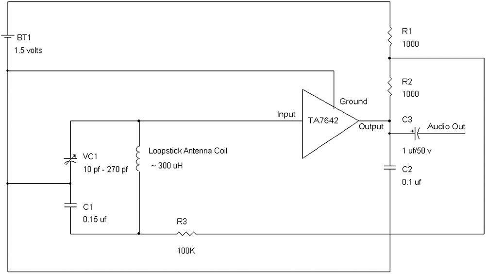
FIGURE 3-3 Schematic of a tuned radio-frequency (RF) radio using a 30-inch (2½-foot) loopstick antenna coil.
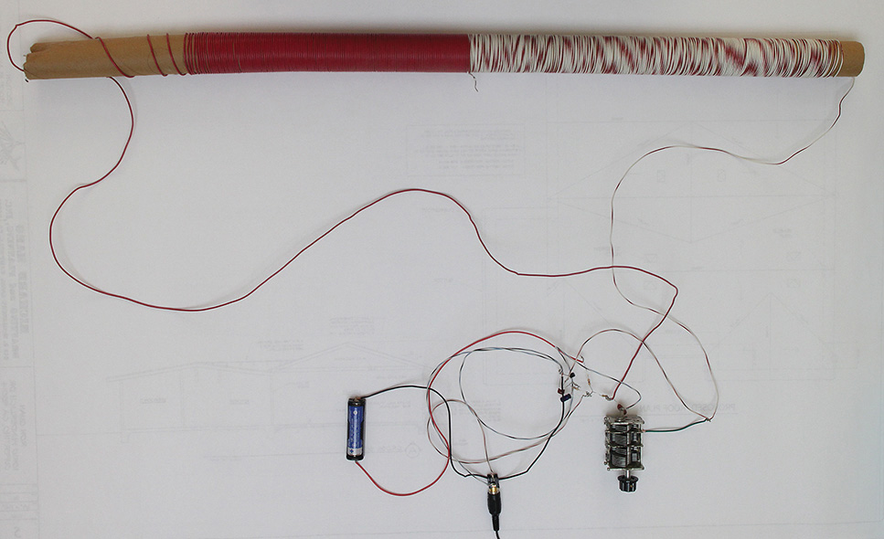
FIGURE 3-4 Extreme radio built with a 30-inch antenna coil with wires exceeding one foot.
Believe it or not, this radio actually works. It pulled in about seven to nine AM radio stations. However, I would not recommend building radios with lead lengths this long. This extreme radio was built to show that one can get away at times with ridiculously long wire lead lengths and still have a working circuit.
When building prototypes, one may ask, “Will the circuit still work if the wire leads are long?” The answer is that generally anything working at under 2 MHz (AM band or below) can tolerate long leads and will still work. However, keeping lead lengths less than a few inches long is a general rule of thumb. For circuits working at higher frequencies or for avoiding picking up extraneous noise (e.g., 50 or 60Hz hum), one should build circuits with leads that are less than an inch or half an inch long.
Knock on Wood—A Wooden Breadboard
Putting circuits onto a piece of wood is one of the oldest ways to construct electrical or electronic circuits. This method can be seen in books dating back to the nineteenth century with the advent of the incandescent light bulb, batteries, the telegraph, and the telephone. Radios in the early 1900s using coherers and later galena crystals were routinely built on wooden platforms or just on slabs of wood. Now see Figure 3-5. In this example, #6 and #4 sheet metal screws are fine for fastening the Fahnestock clips. These clips are often used as input, output, and power-supply terminals. To assemble a circuit, the #6 screws are used as anchor points or for mounting the clips onto the wood. I drilled with a 7/64-inch drill bit to allow easier installation of the screws. Note that Fahnestock clips can be purchased on Amazon (www.amazon.com) and other sites on the Web. Figures 3-6 and 3-7 show a wooden breadboard and a schematic for a photodiode and LED circuit. When light hits the photodiode, the LED turns on.
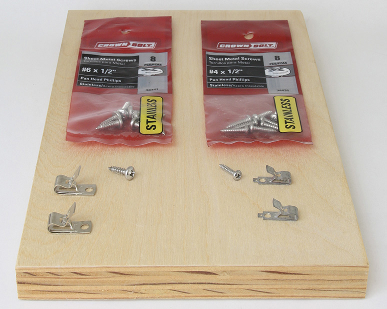
FIGURE 3-5 Wooden breadboard using Fahnestock clips and screws.

FIGURE 3-6 Schematic of a photodiode and LED circuit.
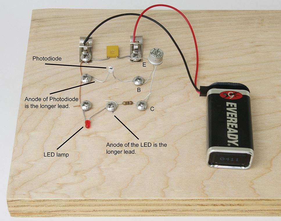
FIGURE 3-7 A wooden breadboard for the photodiode and LED circuit.
Figure 3-7 shows how a resistor, capacitor, transistor, LED, and photodiode are mounted on a wooden board. The #6 screws anchor the parts, and the Fahnestock clips provide the power terminals for the 9-volt battery. As seen in this figure, the parts are put in a north-south-east-west structure. That is, the parts are preferably oriented at 90-degree angles, although at times diagonal orientations may be fine. Transistor Q1 may be a silicon transistor such as the 2N2905, 2N5087, or 2N3906 or even an old PNP germanium transistor, as shown in Figure 3-7. Note that the transistors today have shorter leads for the emitter (E), base (B), and collector (C).
NOTE Be sure that the photodiode and LED are connected correctly. When a photodiode or LED is purchased, there are two leads—the anode and the cathode. The anode’s wire is always the longer lead that comes with a photodiode and an LED, while the cathode’s lead is always the shorter wire in the photodiode and LED.
Generally, the wooden breadboard is not used except for nostalgic purposes. This type of breadboard is used often for crystal radios, telegraphs, or electricity experiments. One advantage of constructing circuits on a piece of wood is that the stray capacitance is low. However, the disadvantage is that the wiring is generally longer than when a circuit is constructed on copper-clad or vector boards.
Superstrip Prototype Boards
This is probably the most popular method of building circuits today. No soldering is needed, and the circuits can be quickly assembled and evaluated. The superstrip board has rows of connections conveniently spaced at 100 mils (0.100 inch), which accommodates through-hole integrated circuits. Many of these types of boards can be purchased with binding-post connectors for hooking up one or more power supplies, and precut wires may be bought as well. Generally, insulated wires are used [e.g., 22 or 24 American Wire Gauge (AWG)], and preferably the insulation is removed by about ¼ inch. However, precut wires with pins on each end for the superstrip board can be purchased as well. See Figure 3-8.
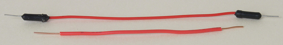
FIGURE 3-8 Precut wire with pins on each end and 22 AWG solid wire.
There are many sizes of superstrip boards to choose from, including the board shown in Figure 3-9. This board is actually split into four independent sectors, which allows prototyping of four independent circuits with separate positive (+) and negative (–) power-supply buses. Each section has its own (–) and (+) power rails to the left and right of the main sections A to E and F to J as seen at the bottom of the figure. To connect the power rails for sections 1 and 2, jumper wires are required (see Figure 3-9).
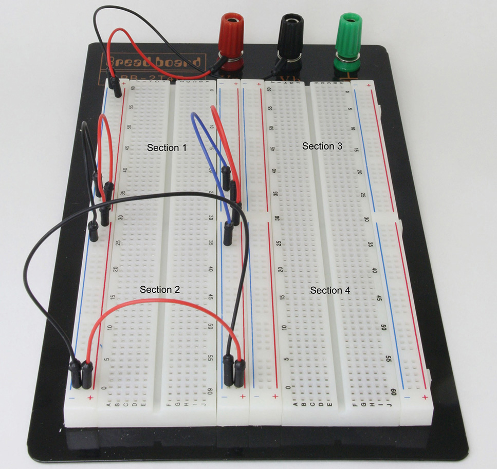
FIGURE 3-9 Interconnecting power-rail buses for sections 1 and 2.
By interconnecting the (–) and (+) buses around “30,” sections 1 and 2 now have power rails for the plus and minus supplies going down the whole left section of the prototype board. By further connecting (–) and (+) wires at “0” and “60” in the lower-left portion of the board, the plus and minus supplies are connected at both the left and right portions of the left-hand superstrip prototype board sections 1 and 2. Figure 3-10 shows a schematic of the one-transistor amplifier from Chapter 2, and Figure 3-11 shows an example of the one-transistor amplifier assembled on a superstrip board.
FIGURE 3-10 Schematic diagram of the one-transistor amplifier featured in Figure 2-52.
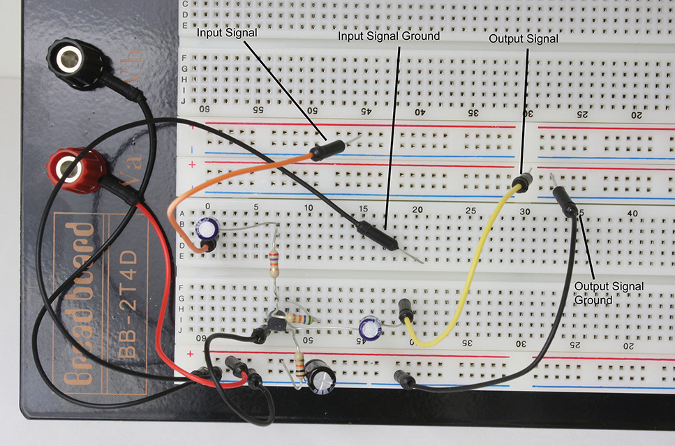
FIGURE 3-11 One-transistor amplifier assembled on a superstrip prototype board.
In this circuit, there is only a single supply, so the (–) supply is ground, and the (+) supply is +9 volts. Thus the two binding posts, Va for (+) and Vb for (–), are connected to the plus and minus buses of the board.
For another example of using the superstrip prototype for constructing an integrated-circuit (IC) audio amplifier, see Figure 3-12 for the schematic and Figure 3-13 for the assembled circuit. In this circuit, a smaller superstrip prototype board is used. The LM386 integrated circuit is inserted as shown. Pin 1 of the LM386 is connected to “10e to 10a,” and pin 8 is connected to “10f to 10j” of the prototype board.
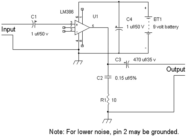
FIGURE 3-12 Schematic of LM386 integrated-circuit audio amplifier.

FIGURE 3-13 Audio amplifier prototype.
This audio amplifier should have worked on this prototype board but instead had problems with parasitic oscillations. The capacitances between the adjacent rows, such as rows 11 and 12 or rows 12 and 13, caused the LM386 to operate in an unreliable manner. Therefore, it is not recommended to the reader that this circuit be built with this type of prototype board. It was found later with other types of methods, such as vector board or three-dimensional (3D) wire constructions, the LM386 operated properly without oscillations.
The superstrip board in general is fine for low-frequency circuits generally less than 2 MHz. I would not recommend using it for radio circuits. The parasitic or stray capacitances between the rows are sufficient to throw off the performance of radio-frequency (RF) circuits.
For certain audio applications and low-power circuits of less than half a watt (< 0.5 watt), this board is okay. Just be aware that if one builds a circuit on this board and it does not quite perform to expectations, the hobbyist should try a different construction technique, such as using vector or copper-clad boards, which generally require some soldering.
Soldering Tools
In general, soldering is a way of making a breadboard more permanent compared to super-strip boards. By soldering, the circuit can be transported without fear that the connections will come loose or fall off.
The most commonly used soldering tool is the soldering pencil. It is light and can be more precisely manipulated into tight locations of the circuit board than using a soldering gun. Because it is lighter than a soldering gun, it causes much less fatigue than holding a soldering gun over a long period of time.
Generally, for small circuit boards, a 25 watt to 35 watt soldering pencil will do. For soldering more than just capacitors, resistors, inductors, small transistors, etc., a 45 watt soldering pencil allows reliable soldering to electronic parts that soak up the heat, such as open-frame variable capacitors, large power resistors, and mounted electrolytic capacitors for power supplies. Soldering pencils have replacement tips, which can be the conical or flat-blade chisel types. See Figure 3-14.
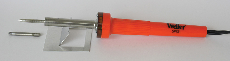
FIGURE 3-14 A Weller SP-23L soldering pencil with extra tip and holder.
In the figure, the soldering pencil is resting on a soldering pencil holder to keep the tip from inadvertently moving around or from moving away. The holder is used so that the tip does not accidentally heat another object that can cause a fire or injury.
NOTE For safety reasons, always rest the soldering pencil on a holder.
For the general method of soldering, normally, the lead or connector is heated with the soldering tip, and solder is added such that the heated lead or part melts the solder. This is the standard way that soldering is taught. However, I have found that placing the solder tip over the solder to melt the solder onto the wire and then moving the solder tip to heat the wire will produce a satisfactory solder joint.
Another type of soldering pencil includes a solder station, such as the one shown in Figure 3-15. The sponge normally holds some water to keep it moist so that the hot tip can be cleaned from time to time. Every now and then while soldering, the tip will accumulate dirt or other types of debris, which can be cleaned off by wiping the hot tip on the wet sponge.

FIGURE 3-15 A solder station with a holder and sponge.
Note that the AC power plug is three pronged with a ground plug. This means that if your circuit is still on, the tip of this soldering pencil that is soldering a part in the circuit will cause a short to ground. Therefore, be sure to turn off your circuit before you do some soldering on it. However, the tip of the soldering pencil can be isolated from ground with a 120-volt three-pin-to-two-pin ground-isolation adapter.
At this point, what type of solder is suitable? For electronics work, use rosin-core flux solder. There are other types of solder, such as bar solder, solder without flux; and then there’s acid core solder, normally used for plumbing or pipes, which should never be used in electronic circuits.
Solder with a composition of 60 to 63 percent tin and 40 to 37 percent lead usually works best. For large jobs, the diameter of the solder can be on the order of 0.062 inch to 0.080 inch. Normally, solder of this diameter is used for large wires, cables, or electronic components. For most electronic circuits, tin-lead (Sn-Pb) rosin solder with about a 0.032-inch diameter should work fine. See Figure 3-16.
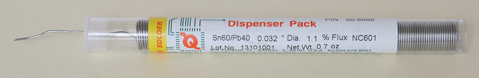
FIGURE 3-16 A tube of 0.032-inch-diameter tin-lead rosin solder.
Tin-lead rosin-core solder is the preferred type for electronics work. There are other types, such as lead-free and 2 percent silver solder, but both are not recommended. Lead-free solder tends not to flow as well as the tin-lead solder, and 2 percent silver solder is expensive and does not have any significant advantage for general electronics work. Therefore, I would just recommend using 60/40 or 63/37 tin-lead rosin-core solder. Also note that solder can be bought in the ½ or 1 pound spool.
NOTE Before shutting off a soldering pencil or gun, melt some solder onto the tip to prevent the tip from oxidizing or corroding. If the tip is oxidized, let the tip cool, and use fine sandpaper or emery cloth to remove the oxidation. Then turn on the soldering pencil or gun and melt some solder on the tip.
What if too much solder is applied, and there is a short circuit between connections? Is there a way to clear or remove the short circuit? Yes, there is a way to clear the excess solder by using a desolder pump. Alternatively, one can use bare copper braided meshed wire to soak up the excess solder and clear the short circuit. See Figure 3-17.
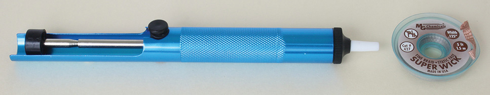
FIGURE 3-17 Desoldering pump for vacuuming excess solder and flat braided wire (Super Wick) for removing solder.
This desoldering pump has a trigger button shown in the middle of it. The desoldering pump must be loaded by compressing the plunger. Once loaded, place the tip of the pump in the desired location to remove excess solder. Then use a soldering pencil to heat the excess solder, and depress the trigger button of the solder pump to suck out the excess hot solder.
To remove solder using the “Super Wick,” place the braided wire over the location of the excess solder. Use a soldering pencil to heat up the braid so that the excess solder flows into the braided wire. Remove the braided wire while the solder is still hot, and the excess solder should be cleared. If not, repeat the process with a clean patch of the braided wire. If there is a great amount of solder that is shorting the connections, a desoldering pump is preferred.
The Art of Pre-Tinning Wires or Connections
Sometimes it’s hard to find a “third hand” while soldering two pieces of wire or connections together. Ideally, one makes a mechanical fit between the two connections by wrapping or bending the leads together. However if this is not possible, then pre-tinning the wires is a good practice. Actually, in general pre-tinning wires or connections should be done whenever possible.
Figure 3-18 shows an example of pre-tinning leads. By using one hand to hold the electrolytic capacitor and the other to hold the soldering pencil, the negative lead of the capacitor is pretinned.

FIGURE 3-18 Pretinning wires using two hands.
When two different leads are pretinned, one can then solder the two leads without having to feed solder. Once the two leads are secured mechanically, one can touch up the connection with a little extra solder.
Examples of Various Solder Joints
Figure 3-19 shows a series of nine solder joints on a copper-clad board. Solder joints numbered 1, 2, 3, and 5 are unreliable. Joints numbered 1 and 2 are cold solder joints that have the solder dabbed onto the copper instead of the solder melting and adhering to the copper for reliable electrical conduction. Solder joints 3 and 5 lacked sufficient heat and did not adhere to the copper very well. A telltale characteristic of soldering with insufficient heating is sharp or jagged edges on the solder joint.
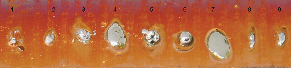
FIGURE 3-19 Examples of cold and good solder joints.
Soldering examples from numbers 4 and 7 show good solder joints, with the solder adhering well to the copper. Solder joints number 6 shows a bubble or beading on the surface of the copper, which does not bond to the copper with a good electrical connection. Joints numbered 8 and 9 may work, but more solder should have been used.
Prototype Circuits via Soldering
An example is a 3D breadboard of the circuit shown in Figure 3-13. Recall that using the superstrip prototype board that inherently has parasitic capacitances led to unreliable operation of this audio amplifier. Figures 3-20 and 3-21 show the schematic and the 3D wired prototype circuit. In Figure 3-21, we start with the LM386 integrated circuit placed upside down. With the (upside down) LM386’s notch or dot pointing north, pin 1 starts at the upper righthand side (RHS), and the pins counts downward in a clockwise manner. Note that when the LM386 (or any 8 pin IC) is placed right side up and viewed from the top, pin 1 starts from the upper-left side and increments via a counterclockwise rotation.
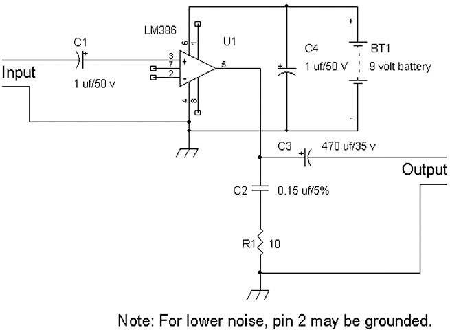
FIGURE 3-20 Schematic of the LM386 audio amplifier.
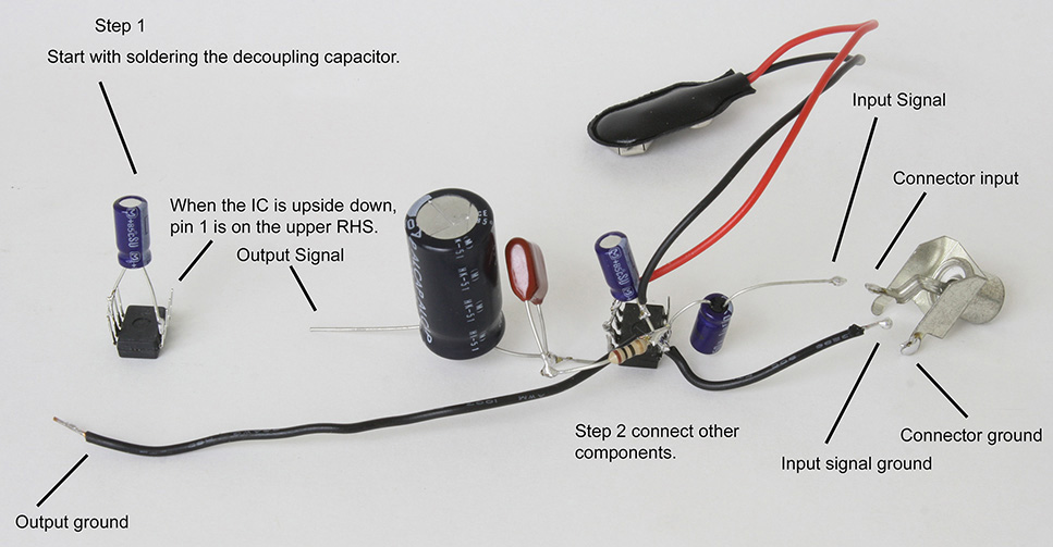
FIGURE 3-21 Prototype circuit wired in a 3D manner.
First, solder the decoupling capacitor, with the negative terminal of the electrolytic capacitor soldered to pin 4 and the positive terminal of the capacitor soldered to pin 6 (see the left side of Figure 3-21). Then, as shown on the right side of the figure, add the 9-volt battery-connector lead, with the red positive lead soldered on the decoupling capacitor’s positive lead and the black lead of the 9-volt battery connector soldered to the negative lead of the decoupling capacitor. Then start soldering the other parts as shown, such as the input and output capacitors, and observe the polarities of these capacitors as well. Finally, Figure 3-21 also shows examples of pre-tinning the input signal/ground leads and the input connector.
This amplifier as shown worked reliably and well. Who would have figured that a messy 3D prototype circuit can sometimes work better than a neatly assembled circuit on a superstrip board? But this happens often. The 3D circuit has minimal parasitic capacitances as one of its advantages over the superstrip board.
One of the first soldered prototype circuits was introduced in Chapter 2 as the one-transistor amplifier (Figures 3-22 and 3-23). This circuit is another example of a 3D prototype. Constructing a soldered prototype in this way provides a quick way to verify that the circuit works. Normally, the leads of the components do not need to be trimmed. Full-length leads can be used for circuits operating below 2 MHz. If the leads of the components are cut short (<½ inch), this type of 3D prototype circuit will work at much higher frequencies (up to at least 10 MHz).
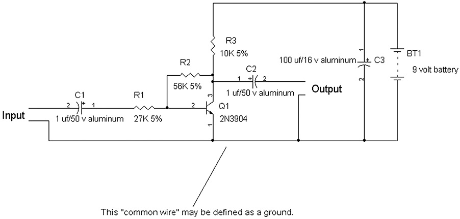
FIGURE 3-22 Schematic of a one-transistor amplifier.
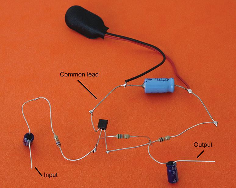
FIGURE 3-23 A 3D circuit of a one-transistor amplifier.
Another way to construct the one-transistor amplifier is to solder the parts on a piece of blank copper-clad printed circuit board. This arrangement is more permanent (see Figure 3-24). Blank copper-clad boards are common, and they can be bought on the Web or at an electronics hobbyist’s store. Normally, I use copper-clad boards that are 22 mils to 32 mils thick, single or doubled sided. This allows using a pair of medium-sized scissors to cut them. For boards that are up to 50 mils thick, I use metal cutting shears. Beyond 50 mils, one usually has to use a saw or score the board with an Exacto knife or equivalent and then break off the piece of copper clad board.

FIGURE 3-24 Copper-clad prototype version of a one-transistor amplifier shown in steps from left to right.
In Figure 3-24, we start with step 1 by placing the transistor on the board and identifying the emitter (E), base (B), and collector (C) by placing the 2N3904 transistor flat side up. In step 2, you know that the emitter is tied to “common,” so we will use the copper as the common, ground, or ground plane. Therefore, the emitter of the 2N3904 is soldered to the copper ground plane. We also will need a decoupling capacitor, and thus its negative terminal is also soldered to the ground plane. Again, observe the polarities of electrolytic capacitors.
Using the positive terminal of the decoupling capacitor as a convenient support, solder one lead of the 10 kΩ resistor (brown, black, orange, and gold bands) to it, and solder the second lead of the 10 kΩ resistor to the collector of the 2N3904 transistor. Also, you can now solder in the two other resistors, a 56 kΩ resistor (green, blue, orange, and gold bands) across the collector and base of the transistor and one lead of the 27 kΩ (red, violet, orange, and gold) input resistor to the base of the transistor. See step 3 in Figure 3-24.
Finally, in step 4 we add the input and output capacitors and RCA phono jacks (left to right) and the 9-volt battery connector. To avoid the battery leads from coming off if the circuit is flexed too often, we add a resistor that goes to nowhere, with both leads soldered to ground to anchor the battery clip’s two power leads.
Vector or Perforated Boards
For building with integrated circuits (ICs), the vector board often is a perfect way to mount them. Vector or perforated boards come with 100-mil spacings and thus allows easy installation of integrated circuits, certain connectors, etc. The leads of ¼ watt resistors can be bent to a 400- mil or 500-mil spacing. Radial-lead capacitors are often made with 100-mil spacings or multiples thereof, such as 200 mils, 300 mils, etc. See Figure 3-25.

FIGURE 3-25 A perforated board without solder pads and one with solder pads on one side.
Certain vector or perforated boards have solder pads on one side or solder pads on both top and bottom sides, and some of the more expensive ones have a ground-place mesh on one side. However, for most hobbyists, a perforated or vector board without the solder pads is more commonly used.
Building the LM386 Audio Amplifier on a Vector Board
For this circuit, a vector board without solder pads is chosen. To allow for flexibility, an 8-pin socket is used for the LM386. Instead of soldering the integrated circuit (IC) into the vector board directly, a socket allows changing the IC just in case there is a problem, such as a blown chip. Because there are no pads on the vector board to solder on, the socket is taped onto the board, and the power-supply decoupling capacitor is placed close to the socket. The socket has a notch, which is normally pointed north. Figures 3-26 and 3-27 show the schematic and the vector board.

FIGURE 3-26 Schematic diagram of the LM386 amplifier.
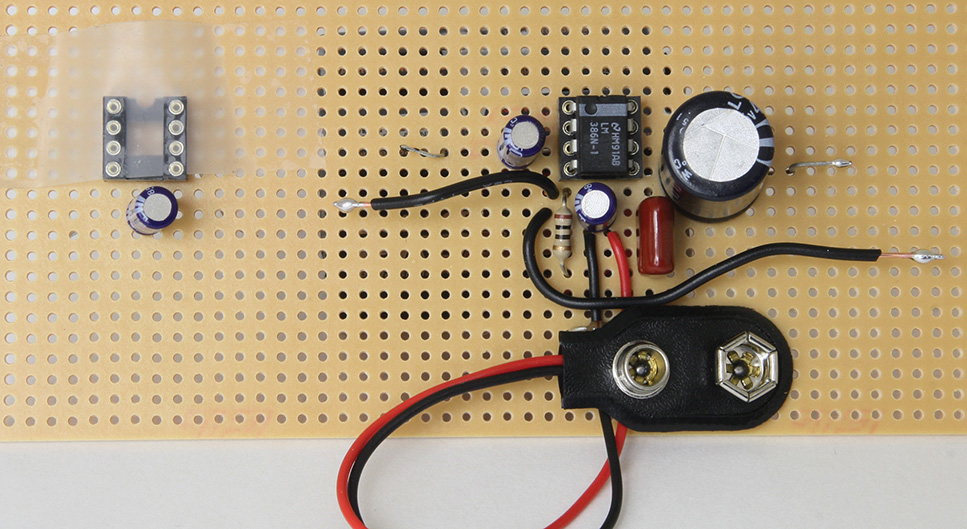
FIGURE 3-27 Vector board first try. The IC socket is taped to the board.
On the left, the IC socket is taped to the vector board for an initial step in the construction. An electrolytic capacitor is placed near pins 4 and 5 of the IC socket. The socket is oriented to point its notch up or north. On the right side is a completed version of the audio amplifier, which works fine. Figure 3-28 shows the underside of the vector board. Once the decoupling capacitor’s leads are soldered, the socket is secured to the vector board, which means that the tape on the top side can be removed, and the other parts may be installed and soldered to the other pins of the socket.

FIGURE 3-28 Bottom side of the vector board showing the decoupling capacitor’s leads to be soldered at pins 4 and 6 of the IC socket.
There are times when the battery can be reversed by accident, which can cause permanent damage to the LM386 chip. To prevent any momentary reversal of supply voltage into the IC, a protection diode (e.g., 1N4001-1N4005) is placed such that the cathode of the diode is connected to pin 6, the (+) supply terminal, and the anode of the protection diode is connected to pin 4, the (–) or ground pin of the LM386. Figure 3-29 shows the improved circuit with reverse battery protection, and Figure 3-30 shows the schematic diagram. Recall that the diode has a band on its body to denote its cathode.
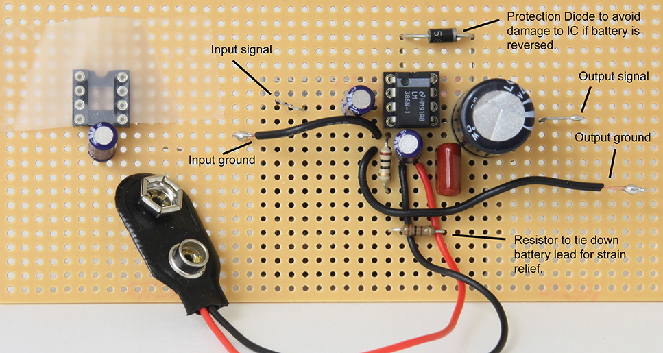
FIGURE 3-29 Completed LM386 audio amplifier with a protection diode to avoid accidentally damaging the IC.
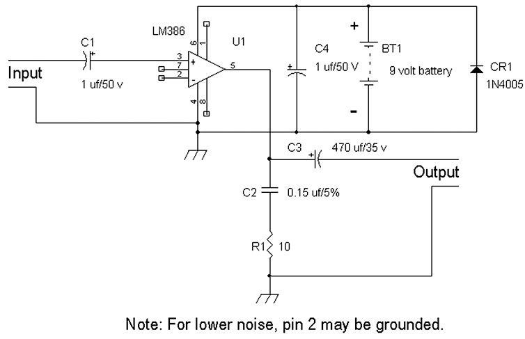
FIGURE 3-30 Schematic diagram of the LM386 amplifier with CR1 a 1N4005 rectifier/diode for reverse battery protection.
As shown in the previous examples, different types of prototype constructions have advantages and disadvantages. For quick verification, the 3D and superstrip prototype methods work fairly well. For high frequencies, building on copper-clad boards is preferable. And for building something a little more permanent, a vector board is a good choice.
When the hobbyist starts building circuits or systems, eventually, the hobbyist, she or he, will begin to see a pattern such as starting with placing the decoupling capacitors near a chip or a main power-supply line. Eventually, a part of the circuit is memorized by she or he, and the hobbyist need not look at every part and connection one at a time to build the circuit. That is, a portion of the schematic is visualized in the hobbyist’s head. Once the hobbyist has built maybe a dozen circuits, other skills will fall into place, such as remembering part of the resistor color code for often-used resistors. As I have mentioned to some people, building circuits is sort of like the way we learned to first copy a word letter by letter, then in groups of letters, and then finally just looking at the word and writing it down because we have learned that word. Eventually, an experienced hobbyist will be able to build circuits by soldering a few components at a time before looking at the schematic to connect the next few parts.
For building complicated circuits with many parts, one way to keep track of what has been wired or soldered is to make a copy of the schematic. Then, as the circuit is being built, use a yellow, green, or red highlighter (marker) to check off or to highlight over the area of the schematic that has been built.
Simple Test Equipment: Battery Testers and VOMs
In terms of a simple piece of test equipment, a battery tester is a prime example. An ideal voltmeter measures the voltages of circuits or batteries and draws very little current from the circuit or battery it is measuring. For testing batteries, we are interested really in one characteristic—what is the battery voltage tested under load? By load, we mean that batteries normally provide power to lamps, radios, motors, and other devices. These devices draw current.
A battery tester is a voltmeter that also includes a load, which is a resistor to draw current that is typical of a device’s power consumption. For example, in flashlights, the typical current draw is between 250 mA and 1000 mA. And the current drain for radios ranges from about 10 mAto 100 mA.
Any battery can be modeled or characterized as a perfect voltage source V with an internal series resistance R_internal_series. As the battery is being used, the battery voltage V drops, and the internal series resistance R_internal_series increases. See Figure 3-31).
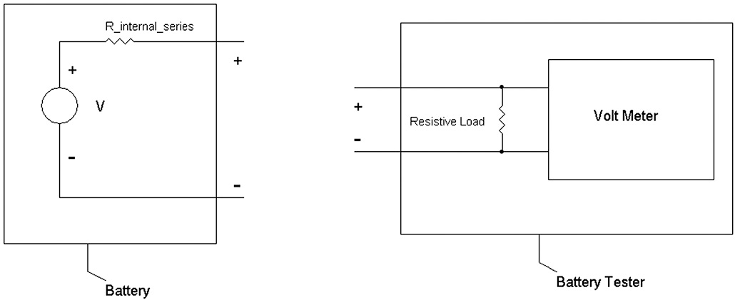
FIGURE 3-31 Model of a battery (left). Block diagram of a battery tester (right).
An older battery tester (Eveready) is shown in Figure 3-32, and it has a selector switch for testing different types of batteries made for high and low current drains. This includes for testing at high currents that simulate the load from flashlights and testing at lower currents typical of the current draw from radios. This battery tester also measures the performance of photoflash batteries under “1.5 V PHOTOTEST FOR AN INSTANT ONLY.” Dating back to at least the late 1950s, special batteries with higher current output (e.g., lower internal series resistance R_internal_series) were manufactured. I remember that these photoflash carbon batteries were available in D and AA sizes. The higher output current was needed to ensure that flashbulbs were ignited reliably. However, these types of batteries were discontinued with the advent of inherently high-current alkaline batteries.
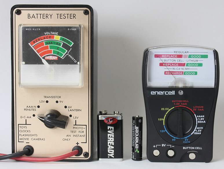
FIGURE 3-32 An older type (“Eveready”) battery tester from the 1960s or 1970s (left), and a newer type (RadioShack’s Enercell) battery tester from 2013 (right).
For this older type Eveready battery tester in Figure 3-32, we shall only concern ourselves with the tester’s selector switch, set at the D-C-AA for toys, clocks, flashlights, and movie camers. Yes, in the old days, before video recorders, people shot 8-mm or super 8-mm home movies on film. The other selection we will concern ourselves with is the 1.5-volt and 9-volt setting for “transistor,” meaning for use in transistor or solid-state radios (as opposed to the really old vacuum-tube portable radios).
Before we look at how this battery tester works, I tested three 9-volt carbon batteries (all of them had been used to some degree). See Table 3-1 for a summary.
TABLE 3-1 Test Results for Three 9-Volt Carbon Batteries Using the Older Eveready Battery Tester In Figure 3-32

From Table 3-1, we see that as the battery is being more and more used up, the voltage drops, and the internal series resistance increases. In general, the voltage will drop a little, as evidenced by looking at samples 1 and 2 with voltages of 9.24 volts and 8.90 volts (showing a 3.7 percent drop), while the internal resistance increases dramatically from 42 ohms to 445 ohms, an increase of over 10 fold or over a 900 percent increase.
NOTE Chapter 15 will explain Thevenin series resistances, which may be used for describing the internal resistance of batteries.
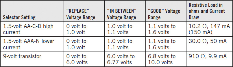
Now let’s go back and analyze the battery tester. With a power supply, I found the voltage ranges for “REPLACE,” “IN BETWEEN,” and “GOOD.” Also, with an ohmmeter, I measured the resistive load of the battery tester for 1.5 and 9 volts. The results are shown in Table 3-2, which also includes the current draw from the battery tester based on the nominal voltages of 1.5 and 9 volts. The current draw is calculated by Ohm’s law. That is, I = V/R, where R = resistive load, and V = nominal voltage of a fresh battery, either 1.5 or 9.0 volts. For example, the current draw for a 1.5-volt battery with a 3 Ω load is I = V/R = 1.5 volts/3 Ω = 0.50 amp = 500 mA.
TABLE 3-2 Voltage Ranges for “GOOD” to “REPLACE” Resistive Loads and Current Draws for the Various Settings for the Older Eveready Battery Tester Shown in Figure 3-32

For 1.5-volt batteries, about 0.9 volt has been a historical cutoff voltage for a battery that is considered no longer good, which includes the “IN BETWEEN” range. At 0.90 volt, most flashlight bulbs or toy motors will operate very dimly or run very slowly. Batteries that measure above 0.90 volt and typically at 1.2 volts or more will be deemed good or sufficient to power a device.
Prior to the introduction of LED flashlights, when incandescent lamps were used, the nominal current draw from a two-D-cell flashlight with a PR-2 bulb was about 500 mA. Ergo, the Eveready battery tester via data from Table 3-2 has a 3 Ω resistive load for a nominal drain of 500 mA for a “fresh” 1.5-volt flashlight battery.
The 9 volt battery’s usable performance has a cut-off voltage at about 6 volts. This was based on that by the time the 9-volt battery dropped to 6 volts, a radio was probably not playing very loudly anymore. If one looks carefully, the cutoff voltage is about 66 percent of the nominal voltage for both 1.5-volt and 9-volt batteries. That is, it’s about 1.0 volt for the 1.5-volt battery and about 6 volts for the 9-volt battery.
For assessing what constitutes a GOOD or REPLACE rating, the actual voltage range and resistive loads are based on a judgment call. Other battery testers will have different ranges and load resistances. For example, available in the year 2013 is a RadioShack Enercell battery tester, as shown in Figure 3-32, that has a different take on the performance of batteries by testing batteries at lower currents. For instance, the highest current tested for 1.5-volt batteries is 150 mA versus 500 mA with the older battery tester. Also see Table 3-3 and compare it with Table 3-2 in terms of load currents and what voltages constitute “REPLACE” and “GOOD” readings on the meters.
TABLE 3-3 Voltage Ranges for GOOD to REPLACE, Resistive Loads, and Current Draws for the Various Settings for Testing Batteries of the Newer RadioShack Enercell Battery Tester Shown in Figure 3-32
Using a Standard Volt-Ohm-Milliamp Meter (VOM) as a Battery Tester
We shall look at the VOM’s voltage measuring capability and using it as a battery tester. Typically, digital VOMs are auto-ranging, which only requires an operator to select for DC voltages. VOMs with manual selections of the DC voltages are set for a maximum of 200 mV, 2 volts, 20 volts, 200 volts, etc.
For a 1.5-volt battery tester, we could choose a resistive load as shown in Tables 3-2 or 3-3. I will choose two examples from Table 3-2, a battery test for 1.5 volts with a 3 Ω load and for 9 volts with an approximately 263 Ω load.
The most common resistors are ¼ watt resistors, which will be used for the load resistors. However, for the two chosen examples above, we should first calculate the power dissipations to the resistive loads. The power into a 3 Ω resistor with 1.5 volts is
P = [V2]/R
which leads to:
P = [(1.5 volts)2]/3 Ω = [2.25/3]watt = 0.75 watt, or ¾ watt
Thus, a 3 Ω, ¼ watt resistor will be destroyed if the 1.5-volt battery is applied to this resistor. One way to increase the wattage is to just string three ¼ watt 1 Ω resistors in series to provide a 3 Ω resistor at ¾ watt (3 × ¼ watt). However, this is running the power dissipation to the maximum. A safer approach may be to increase the wattage by connecting five 15 Ω, ¼ watt resistors in parallel to provide a 3 Ω resistor rated at 5 × ¼ watt, or 1.25 watts. Of course, other resistance values and combinations of series or parallel connections can be used. For example, ten 30 Ω, ¼ watt resistors connected in parallel will yield a 3 Ω resistor at 10 × ¼ watt, or 2.5 watts. Or six 0.51 Ω, ¼ watt resistors connected in series provide a 3.06 Ω resistor at 6 × ¼ watt, or 1.5 watts.
Now let’s take a quick look at the 9-volt example, where the resistive load is 263 Ω. The closest standard value 5 percent resistor is 270 Ω. Therefore, the power dissipation is
P = [(9Volts)2]/270 Ω = [81/270]watt = 0.30 watt
which exceeds ¼ watt. We can use a number of resistor combinations to provide a 270 Ω resistor that exceeds 0.30 watt. For example, stringing three 91 Ω resistors in series would work, providing a 273 Ω, ¾ watt resistor. Alternatively, connecting three 820 Ω, ¼ watt resistors in parallel will also give a 273 Ω, ¾ watt resistor.
We are now ready to use a VOM as a battery tester. Simply connect the resistive load across the VOM’s test leads, and measure the voltage of the battery. Then refer to Table 3-2 to determine whether the battery is good or bad. For example, with a 273 Ω resistive load as described connected to the test leads of the VOM, measure the voltage of a 9-volt battery. If the resulting voltage reading is between 0 and 5.7 volts, the 9-volt battery is bad. If it reads between 5.8 volts and 6.65 volts, the battery is weak and should be replaced. And if the VOM reads 6.7 volts to 9.88 volts (or more), then the 9-volt battery is good.
Figures 3-33 through 3-35 illustrate a method of using a digital VOM as a battery tester. The resistive loads, as shown in Figure 3-34, are five 15 Ω, ¼ watt resistors connected in parallel to provide a 3 Ω, 1¼ watt resistor and three 820 Ω, ¼ watt resistors wired in parallel to provide a 273 Ω, ¾ watt resistor. Figure 3-31 shows an example of how a 1.5-volt battery is tested with a digital voltmeter (VOM) set at 2 volts (2,000 m for 2,000 millivolts) full scale.
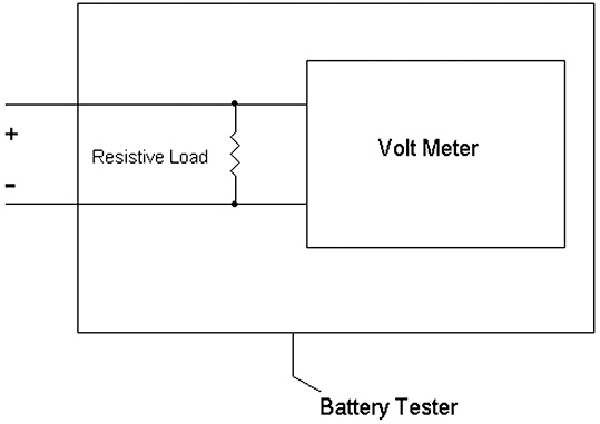
FIGURE 3-33 Block diagram of a (digital) voltmeter used to test batteries via a resistive load.

FIGURE 3-34 Five 15 Ω resistors connected in parallel to a zip-cord wire (left). Three 820 Ω resistors connected in parallel to another zip-cord wire (right).
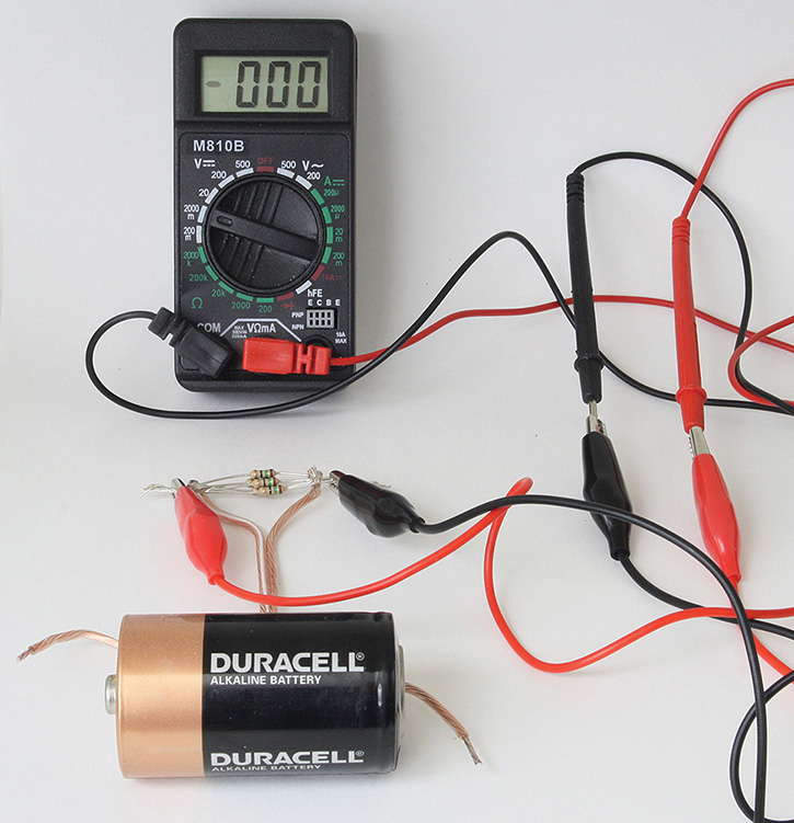
FIGURE 3-35 Example of hooking up the battery to the resistive load and then to the digital VOM.
Parts List
• Any digital VOM
• Two alligator jumper clip leads, preferably red for (+) and black for (–) leads
• Four wires or two short zip cords cut to about 4 inches to 6 inches
• Five 15 Ω, ¼ watt resistors connected in parallel, preferably soldered to one set of wires for testing 1.5 volt batteries
• Three 820 Ω, ¼ watt resistors connected in parallel, again preferably soldered to another set of wires for testing 9 volt batteries
Connect the battery terminals to the wire leads as shown in Figure 3-35. Test the battery for about 3 to 5 seconds to get a steady reading on the digital VOM, and use Table 3-2 to determine the voltage range for a good and bad battery.
NOTE Make sure that the respective resistive load is tested with the correct battery voltage.
References
1. Alfred P. Morgan, Wireless Telegraphy and Telephony. New York: Norman W. Henley Publishing Company, 1922.
2. Eveready Battery Applications and Engineering Data. New York, NY: Union Carbide, 1968 or 1971.
3. RadioShack, Enercell Battery Guidebook. Niles, IL: Master Publishing, 1990.
4. Ronald Quan, Build Your Own Transistor Radios. New York, NY: McGraw-Hill, 2013.