
CHAPTER 4
![]()
Light Emitters and Receivers
We will explore light-emitting devices that turn electric current into light, such as incandescent lamps and light-emitting diodes (LEDs). The relative efficiency of these two types of light-emitting devices will be compared, and some experiments and simple projects will be introduced. Later on, photonic receiving devices that convert light into electricity will be examined. These receiving devices include solar cells and photodiodes. We shall see later that light emitting diodes and small signal germanium or silicon diodes convert light into electric current.
Incandescent Lamps
An incandescent lamp is made with a wire filament enclosed in a bulb without oxygen and glows as the filament is heated. Less than 10 percent of the electrical power into an incandescent light bulb is converted into light, and the rest is converted into heat. Lamps of this type are still used, but they are being replaced with fluorescent lights or light emitting diodes. The incandescent lamp therefore is a resistor that just happens to give out light. But what type of light?
White light is measured by its color temperature in degrees Kelvin (K). Typically, when we look outside on a sunny clear day, the Sun along with the blue sky provides a color temperature of about 4,500 to 5,500 degrees Kelvin. As the sun starts to go down in the afternoon, the color temperature drops to about 3,000 to 4,000 degrees Kelvin. Finally as the sun sets, we can clearly perceive the sunlight with a yellow to red tint, which means the sun’s color temperature has dropped below 3,000 degrees Kelvin. Human eyes adapt to the color temperature for the most part from about 3,000 to 5,000 degrees Kelvin and perceive light in this range as “white,” albeit at 3,000 degrees Kelvin, it has a warm tone. A standard incandescent bulb for room lighting such as a 100 watt bulb provides light at about 2,700 degrees Kelvin, which provides warm white light.
For studio or movie lighting, generally the color temperature is a bit whiter (between 3,200 and 3,500 degrees Kelvin, and sometimes up to 4,000 degrees Kelvin). Halogen lamps or white photoflood lamps provide light in this color temperature range. Incandescent lamps exceeding 4,000 degrees usually are specially made and they are often coated in blue. For standard low-power lamps such as flashlight bulbs or indicator lights, the color temperature is somewhere between 2,000 and 3,000 degrees Kelvin.
One can find out how any of these lamps look color temperature–wise by setting a digital camera’s “White balance” setting to “Sunlight” and taking pictures while a flashlight or other incandescent lamp is on. Then view the picture on your monitor and you will notice a yellow or orange tint. The human eyes and brain adjust to these lower color temperatures and balance what is really a yellow or orange light as a warm white tone.
Incandescent bulbs can be raised in color temperature by using krypton or halogen lamps. Another way of raising the color temperature of an incandescent bulb is to manufacture a lamp to normally operate at a lower voltage, such as 110 volts instead of 120 volts, and then to run the bulb at 120 volts to provide a higher color temperature. The downside is that the life of the bulb is shortened considerably. For example, a 5,000 degree photoflood lamp for photography runs at 120 volts and has a guaranteed life of only 6 hours. The filament in this bulb is run much hotter than a standard 120 volt lamp one would buy for bathroom or living room lighting.
If raising the filament current beyond its standard operating level causes a dramatic shortening of its life, is the opposite true? That is, does lowering the current below its normal level increase its life? The answer is yes—and by a lot. A standard 120 volt AC 100 watt bulb normally lasts about 750 hours, but a 125 volt or 130 volt 100 watt bulb will last thousands of hours at 120 volts.
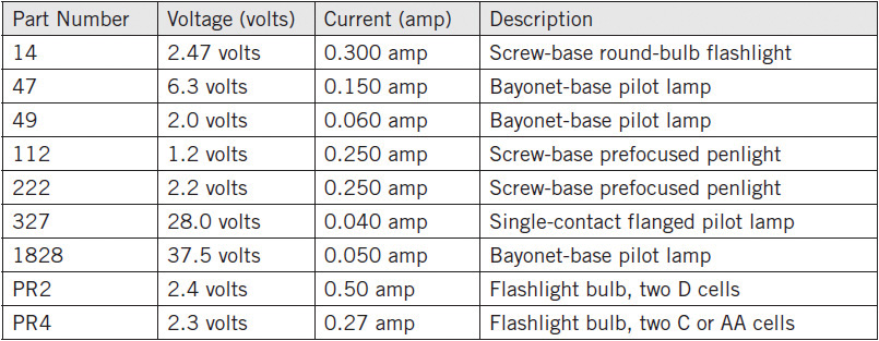
So if you want to extend the life of an incandescent bulb, just lower the voltage by about 5 percent to 10 percent. For example, if you have a typical flashlight bulb such as the PR2, rated at 2.4 volts, run it at about 2.2 volts, which will give a dimmer and more yellowish light, but it will last a lot longer. By the way, most flashlight bulbs are specified for about 10 hours of life, which may seem short, but since we generally use a flashlight intermittently, about a few minutes at a time, its bulb will last for years. Table 4-1 lists incandescent lamps and their standard operating voltages and currents.
TABLE 4-1 Incandescent Lamps for Flashlights and Indicators
An Experiment with a #222 Penlight Bulb
In this experiment, we will look at the relationship between current draw and voltage across the #222 lamp, a bulb that has been used in many penlights using two AA or AAA batteries. We will measure the bulb’s current draw with 1.5 volts and 3.0 volts for the supply. Also, the bulb’s filament resistance is measured with an ohmmeter. After each reading for voltage and current, we shall calculate the resistance of the bulb by using Ohm’s law, that is, R = V/I (see Figures 4-1 and 4-2).
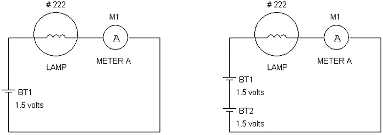
FIGURE 4-1 Schematic diagram of the test circuit with one and two cells providing current to a #222 bulb.

FIGURE 4-2 (a) A three-dimensional (3D) wired prototype test circuit for measuring current draw and voltage with one cell. (b) Current draw measured with two cells.
Parts List
• Double AA cell battery holder with two AA cells
• Two digital volt-ohmmeters (VOMs), but one VOM is workable
• Jumper clip leads
• #222 lamp
• Lamp holder for miniature bulbs
Alternatively one can wrap a wire around the #222 bulb’s outer screw contact and solder a wire to the middle contact to bring out the two connections of the bulb.
To apply two different voltages to the lamp, we use a battery holder for two cells. A digital VOM is set to measure current at 10 amps full scale, and it is placed in series with the battery. Due to the resistances in the digital VOM and the jumper wires, another VOM (not shown in the figure) measures the DC voltage across the lamp. A jumper lead selects power from one or two cells. The results are shown in Table 4-2.
TABLE 4-2 Current Draw of a #222 Light Bulb with Various Voltages Across It and Their Equivalent Resistances
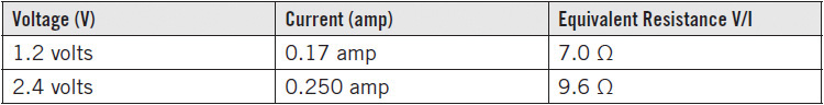
As seen in Table 4-2, the voltage across the 222 lamp provides a current that is somewhat proportional but not linearly proportional. By linearly proportional, we mean that a doubling in voltage across the 222 bulb should result in a doubling of the current. That is, with 1.2 volts and a 0.17-amp current drain, one would expect at 2.4 volts that the current drain would be 2 × 0.17 amp = 0.34 amp. We find instead that doubling the voltage across the lamp actually results in less than twice the current as predicted or expected since the measured current is 0.25 amp. The reason is that the increase in temperature of the filament causes more resistance. To further illustrate this point, with the bulb unlit, the measured resistance (with a digital VOM) is about 1.0 Ω, which is much lower than the equivalent resistances of the partially and fully lit bulb at 7.0 Ω and 9.6 Ω.
What do we take away from this experiment on incandescent bulbs? The resistance is lower when the filament is colder than when filament is hotter. Another important characteristic of incandescent lamps is that they are not polarity sensitive. You can reverse the battery voltage into them, and they will light up the same. Moreover, as we also know, they work fine with AC voltages, which are voltages that alternate in polarity.
Light-Emitting Diodes
Light-emitting diodes (LEDs) are semiconductors that give out light when current is applied in one polarity (forward bias), and no light is given off when in the opposite polarity (reverse bias). Because LEDs are diodes also, electricity only conducts in one direction when the anode of the LED is coupled via a resistor or directly to the positive terminal of a supply and the cathode is connected to the negative terminal.
For example, in the LED keychain light from Chapter 2, the positive terminal of the battery is connected to the anode lead of the LED, while the cathode of the LED is connected to the negative terminal of the battery. However, reversing the LED leads will not allow the LED to be lighted. Figure 4-3 shows how to identify the anodes and cathodes of LEDs, and Figure 4-4 provides a close-up view of a LED. When you buy a LED, the short lead is the cathode, and long lead is the anode.
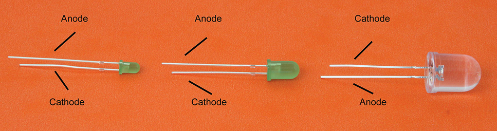
FIGURE 4-3 3 mm, 5 mm, and 10 mm LEDs with lead identifications.
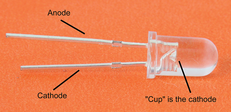
FIGURE 4-4 Close-up view of a LED, where identification of the cathode is via the cup.
Unlike incandescent lamps that generally give out a full light spectrum from infrared to blue light, most LEDs give out light at only portions of the spectrum. These LEDs come with infrared, red, green, blue, yellow, violet, and ultraviolet emitted light. But what is the sequence of colors starting from the longest to the shortest wavelengths?
To answer this question, we go to our “friend,” the resistor color code, which is based on the order of colors seen in a rainbow. Highlighted in bold are the common visible colors available in LEDs. Recall that for resistors, part of the color code includes
• 0 = black
• 1 = brown
• 2 = red
• 3 = orange
• 4 = yellow
• 5 = green
• 6 = blue
• 7 = violet
Starting from the invisible longest wavelength, infrared, the color code tells us correctly that the sequence of visible colors will be red, yellow, green, blue, and violet from the order of the longest to the shortest of wavelengths for visible light.
In solid-state physics, which we do not have to know, there is a bandgap voltage that is related to the turn-on voltage of a LED. The higher the frequency or shorter the wavelength, the higher is the bandgap or turn-on voltage. Normally, a straight voltage source such as a battery or power supply is not connected to the LED unless we know that the applied voltage source is safe enough to do so without damaging the LED. How do we know this? First, we need to know the turn-on and turn-off characteristics of LEDs. The safest way to light up an LED is to include a series resistor. See Figure 4-5.
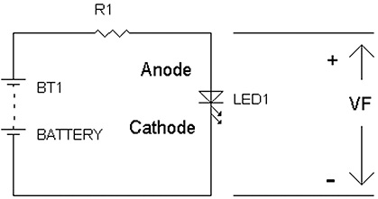
FIGURE 4-5 LED driven via a series resistor R1.
Now let’s take a look at the minimum voltage needed to light up various LEDs. Table 4-3 lists typical turn-on voltages for LEDs, denoted by VF.
TABLE 4-3 Turn-On Voltage VF for Various LEDs
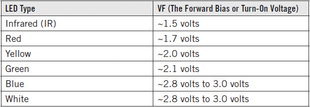
But what about the white LED? It turns out that the white LED is really a blue LED that “cheats” by having the blue light excite a yellow phosphor to provide a white light that mimics a full-color spectrum like incandescent or fluorescent lamps. To see if this is true, see Figure 4-6. Here we will take a lit blue LED on the right and shine it into an unpowered white LED that has the yellow phosphor shown on the left to emit white light.
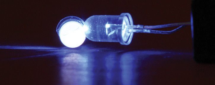
FIGURE 4-6 Shining blue light from the right into an unlighted white LED on the left produces white light.
NOTE Since a white LED is really made from a blue LED, the turn-on voltage for a blue and white LED is the same.
Driving LEDs
Once an LED has a voltage applied beyond the turn-on voltage, the LED current will increase exponentially. Theoretically, about every 0.100 volt added to the turn-on voltage will result in an increase in LED current by tenfold. Depending on the LED, the actual number varies, and it is between 0.060 volt and 0.120 volt of increase for a change in LED current by tenfold.
For example, consider connecting a voltage source such as BT1 in Figure 4-5 directly to a white LED (i.e., there is no series resistor, or R1 = 0, in Figure 4-5) and turning it on initially with 2.60 volts that results in 0.01-mA of LED current. If we increase the LED voltage by 100 millivolts to 2.70 volts, the LED current will increase 10× to 0.10 mA. And if we increase the voltage by another 100 millivolts, resulting in 2.80 volts, the white LED current will increase another tenfold to 1.00 mA.
Put another way, every increase of 200 millivolts results in an increase in a particular LED current by a hundredfold. This is actually true until we take into account of the internal (series) resistance inside the LED. However, the internal resistance values in LEDs vary, and we cannot depend on these internal resistance values to drive a LED reliably. Therefore, to be on the safe side, always add an external series resistor to the LED or have the LED current driven. A current-driving circuit will be shown in Chapter 6. Generally, the external resistor value is larger than the internal resistance of the LED. For example, an external resistor may be 470 Ω, which is greater than the most internal resistances, which are typically less than 50 Ω. To determine the driving current of a LED, consider the following: given a voltage source BT1 that is greater than the LED turn-on voltage VF and series LED resistor R1, the voltage across the resistor is BT1 – VF (see Figure 4-7).
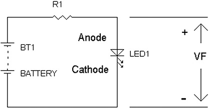
FIGURE 4-7 A voltage source BT1 driving an LED via R1.
Also, we know that the current flowing into the LED resistor goes into the anode of the LED. Therefore, the current flowing through the resistor is the same as the LED current since the LED acts as a termination load to the resistor. Thus, the LED current is
ILED = (BT1 – VF)/R1
For example, given a 5 volt supply for BT1 and a 1,000 Ω resistor for R1, for a typical white LED, the turn-on voltage VF is 2.8 volts, and the resulting LED current is (5.0 – 2.8)volts/1,000 Ω = 2.2 mA. For a yellow LED, where VF is 2.0 volts, the resulting current will be (5.0 – 2.0)volts/1,000 Ω = 3.0 mA.
For indicator lamps, typical LED currents are 1 to 10 mA. In LED flashlights, the current range is 5 to 50 mA for each white LED. Specialized LED bulbs can handle 1 watt or greater. For example, a 2 watt white LED has a turn-on voltage of about 3 volts and requires about 670 mA to deliver 2 watts (i.e., P = VI = 3 × 0.67 ≈ 2 watts).
Light Output Specifications for LEDs
The standard unit for measuring light output from a LED is the millicandela (mcd) for a specified LED current such as 20 mA. Until about 1983, the typical LED light output was about 10 mcd. However, by the mid-1980s, ultrabright LEDs began to emerge. These were brighter red-orange (660-nanometer wavelength) LEDs that were headed for the automobile market. In fact, an LED lamp assembly was to replace the incandescent third tail light in a car. During those days in the mid-1980s, the rated output of ultrabright red LEDs was 500 mcd, then 1,000 mcd, and then up to 2,000 mcd. The light output just kept on increasing as time passed. Also, in the middle to late 1980s, blue LEDs were just beginning to be manufactured, and the price was very high (in the hundreds of dollars for just one).
At the year 2013, one can routinely buy inexpensive white LEDs that provide about 24,000 mcd for 20 mA of current. In a dark room, an LED like this one was found to give off light with 0.8 μA, which is less than 1 μA (microamp). At 10 μA, this white LED was clearly visible in a normally lighted room. With efficiency like that, it is easier to make an LED flashlight with longer battery life, or make an emergency lamp that runs off a hand-squeezed generator. For example, with just 1.5 mA into a 24,000 mcd white LED would provide sufficient light for searching in the dark.
An improved longer-life LED keychain flashlight was featured in Chapter 2 (Figure 2-16), where the two original 2016 batteries were replaced with one 2032 battery. To further improve this flashlight, we can increase the light output by replacing the original LED. Note that the lead of the cathode of the LED has an insulating sleeve to prevent shorting out the (+) and (–) terminals of the battery. Be sure to remove the insulating sleeve from the original white LED and insert it into the cathode of a newer, brighter white LED of 24,000 mcd or more. Figure 4-8 shows where the light output is compared between the newer higher-light-output LED with the original LED. Each LED is driven with a 2032 battery.
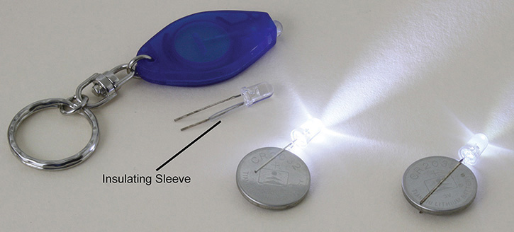
FIGURE 4-8 Comparison of a newer, brighter LED with the dimmer original LED.
LEDs Compared with Incandescent Lamps
For 120-V AC lamps, the compact fluorescent lamp is about 3 to 4 times more efficient than an incandescent lamp for the same amount of wattage. The LED lamp is about twice (2×) as efficient as the compact fluorescent lamp, which means that the LED lamp is about 2 × (3 to 4) or about 6 to 8 times more efficient than the incandescent light bulb.
Note that an LED projects light out from a two-dimensional surface, which is different from a regular bulb that emits light in all directions three-dimensionally. Another difference between an LED and an incandescent lamp (light bulb) is that as the voltage or current is reduced in LED, the tint of the light stays the same, as opposed to the light bulb that has a deeper color (e.g., from yellow to orange or orange to red) when the filament has reduced current. Therefore, the color temperature is essentially constant with an LED independent of current drive. Put another way, dimming an LED maintains the original color with just less light output.
Experiments with LEDs
LED Experiment 1
For providing small amounts of light, such as an indicator light to show that a device is on, typical currents for an incandescent lamp are 60 mA to 150 mA. To show just how efficient LEDs are in terms of converting electricity into light, we will show that an LED can be powered with a 220 μF capacitor driving the white LED at about 0.138 mA or less.
Given that R1 = 47 kΩ, BT1 = 9 volts, and VF ≈ 2.5 volts, the LED current is
ILED1 = (BT1 – VF)/R1 = [6.5 volts/47 kΩ] = 0.138 mA
In Figures 4-9 and 4-10, the 9-volt battery charges capacitor C1 for a second or two, and the white LED will stay on for a while. See Figures 4-9 and 4-10.
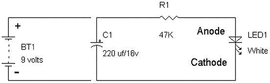
FIGURE 4-9 Schematic diagram of the circuit.

FIGURE 4-10 3D wired prototype of the circuit showing the LED being lighted by only the capacitor.
The circuit consists of a capacitor as a temporary storage “battery” that is charged with a 9-volt battery. The 9-volt battery’s (+) and (–) terminals are connected to the (+) and (–) terminals of the 220 μF, 16 volt electrolytic capacitor for about one or two seconds, and then it is disconnected from the capacitor. The capacitor delivers 9 volts to the 47 kΩ resistor, which provides about 138 uA to the white LED. The LED will stay on for seconds with the 220 μF capacitor, but the reader is encouraged to try a different capacitor, such as a 47 μF, 100 μF, 470 μF, or 1,000 μF capacitor, all being at least 16 volts in rating. Just be mindful that these electrolytic capacitors are polarized and that the battery charging the capacitor must be applied appropriately to the (+) and (–) terminals of the capacitor.
Parts List
• 9 volt battery
• 47 kΩ resistor (¼ watt, 5%)
• White LED (preferably at least 24,000 mcd, but a lower-light-output LED will also work)
LED Experiment 2
Earlier, it was noted for an ideal LED without an internal series resistor, every 100 mV of increase added to the turn-on voltage results in a tenfold increase in LED current. However, all LEDs include an internal series resistor. For many white LEDs after a few hundred microamps of current are applied, more than 100 mV is needed to generate a tenfold increase in LED current. For example, for the C503D-WAN white LED from Cree, Inc., at 2.9 volts, the LED current is 5 mA, and at 3.65 volts, the current increases to 50 mA. Therefore, instead of an increase of 0.10 volt, it took an increase of 0.75 volt from 2.9 volts to yield a tenfold increase in LED current.
NOTE Advanced Math: The equivalent internal series resistance from the Cree white LED example is approximately:
![]()
This is internal series resistance of this Cree white LED. The specification sheet for this Cree white LED states that usable light is provided with 3 volts or less for VF.
The next experiment is designed to determine whether a 24,000-mcd white LED will provide enough light with just two AA cells. The measured current with two NiMh batteries was 1.5 mA at 2.8 volts, and 9.8 mA at 3.2 volts with two alkaline batteries. Although the alkaline batteries provide much brighter light, the NiMh batteries supply 1.5 mA of current for useful lighting in the dark, which will last at least 1,000 hours, or 41 days, continuously. This makes a good emergency light! See Figure 4-11.
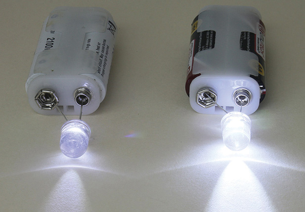
FIGURE 4-11 Two white LED experiments with NiMh cells on the left and alkaline AA cells on the right.
Parts List
• Two NiMh AA cells
• Two alkaline AA cells
• Two 10 mm (or 5 mm) white 24,000 mcd LEDs
• Two double AA battery holders with 9 volt battery connectors or equivalent
For other LEDs, the internal series resistance will vary. For example, see the 9 LED flashlight in Figure 4-12. After measuring the current for the 9 LEDs, it was determined that the 9 LEDs wired in parallel give an equivalent internal resistance of about 3.3 Ω, which then results in each LED having an internal series resistance of 3.3 Ω × 9 = 30 Ω. That is, nine 30 Ω resistors wired in parallel is equal to 30 Ω/9 = 3.3 Ω.
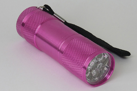
FIGURE 4-12 A nine-LED flashlight.
Photoreceivers
Devices that convert light into electricity can be classified into two categories:
1. Solar cells, which act as a voltage source or battery
2. Photodiodes, which convert light into an electric current
Figure 4-13 shows a rechargeable LED light on the left and on the right, after hacking into the LED light, its 9-cell panel solar cell array. These cells are “wired” in series. Each cell generates about 0.6 volt to develop a total of 9 × 0.6 volt = 5.4 volts to charge the 3-volt rechargeable battery, which then can be used to power the three LEDs (see Figure 4-14). A steering diode D1 provides charge only to the battery BT1 so that the rechargeable battery does not discharge through the solar cells when there is little or no light falling on them.
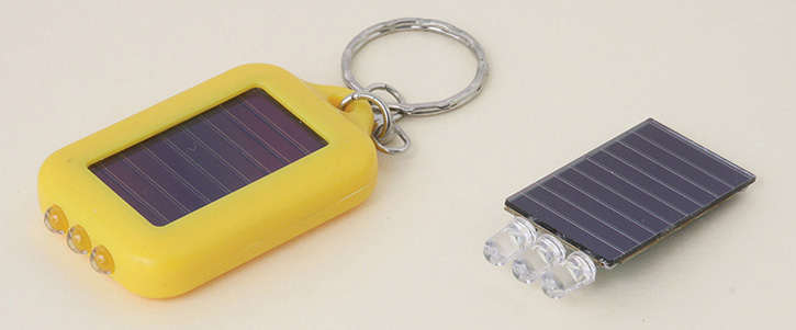
FIGURE 4-13 Solar cell LED light on the left and its solar panel on the right.
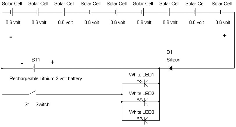
FIGURE 4-14 Schematic of the solar cell LED light.
Note that the LEDs are connected in parallel and that they are connected straight to battery BT1, which this design can “get away” with because the voltage is known to be about 3 volts, and the battery has some internal resistance that prevents overdriving the LEDs. Normally, driving LEDs include series resistors, but in this case, the device works just fine.
A solar cell is essentially a voltage source very much like a battery that is modeled as a voltage source and an internal series resistance VR1. The solar cell’s internal series resistance varies with the amount of light cast onto it. With more light, the lower the value of VR1, the internal series resistance, which allows more current output capability from the solar array. With less light falling on the array, the internal series resistance VR1 increases, which then lowers the output current capability of the solar cell. It should be noted also with less light onto the solar cell, the output voltage will drop and will be less than 0.6 volt. (see Figure 4-15).
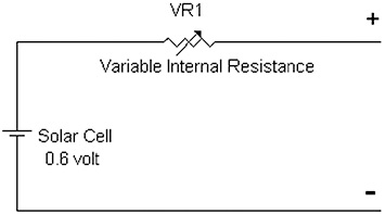
FIGURE 4-15 Schematic representation of a solar cell with a variable internal resistance, VR1, which is dependent on the amount of light received.
The most common photoreceivers today are the photodiode and phototransistor. A photodiode connected to a transistor results in a phototransistor that provides for amplified photocurrent. Figure 4-16 shows a schematic of a photodiode and phototransistor (photo NPN transistor).
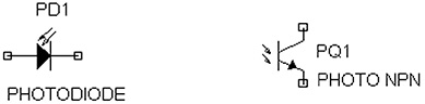
FIGURE 4-16 Photodiode and photo transistor (NPN) schematic diagrams.
A photodiode converts light into electric current and is not considered to be like a voltage source from a solar cell. Thus the photodiode is a light-controlled current source. The more light that falls on it, the more current is generated. Figure 4-17 shows a “real” photodiode, and Figure 4-18 shows where an LED or small-signal diode can be used as a photodiode.

FIGURE 4-17 Photodiode with its anode (longer) and cathode (shorter) leads identified, which are the same for an LED.
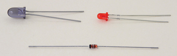
FIGURE 4-18 Two LEDs and a small-signal glass silicon diode used as photodiodes, which produce much less current than a standard photodiode.
NOTE Using LEDs and small-signal or zener diodes as photodiodes results in much less photocurrent when compared to a standard photodiode.
Notice in Figure 4-17 that the photodiode does not have a cup, as seen in a LED (see Figure 4-4), but instead has a flat dark plate. This is one way to immediately distinguish or identify a photodiode from an LED.
So what exactly is a current source? First, let’s look at the concept of an ideal voltage source or something close to it. For example, let’s look at a 1.25 volt NiMh AA cell. If we put the two leads of a 12 Ω, ¼ watt resistor across the (+) and (–) terminals of the AA cell, we will read 1.25 volts across this AA cell, with about 100 mA of current draw via the 12 Ω resistor.
Recall that I = V/R = (1.25 volts/12 Ω) ≈ 100 mA. Now try the same experiment with a 120 Ω and 1,200 Ω resistors for current draws of 10 mA and 1 mA, and you will find that the voltage across the battery is still 1.25 volts. That is, regardless of the current draw from an “ideal” voltage source, the voltage is still the same.
An ideal current source supplies a specified current to a load or resistor regardless of the value of the resistor or load. Also, the output of the current source does not change with voltage across the current source. A photodiode then “dumps” current into a resistor based on the amount of light it receives. For example, if the photodiode generates 1 μA and is connected to a 100 kΩ resistor, 0.1 volt will be generated across the 100 kΩ resistor. That is, by Ohm’s law, 1 μA × 100 kΩ = 0.1 volt. And, if the resistor is changed to 10 kΩ, the photodiode current is still dumping 1 μA into the 10 kΩ resistor to provide 0.010 volt across the 10 kΩ resistor. And again by Ohm’s law, 1 μA × 10 kΩ = 0.01 volt.
Photodiode Experiment
We will look at measuring currents generated from LEDs, photodiodes, and silicon small-signal diodes. A zener diode is a voltage reference diode that can be used as a photodiode and will be covered in Chapter 5. Briefly, as a voltage reference diode, the zener diode works in reverse-bias mode (positive supply via a resistor to the cathode and negative supply to the anode) and provides a reference voltage from about 1.2 volts to over 100 volts depending on the zener diode’s part number. In the forward-bias mode, the zener diode provides about 0.6 volt (positive supply via a resistor to the anode and negative supply to the cathode). The experiment will use whatever LEDs, diodes, or photodiodes the reader has at hand (see Figure 4-19).
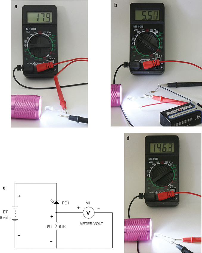
FIGURE 4-19 (a) Flashlight shining into the LED to measure voltage across the two LED leads on the 200-mV scale of the digital VOM. (b) Reverse biasing a photodiode via a 9-volt battery to allow a higher voltage to be read via measuring 5.5 volts across a 51 kΩ resistor, which results in 107.8 uA of photocurrent. (c) Schematic for measuring voltage across the 51 kΩ resistor. (d) Flashlight shining into a photodiode to measure current.
In Figure 4-19a, the measured voltage is 17.9 mV across the LED. The digital VOM “automatically” has a 1 meg ohm (1 MΩ) input resistance. Thus the photocurrent is [17.9 mV/1 MΩ =] 17.9 nA. If a photodiode were used instead, the voltage measured would be much higher because of its greater efficiency to convert light into current when compared to an LED or diode used as a photodiode. If the reader measures a photodiode’s voltage as shown in Figure 4-19a, the maximum voltage would limit out at about 0.4 volt DC because the photocurrent will develop a forward-bias voltage across its own photodiode. To more accurately measure the photocurrent, the photodiode is connected in reverse-bias mode by hooking up the positive terminal of a battery or supply to the cathode of the photodiode. This is shown in Figure 4-19b, and the schematic is shown in Figure 4-19c.
In Figure 4-19c, the photodiode’s current from its anode dumps positive current into R1 to develop a voltage across R1. Via Ohm’s law, this voltage is equal to the resistance value of R1 multiplied by the photodiode current. The reader is then encouraged to try different values for R1. Without moving the LED flashlight and the photodiode, change the resistor value of R1 by using jumper leads to parallel another resistor to R1. For example, take another 51 kΩ and parallel it to R1, and the voltage should drop by half because two 51 kΩ resistors in parallel provide ½ × 51 kΩ. Because the photocurrent does not change, the voltage drops by half because the new resistance value drops by half. Recall that V = IR. A more direct way of measuring photocurrent is simply to connect the photodiode to the digital VOM and measure for current on the 200 μA scale (see Figure 4-19d). In Figure 4-19d, the digital VOM is set to the 200 μA scale, which reads 146 μA of photocurrent generated from the photodiode.
Parts List
• Digital VOM (any)
• A 9-LED flashlight with fresh batteries or any very bright flashlight
• Alligator-clip leads
• LEDs, glass diodes, or photodiodes
• 9 volt battery and its connector
• 51 kΩ resistor(s)
Experiment for Listening to a Remote Control’s Signals
For a second experiment on photodiodes, did you know that you can “listen in” on your remote control? A remote control sends out a series of light pulses whose frequencies are in the audio range. All we need to do is to connect a photodetector such as a 1N914 or 1N4148 signal diode to a simple amplifier that drives a loudspeaker (see Figures 4-20, 4-21a, and 4-21b).
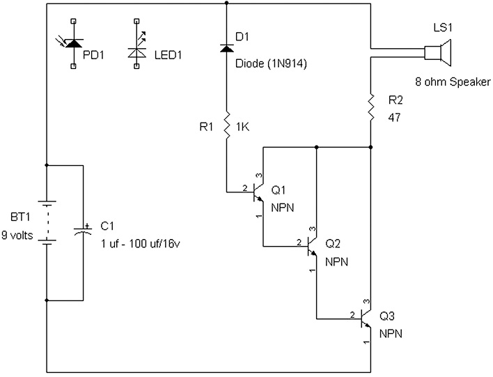
FIGURE 4-20 Schematic including a 1N914 (D1) or IR photodiode (PD1) or IR LED (LED1) connected to a three-transistor loudspeaker amplifier.
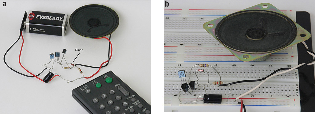
FIGURE 4-21 (a) Prototype board in 3D style of the photodiode loudspeaker amplifier. (b) Photodiode receiver using a superstrip board.
The schematic in Figure 4-20 shows that an LED or photodiode may replace D1. Note that if a LED is used as a photodetector, it is generally only sensitive to the wavelength it emits. For example, a red LED can sense red light but has poor sensitivity to other than red light, such as green, blue, yellow, or infrared light. The remote control provides infrared (IR) light, so you should use an IR LED as the photodetector in this experiment. Other types of LEDs most likely will not produce sufficient photocurrent from the remote control. Note that the remote control’s own LED is placed very near the photodetector (D1, LED1, or PD1) for this experiment.
Parts List
• 9 volt battery
• Three NPN transistors (e.g., 2N3904, 2N4124, 2N2222, or 2N4401) of virtually any silicon type
• 1 kΩ resistor
• 47 Ω resistor
• 1μF to 100 μF, 16 volt electrolytic capacitor
• Loudspeaker (4 Ω to 100 Ω)
• IR LED or photodiode (e.g., RadioShack Part 276-0142)
• Silicon glass diode (e.g., 1N914, 1N4148, or glass zener diode > 10 volts)
• Any remote control with a LED emitter
The photodiode D1 is a common small-signal silicon diode. D1 is connected in reversed-bias mode with the cathode being tied to +9 volts. The anode is connected to a 1 kΩ series resistor R1 that acts to protect diode D1 and transistor Q1 should D1 be connected incorrectly. The other lead of the 1 kΩ resistor is connected to the base of Q1, which amplifies the photocurrent from D1. The emitter output of Q1 is connected to the base of Q2 to further amplify the photodiode’s current. Finally, the emitter output of Q2 is connected to the base of Q3 to yet amplify the photodiode’s current again. The collector output of Q3 then supplies sufficient pulsating current to the loudspeaker via the 47 Ω series protection resistor (see Figures 4-20 and 4-21a).
To allow a change to various other types of photoreceivers, such as LEDs, germanium diodes, photodiodes, zener diodes, etc., one can build the amplifier on a super-strip and simply replace each photoreceiver/diode on the board (see Figure 4-21b). Just be aware of the polarity of the diodes. That is, the cathode is tied to the +9 volt supply. If the LED used as a photodiode lights up, the leads need to be reversed. Also note that a 9 volt supply may provide too much reverse bias to an LED used as photodiode, and therefore, the supply voltage may be reduced from 9 volts to 4.5 volts.
We have seen in this chapter that LEDs give out light and can be used as photosensors as well. LEDs also have turn-on voltages for specific colors or wavelengths that can be used as voltage reference diodes. In Chapter 5, we will look into other types of diodes that are used for rectification and voltage references. Chapter 6 will cover transistors and show you that LEDs are also useful as voltage references for transistor circuits.
References
1. “Cree 5 mm C503D-WAN LED Data Sheet,” Cree, Inc., Durham, NC.
2. “Osram SFH 229 Photodiode Data Sheet,” Osram GmbH, Munich, Germany.
3. Hewlett-Packard, Optoelectronics Fiber-Optics Application Manual, 2nd ed. New York: McGraw-Hill, 1981.
4. Infrared Emitter and Detector, Part 276-0142 (includes a data sheet for the IR detector and emitter), RadioShack, Fort Worth, TX.
5. Assorted LEDs, Part 276–1622 (includes data sheets for the red, green, and yellow LEDs), RadioShack, Fort Worth, TX.