
Introduction to CSP systems and performance
P. Heller German Aerospace Center (DLR), Cologne, Germany
Abstract
This chapter introduces into the principles of concentrated solar power (CSP) technologies, its main components as well as typical plant concepts. It covers the main technologies, i.e., solar tower, parabolic trough, linear Fresnel, and dish/engine systems and discusses the importance of performance assessment for each, always under the aspect of the market demand for such assessment. This introduction also provides the historical background from the first commercial plants until the market size of 5 GW in 2016. Also, the development of research and test infrastructure and key R&D projects are presented, highlighting their role in developing methods, tools, or infrastructure for performance assessment. A general overview on the CSP markets and the expectation for the future growths of the sector is given. Finally, the main important research laboratories are presented which provide knowledge and services for performance assessment of the technology.
Keywords
Concentrated solar power; Trough; Tower; Linear Fresnel; Dish; History; Applications; Solar plants; Laboratories; Meteorological stations; Markets
1.1 General introduction to CSP
Concentrated solar power (CSP) systems are characterized by focusing solar radiation with the help of reflectors onto a receiver, where the radiation is absorbed and transferred to heat. A heat transfer fluid (HTF) carries the heat from the receiver to a heat engine, i.e., a steam or gas turbine, connected to an electrical power generator (see Fig. 1.1). Instead of producing electricity, the heated HTF can also be used to drive a thermochemical process to produce, e.g., hydrogen, syngas, or even fertilizer.


Using CSP technology for electricity production is the most mature application, counting in 2016 with a market size of approx. 5 GW installed power [2]. Therefore, this book focuses only on concentrated solar energy for electricity production. Since the key for further deployment of the technology is the performance of commercial systems, this book has the goal to present all important information about the methods, instruments, and infrastructures to assess the performance of commercial CSP components and plants. Fig. 1.1 shows the four major CSP technologies: parabolic trough, linear Fresnel, tower, and dish systems.
1.1.1 History of CSP
The history of CSP technology goes back to ancient Greece and China, where mirrors or glass were already used to make fire. In the early 20th century, when simple machines had already been invented, the first plant based on parabolic trough technology for pumping water was established in Meadi, Egypt by the American Frank Shuman [3].
At the end of the 1970s, after the oil crises in 1973 and 1979/80, the first research projects were started to replace fossil fuels for electricity generation by solar energy. These focused on research and development of the technology in order to demonstrate the technical feasibility. In Europe, an activity of the International Energy Agency IEA led to the development of a parabolic trough and a solar tower demonstration facility in Almeria, Spain, planned and built by several countries: Germany, Spain, Italy, Belgium, Greece, Sweden, Switzerland, and the United States. The project was named a Small Solar Power System (SSPS), and was later integrated with new installations to the Plataforma Solar de Almería (PSA), today Europe's largest test site for CSP. The working group of IEA was later named SolarPACES [4].
At the same time, several commercial projects started, such as CESA-1 in Spain and THEMIS in France [4]. These were mainly based on evaporating and superheating steam to drive steam turbines in the power level of 1–2 MW. Since shortly after commissioning of these plants, the oil price went down again and the expectations for competitive commercial applications of CSP did not become reality, they were operated commercially for only a few years. They were then shut down or handed over to research institutes with the objective to work on the technology's cost reduction to become cost competitive in the future.
In 1981, the United States planned to have the first power tower plant with steam turbine technology, i.e., Solar-1, 10 MW, operated in Barstow, California. A little later, the first larger deployment of CSP became reality. In 1984, the SEGS-1 plant (Solar Electric Generation Station) was built in the Mojave desert in California. It consists of parabolic trough technology heating a thermal oil and superheating steam to produce electricity with a steam turbine with a generator. In the following years, several new plants were built leading to an installed capacity of 354 MW (i.e., SEGS-II to SEGS-IX). For many years, even after the bankruptcy of the developing company LUZ Power Generation in 1991 [17], these plants were the only commercial installations of CSP. Their nominal power was successively increased from plant to plant, i.e., from 14 MW in SEGS-1 to 80 MW in SEGS-IX (Fig. 1.2).

With the help of the Global Environmental Facility of the World Bank, three commercial integrated solar combined cycle (ISCCS) power plants were built in Egypt (Kuraymat), Morocco (Ain Benimatar), and Algeria (Hassi R'Mel) [18].
In 2004 [19,20], Spain introduced a feed-in tariff for CSP, and by this was initiating the construction of approximately 1.3 GW of capacity, built in the years 2007–14 (18). Motivated by the good experience in California and Spain, and by the desire to reduce fossil fuel consumption in order to lower CO2 emissions, many countries started to implement commercial CSP projects.
1.1.2 First CSP test infrastructures
Initiated by the oil crisis of the 1970s and in parallel to the enthusiastic planning of the first commercial CSP power plant projects, several large-scale research installations for CSP were initiated [4]. Among them were the following:
• Central Receiver Test Facility (CRTF), today named National Solar Thermal Test Facility (NSTTF), at Sandia National Laboratories, United States;
• Central Receiver Research Facility at Weizmann Institute of Science (WIS, 1988), Israel;
• Solar Furnace at CNRS, France;
• Test Field Station TFS IVTAN, Russia;
• High Flux Solar Furnace PSI, Switzerland;
• High Flux Solar Furnace NREL, United States;
• High Flux Solar Furnace at Parkent, Uzbekistan; and
• Small Solar Power System (SSPS), Almeria, Spain.
As a consequence of the oil price decrease in the early 1980s, all commercial projects except the SEGS Plants were either shut down or were modified to serve as platforms for R&D projects and merged with the above-mentioned new infrastructure for component testing.
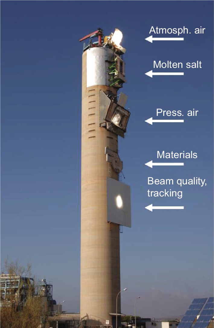
A good example for this transition is the CESA-1 tower facility (see Fig. 1.3). Initially built and operated as superheated steam system generating electricity of 1 MW, it was then turned into a versatile test platform with the aim to decrease cost of the critical components. In the subsequent two decades, numerous tests of different technological solutions were conducted in research projects, such as:
• GAST [21];
• ASTERIX [21];
• TSA [21];
• SOLAIR [22];
• REFOS [23]; and
• SOLGATE [24].
The CESA-1 tower facility also served for tests of new heliostats, control systems, flux measurement systems, and other measurement devices or tools. The same occurred to most of the other infrastructures.
All these research projects were driven by the question: which technological approach would be best suited for commercial projects and which had the highest potential for cost reduction and high performance? Regarding tower technology, the options receiving major investigation were superheated steam, atmospheric air, pressurized air (for gas turbines), and molten salt. Many new designs for heliostats were tested. In parabolic troughs, the same HTF (synthetic oil) as in the SEGS Plants was used, but new collector designs and later on the Direct Steam Generation (DSG) technology were tested. The linear Fresnel technology was first deployed in the late 1990s, and most developers started with the direct steam generation technology to demonstrate higher cycle temperatures than the existing synthetic oil technology as HTF. The material research focused on developing high temperature insulation materials, absorbers, or catalyst for solar-chemical applications such as hydrogen production.
1.2 Design and components of CSP technologies
The four major CSP technologies—solar tower, parabolic trough (PT), linear Fresnel (LF) and dish/engine (i.e., dish/Stirling or dish/gas turbine)—are different in their focusing principles and generally in their design. However, there are common characteristics for the involved major subcomponents of a CSP power plant. Mirrors are aligned to concentrate the light onto a receiver. They are therefore curved to reach an appropriate concentration factor depending on the required operation temperature to run the thermodynamic cycle. The mirrors are tracked to follow the path of the sun during a day; therefore they are connected to a support structure which is actuated by a one- or two-axis drive system. A control system takes care of the proper alignment of the collectors during the day. The receiver absorbs the solar radiation and transfers the heat to a fluid. This hot fluid may directly drive a heat engine, transfer the heat to a secondary cycle (e.g., steam generation), or allow storing the energy for later use during hours without sunshine (Fig. 1.4).

CSP plants may be divided into four major blocks: solar field (including HTF and receiver system), storage, power block, and balance of plant. Fig. 1.5 shows a cost breakdown for a 100 MW parabolic trough and solar tower plant. It can be seen that additional cost elements such as owner cost, engineering, and site preparation or contingencies represent approximately 20%–25% of the total cost.

Compared to fossil fuel power plants, CSP technologies require a high investment at the beginning, while the “fuel cost,” i.e., solar radiation, is free throughout the lifetime of the plant. Therefore it is of the highest importance to reach a low component cost and thus minimize the initial investment. Thus, financing of a project also has a great impact on the economics.
To reach competiveness, all involved components need to be as efficient as possible, and simultaneously of high durability and low cost. Generally, the performance of a CSP plant depends on:
– high reflectance and geometrical precision of mirrors;
– precise tracking of concentrators;
– high absorptance, low emittance of receivers;
– efficient transfer of the heat to the turbine;
– high efficient thermodynamic cycle (for power production);
– efficient storage of heat;
– high durability of all components; and
– low maintenance efforts.
Fig 1.6 gives an overview of typical performance losses in a parabolic trough collector system.

The performance assessment of CSP components presented in this book focuses on the solar field. The power block is assessed with the same tools as in a conventional power plant. The plant control is proprietary for each plant developer and not accessible for externals for its qualification. Storage systems also have a very specific, proprietary design. The performance of heat exchangers is monitored using data of the system control unit and is therefore not followed here.
In the solar field, the major components to be assessed are the collectors consisting of foundations, mirror support structure, reflectors/mirrors, absorbers/receivers, drives, and control system. In parabolic troughs, flexible joints such as ball joints or flexhoses are also important components. Linear Fresnel systems and even some tower concepts use a secondary concentrator mirror close to the absorber tube to increase the flux and/or the optical efficiency. The HTF should be chemically stable and/or maintained in a way that it will not harm the receivers; this is important in a synthetic oil system when too much hydrogen gas content may influence the performance of the vacuum receivers.
Table 1.1 gives an overview on the components of a solar field and the respective assessment parameters.
Table 1.1
Components of the solar field and assessment parameters
| Component | Assessment parameter |
| Reflectors/mirrors | Reflectance, shape |
| Receivers | Absorptance, emittance |
| Collector support structure | Stiffness, mirror attachments |
| Drives/tracking | Tracking precision, wear |
| HTF | Chemical stability, hydrogen content, corrosiveness |
| Flexible Joints | Reactive forces, tightness |
| Valves, pumps | Functionality |
| Foundations | Alignment precision |
For all these components, the durability is a prerequisite necessity. Typically a lifetime of at least 20 years is required for all components of the solar field.
1.2.1 Reflectors/mirrors
The mirror is the key element to achieve the desired high temperature in the different CSP technologies. Depending on the technology, the mirrors are shaped differently and may need to have different compositions.
(a) Tower systems
In tower applications, mirrors are required to reflect the sunlight from the heliostat field onto the receiver. A heliostat holds the mirrors (also named reflectors) and tracks them according to the path of the sun. The mirror is attached to a back structure, mostly of a metal framework. The heliostat is typically of a size between 2 and 180 m2 [25]. Since the mirror size is limited by the manufacturing and handling process, larger mirror areas have to be composed from individual mirror facets. These have to be aligned to create overlapping images when directed to the receiver. This alignment process is called “canting”. Additionally, each facet must be curved according to the distance between heliostat and receiver to reach high concentrations. Although it would be ideal to apply an individual focal length for each facet, in most plant configurations (especially for larger plants), the focal lengths are grouped to minimize canting cost. All heliostats of the group use the same focal length.
Fig. 1.7 shows different heliostat designs.
Even if the canting may be done precisely for one orientation of the heliostat, it might be the case that the focus is not performing well at other orientations during the course of the day and year. Fig. 1.8 shows a beam spread at a different hour of the day after the successful canting of the heliostat. Two individual foci may be distinguished on the target. Both foci represent the image of both wings of the heliostat. In this heliostat, the torque tube was designed too weak and the lowered stiffness is leading to flexions of the two wings of the heliostat under different gravity loads.
Due to scattering in the atmosphere, heliostats in close proximity to the receiver produce a smaller focal spot and reach higher flux densities than heliostats at greater distances. This effect is used to distribute the solar radiation from the different heliostat ranges to reach a homogeneous flux pattern at the receiver by filling areas of the receiver with less flux with the help of heliostats from closer ranges. This is necessary since the image of each facet is a Gaussian distribution, and in most cases the receiver is of rectangular shape.
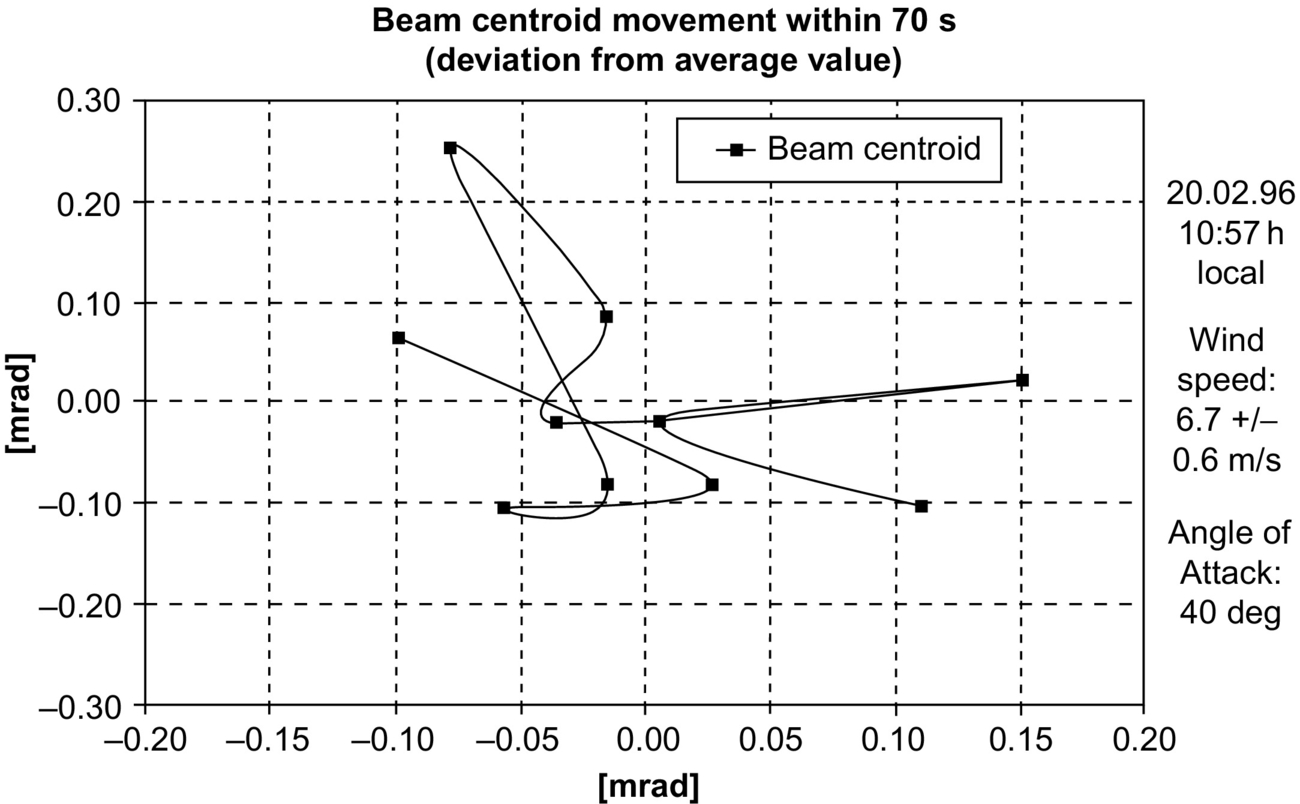
Another important aspect is the precise tracking of the heliostat. It is important to know the characteristics of the tracking to avoid flux peaks on the receiver. Often, even if the aim point of a heliostat is fixed during the course of the day, the real flux peak might be at a slightly different location than the aim point due to gear wear, gravity effects on the support structure, or the control of the motors. Due to optical errors, of which astigmatism has the biggest influence, the image of a facet also changes throughout the day at the receiver plane. Fig. 1.9 shows the beam centroid movement of the ASM-150 heliostat during the course of the day. It can be seen that the focal spot moves significantly during a windy day with wind speeds of 6.7 m/s. It becomes obvious that it is important to assess the deviations of the focal spot positions and correct it as much as possible, to allow for a proper and stable flux distribution across the receiver.


(b) Parabolic trough systems
In parabolic trough systems, mirrors are aligned along the axis of the trough. The typical configuration in parabolic troughs such as the LUZ [26] or the EUROTROUGH design [27] is that the parabola is produced by only two differently shaped mirror facets, i.e., one for the inner and one for the outer parabola. As such, four mirror facets compose the whole parabola due to symmetry (see Fig. 1.10). The facets concentrate the radiation in a focal line where the tubular receiver is placed. Tracking is only necessary in one axis.
For the performance assessment of mirrors in a parabolic trough system, reflectance and shape precision are the main parameters of concern. Since they are attached to a support structure, there is often an influence observed introducing additional loads onto the mirror panels. It is important not only to analyze mirrors in an ideal frame in the laboratory, but also to analyze such effects in the solar field after attaching mirrors to their support structure. These additional loads may vary according to different orientations of a collector or misalignment of the support structure, and should be taken into account (see Fig. 1.11).


(c) Linear Fresnel systems
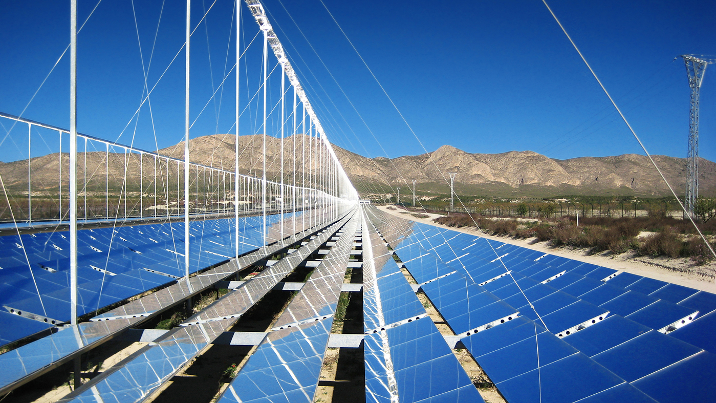
Depending on the general design of linear Fresnel systems, the mirrors might be plane or are only slightly curved. Plane mirrors suffer from too high optical losses, therefore mirrors are usually one-axially curved by gluing them on a slightly curved support structure. The principles are the same as in parabolic troughs, but mostly the support structures are made of continuing areas of curved sheets, while mirrors are made of thin glass (Novatec) (see Fig. 1.12). Performance analysis therefore must often be made directly in the field instead of in the laboratory.
(d) Dish/engine systems
Mirrors of dish/engine systems underlie in general the same requirements as, e.g., heliostat or trough mirrors. High reflectance and accurate shape are demanded. There are different designs for dish concentrators. The largest dish is the 400 m2 BIG DISH, developed at ANU, which was even considered to be increased to 500 m2 by Wizard Power Pty Ltd. [28]. The mirror facets were made of silvered glass attached to a metal framework. Each facet had to be aligned to direct the radiation towards the receiver. Another concept is the EURODISH design, where thin glass mirrors are glued onto a sandwich facet. Here, the shape is provided by the facet of glass fiber reinforced plastics. All facets are glued together to form a uniform shell [29]. Shape assessment is therefore done with field measurement systems. Fig. 1.13 shows the slope error assessment with the help of a colored target placed in the focus of the concentrator and observed from a distance (ideally at infinite).
Since dish/engine systems have not yet been commercially deployed, the assessment of the performance of such system is currently limited to prototype testing by research institutions or industry [42].

(e) Beam down systems
In tower systems, it may be of interest to place the heat conversion unit on the ground. Therefore, a beam down mirror concept had been developed. A secondary mirror is placed above the heliostat field and redirects the radiation from the heliostats onto a receiver on the ground. The focal length of each heliostat must consider the additional path lengths of the rays until reaching the receiver. Beam down systems have not yet been commercially introduced.
(f) Secondary concentrator technology
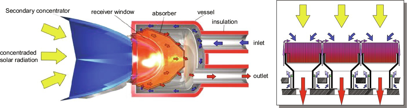
In tower systems, secondary concentrators allow an increase in the flux level onto a receiver by a mirror setup directly in front of the receiver. The radiation level at the outer areas of the Gaussian focal flux distribution is lower than in the center. The secondary concentrator redirects the radiation from these outer low flux areas towards the exit area of the secondary concentrator. As a result, not only may the average flux level at the outlet be increased, but also the flux distribution is more homogeneous.
The performance assessment of secondary concentrators is done by measuring the reflector reflectance and by measuring input and output power at the secondary concentrator (Fig. 1.14).
In Linear Fresnel systems, a secondary reflector is often placed at the backside of the receiver tube to reflect radiation that is missing the receiver towards the backside of the receiver tube (see Fig. 1.18). Such, the flux distribution, i.e., the thermal load, is better distributed around the tube and smaller tube diameters are applicable. The assessment of the performance is done by field measurements and/or simulations for the whole receiver assembly.
1.2.2 Receiver
The receiver absorbs the radiation and transfers the absorbed energy to a HTF. A high absorptance of solar radiation and a low emittance of thermal radiation are the most important parameters to reach high conversion efficiencies from radiation to heat. Depending on the application, the receiver looks very different.
(a) Towers
The receivers of superheated steam and molten salt systems are made of steel tubes. In such applications which require high temperatures, the receiver surface is either uncoated and or painted with a black paint. When uncoated, the oxidation of high temperature steels or alloys at air leads to a relative quick-developing oxidation layer. This has advantageous properties, since the oxidation layer is a thin and passive layer of high absorptance. In many applications, this is considered to be sufficiently high to accept to avoid any further treatment of the surface to increase absorptance more than that. The absorptance of tower receivers is reported to be close to 90% [30]. The emission of heat from the hot surface is depending on the emittance of oxidized ferritic or austenitic steels, and can be found in literature. In some applications, a ceramic paint was applied to increase absorptance further. Unfortunately, these paints are not sufficiently resistant to their environment and may only help to increase efficiency up to 95% in the first time of operation [31]. Below this paint layer, the steel develops the same oxidation layer as on unpainted steels. Therefore painting is often used to avoid the uncontrolled oxidation/blackening of the receiver during the first days of operation. Local changes in optical properties would lead to overheating at areas where the absorption increases first due to oxidation. Since the system control is based on medium outlet temperatures of the receiver, the mass flow through the receiver tubes would be reduced to reach the design temperatures and by this provoking local over temperatures with the risk of material damage.
In addition to reflectance and emission losses, the high temperature receivers also suffer from convection losses due to their exposition to winds at the elevated altitudes. Examples of these receivers are the molten salt Solar-2 and the Ivanpah design (see Fig. 1.15).
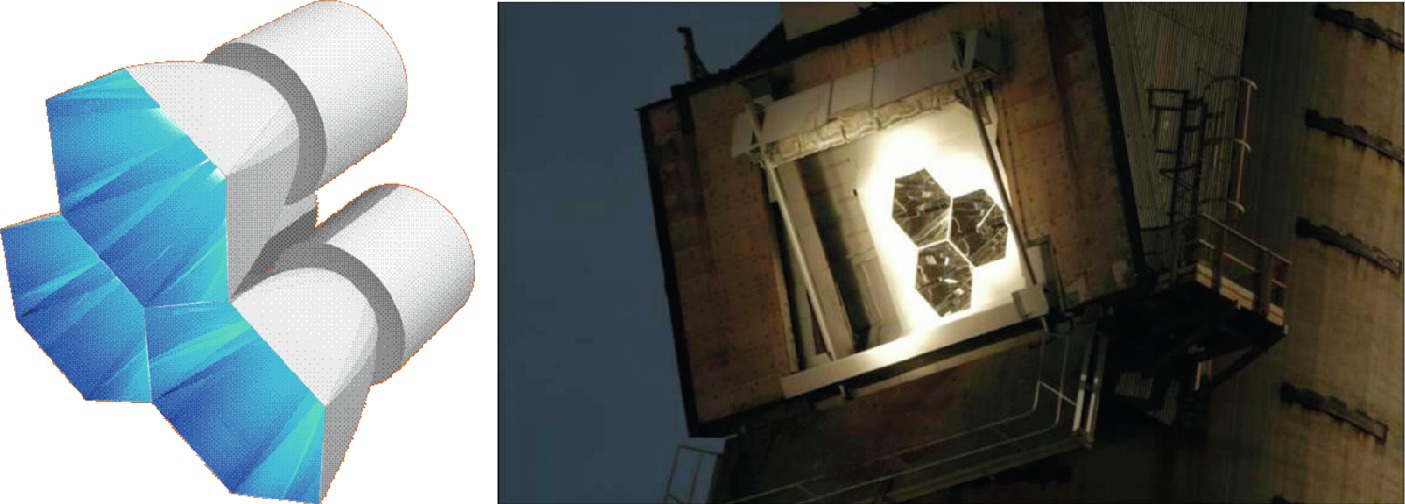
Receivers for air systems are not yet commercial; they currently exist only on a demonstration scale. For temperature application below 800°C, they may use metal high temperature steels such as INCONEL 750 or HAYNES. Other applications, such as Brayton cycles, demand ceramic absorbers and closed receivers. Such receivers are much more complex (see Fig. 1.16, left). An open volumetric receiver prototype for superheated steam generation, as shown in Fig. 1.16 (right), is made of ceramic absorbers in a steel shell.

(b) Parabolic troughs
In parabolic troughs, the temperatures are much lower, i.e., < 400°C.
A glass envelope tube of borosilicate glass allows the application of a continuous vacuum between glass and receiver tube, which helps to isolate the absorber surface towards the environment. The glass surface is very resistant to abrasion and has a high transmittance, so the performance is much higher than in unprotected absorber tubes. Fig. 1.17 shows the design of such receivers.
The absorber tube is coated with a selective coating to increase absorptance and decrease heat losses. The heat loss increases exponentially with the absorber temperature (see Chapter 4, Fig. 4.7).


(c) Linear Fresnel
The receivers of linear Fresnel systems are either the same as the ones for parabolic troughs (i.e., a glass envelope and evacuated metal absorber tubes) or they are embedded in a secondary concentrator assembly. Such a configuration is shown in Fig. 1.18.
The receivers allow a higher concentration ratio and a better distribution of the flux around the absorber tube. Since these receivers are not evacuated, the upper part of the secondary mirror is equipped with an isolated cover. The secondary mirror has an elliptical geometry. Often a glass cover is used to close the space between outer shell and the entrance of radiation below the absorber tube for higher receiver performance due to lower convection losses.
1.2.3 Collector and support structures
The mirrors are attached to the support structure. In most collectors this consists of a steel framework, which is oriented towards the sun by the actuators or drives. The mirror attachment points of the framework must be very precise, because any geometrical error may influence the orientation of even the shape of the mirrors. Fig. 1.19 shows the support structure of a heliostat (left) and a parabolic trough collector (right).

The points of attachments must be measured after assembly of the structure and, if necessary, adjusted further. The measurement preferably should be done in the manufacturing hall, or in the field for prototypes. A photogrammetric measurement is illustrated in Fig. 1.20, which gives valuable information about failures during manufacturing or assembly.

Other designs of support structures are using torque tubes with stamped lever arms (Sener) or fiber glass sandwiches connected to a torque tube (Solarlite).
1.2.4 Heat transfer fluid
Although a broad variety of HTFs are used in prototype systems, only a few are used in commercial systems. A major role is played by synthetic high temperature oil, which is used in most parabolic trough plants. The other HTF is molten salt, which has recently been used more frequently in tower systems, while superheated steam systems are losing attractiveness. This is mainly due to simplification and avoided costs for the heat exchangers between receiver and storage in molten salt systems.
The temperature limit of oil as an HTF is below 400°C. Since operators desire the upper cycle temperature to be as high as possible, the plants are operated as close as possible to this limit. However, this requires a proper maintenance of the oil circuit, since at high temperatures the oil gets chemically unstable and decomposes faster. The resulting gas phases have to be separated from the liquid to avoid a reduction of the heat transfer coefficient from the absorbers into the fluid due to a too high gas content. On the other hand, one of the most problematic gases produced is hydrogen, which may penetrate through the absorber tubes into the vacuum and increases the heat losses of the receivers to the ambient. Hydrogen as all other gases evaporized in the HTF loop is separated in a special tank. The amount which diffuses into the vacuum of the receiver is absorbed in the getter material placed in the vacuum.
The properties of oil as an HTF should be monitored throughout the lifetime of the plant. By decomposition, the heat capacity may be reduced. Samples may be drawn from commercial plants and analyzed in the laboratory. A first measurement system for online monitoring of the heat capacity was developed in [33].
In a molten salt systems, corrosion of the tubes, especially at the receivers, has to be monitored. The thermophysical properties of salts are relatively stable over the lifetime as long as no corrosion products are introduced due to erosion from corroded surfaces.
Superheated steam was used in an Abengoa plant PS20 [34] and in Ivanpah [35]. Both developers are meanwhile working with molten salt as an HTF in future commercial tower plants.
1.2.5 Flexible receiver connectors
In parabolic trough plants, ball joints [8] or flexible hoses [9] are the linking element between the fix drive section and the movable concentrator. These are designed so as not to introduce additional forces on the structure, and must be leak-tight to avoid possible environmental risks. They must absorb large amounts of single and multiple plane displacements, including rotation. Fig. 1.21 shows both types of assemblies.

In linear Fresnel plants, the receiver tubes are not rotating. However, the longitudinal expansion of the pipe is much higher, since the receiver tube covers the whole loop length with one single tube. As such, the flexible connector must compensate for the expansion in just one axis, but over a longer distance compared to parabolic troughs. Fig. 1.22 illustrates this.

The assessment of the performance of flexible connectors focuses mainly on durability aspects. The daily temperature gradients and movements stress the flexible element and may lead to rupture or leakages. Manufacturers as well as research institutes are examining the durability of flexible connectors in special test benches. Fig. 1.23 shows a test bench at a manufacturer [9]. Assessment of flexible connectors in manufacturer-independent tests is described further in Chapter 7.

1.2.6 Meteorological station
Concentrated solar power plants require Direct Normal Irradiance (DNI) in order to generate electricity. Since the level of irradiance is almost proportional to the generated electricity of a plant, it is of high interest to determine the DNI with the highest possible accuracy. This information is decisive already during the project development with the aim of qualifying a certain site of implementation and predicting the conditions for commercial suitability.
Until today the site specific available solar resource is only available with a sufficiently high accuracy if a locally installed meteorological station with appropriate instrumentation is used. The measured data must be combined with longer historical data sets from satellite and numerical weather prediction models (NWP) to obtain all the required input for the project development with a sufficient accuracy. Beside the general accuracy of the instruments, also the frequency and quality of maintenance and data control is relevant. Also the temporal resolution of the data must be sufficiently high to allow simulations including the transients in the solar field which influence the detailed design of the plant.
However, the meteorological data are not just important during the project development. The guaranteed plant performance has to be demonstrated during the acceptance testing phase. The result of this measurement campaign is decisive for any additionally required technical improvement actions to reach the contracted efficiency or for any compensation payments. For this testing phase only the ground based meteorological measurements achieve the required accuracy.
During the operation of the plant, the meteorological measurements are used to analyze the performance of the plant, i.e., to discover any malfunctioning or degradation or loss of performance due to unfavorable operation schemes. Furthermore, forecasted meteorological data are generated and used to optimize the operation and the plant yield.
The meteorological station consists of a number of instruments. The most important measurement for CSP is the DNI. The typically used instruments are either sun-tracking pyrheliometers or a much simpler instrument called a rotating shadow band irradiometer (RSI). The stations also use pyranometers with shading ball assembly to derive the two other relevant radiation components: Global Horizontal Irradiance (GHI), and Diffuse Horizontal Irradiance (DHI).
Other additional sensors provide information about:
• relative humidity;
• barometric pressure;
• wind speed, gust, and direction;
• precipitation;
• beam attenuation between the heliostat and the receiver;
• circumsolar radiation; and
• soiling, etc.
For the forecasting of DNI in the next 15 minutes so-called all sky imagers are required. Forecasts with a longer forecast horizon are obtained from satellite data and NWP models. The required amount of maintenance of meteo stations depends a lot on the instruments used. For example, pyrheliometers demand daily cleaning of the entrance window. In remote areas, the power supply of meteo stations is usually realized by photovoltaic (PV) panels with solar batteries. If grid connected, a UPS is necessary. The data are transferred either via cell phone modems to the service company or directly connected to the plant operator. A fence is usually needed to protect the instruments from distraction or manipulation. A typical setup is shown in Fig. 1.24. More detailed information can be found at Refs. [10,11].

1.3 Main applications and markets
1.3.1 Solar-only plants
The first commercial CSP power plants were designed as solar-only plants without storage. The main reason for this was the priority in the successful demonstration of the young technology in the markets. In particular, the financial institutions had to be convinced about the maturity, the cost, and the reliability of the technology. The solar-only concept without storage was also economically favorable under certain funding schemes, such as those in Spain. The steam generated by the heat of the solar field was driving the turbine/generator set, and directly producing electricity. In cloudy conditions, the power output decreased, and overnight no power was delivered at all. Only a small amount of fossil co-firing was allowed to overcome short cloud periods or to preheat the system in the morning. This amount was limited in Spain to a 15% share of fossil-generated energy [20].
With the decreasing cost of PV, it became obvious that CSP could not compete in the markets without its main advantage, i.e., providing power on demand using thermal storage. Today, the majority of new plants are designed with sufficient storage capacities to deliver power during evening and night time, and thus filling the gaps that PV and wind energy may not be able to cover. Storage also has a positive effect on the levelized cost of electricity (LCOE) due to an increased capacity factor which makes the technology more competitive.
Most of the new installed commercial power plants use the concept of heat either a synthetic oil or molten salt with the solar field and store part of the energy delivered from the field in a molten salt storage. When using synthetic oil as an HTF part of the energy delivered by the solar field is used to generate steam for the turbine throughout the sunny hours, while the other part is stored after a heat exchange in a molten salt tank allowing power generation during clouds or nights (see Fig. 1.4). In tower systems molten salt may directly be used as HTF eliminating the need for the additional heat exchange. The hot salt is directly stored in the tank system. A good example is the Gemasolar solar thermal plant in Spain (see Fig. 1.25) [12].

1.3.2 Hybrid plants
1.3.2.1 ISCCS
ISCCS power plants are composed of a CSP plant and a natural gas-fired combined cycle plant. This technology promises a reduction of fossil fuel consumption and the cost of integrating solar power into the electricity system. It is especially suited for countries with abundant resources of natural gas, such as Algeria, or such countries with a lack of fossil resources which therefore need to reduce their fossil fuel imports, such as Morocco. It was also seen as a technology that could help to cope with the fast increase of electricity consumption in developing countries by a quick implementation of a highly efficient conversion technology [13]. The Global Environmental Facility Trust Fund encouraged Algeria, Morocco, and Egypt to build such plants. More recently, another project started construction in Duba, Saudi Arabia (see Table 1.2). From the small number of commercial projects, it may be deduced that most countries that have opted for CSP projects in recent years have prioritized solar-only plants.
Table 1.2
ISCCS projects [14]
| Start Operation | Project | Country | Total capacity (MW) | Solar capacity (MW) |
| 2010 | Ain Beni Mathar | Morocco | 472 | 20 |
| 2011 | Kureimat | Egypt | 140 | 20 |
| 2011 | Hassi R'mel | Algeria | 170 | 20 |
| 2017 | Duba 1 | Saudi Arabia | 605 | 43 |

1.3.2.2 Fuel saver
Another option to implement solar energy into existing fossil power plants is the combination of coal-fired power stations with a solar field. This concept acts as a fuel saver. In particular, the combination with the Fresnel technology is favorable. In this case, the solar collectors are producing steam which is fed into the preheater or boiler of the coal-fired power station. A good example is the Kogan Creek Solar Boost project in Chinchilla, Australia [14].
The combination of a solar field with a gas turbine system has not yet been commercially implemented. Pressurized solar receivers would increase the temperature of the compressed air from the compressor towards up to 1000°C and feed it in line with the fossil combustion chamber into the turbine stage. Although first demonstration projects showed the suitability in principle, the markets are not yet taking up this technological option. The main reason for this is that the solar share is not considered sufficiently high, since modern turbines operate at much higher turbine inlet temperatures. Another aspect is that until now there is no promising storage option for hot pressurized air produced in the receiver to allow to operate the system with a high solar share.
1.3.3 Markets
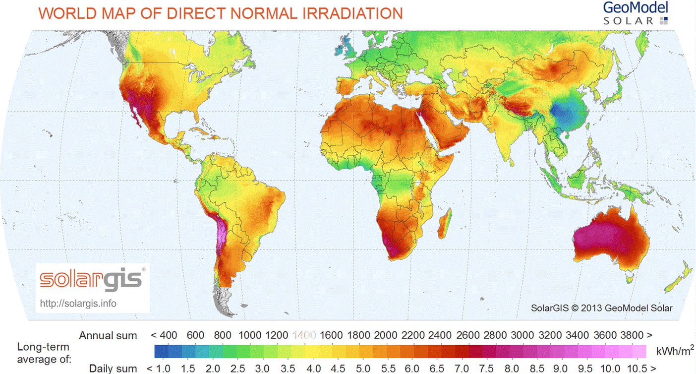
The markets for the CSP technology are generally spoken in the sunbelt of the earth, since only direct radiation (DNI) can be used by the technology. Fig. 1.26 shows the worldwide distribution of the DNI. Although at the beginning of its deployment, the technology had been implemented also in less favorable sites concerning optimum radiation levels, the main markets are considered to be in areas with DNI levels above 2000 kW/m2/year [16]. As the radiation level has a major impact on the Levelized Cost Of Electricity (LCOE) of the plant, countries with extremely high radiation levels such as South Africa or Chile came into focus during recent project developments [16].
The first commercial projects were overwhelmingly based on parabolic trough technology. This was due to the fact that the SEGS power plants had been successfully operating for almost 15 years and banks were favoring this technology assumed it to be sufficiently mature to bear a reasonable financial risk. As such, around 95% of the Spanish plants were using this technology. First plants operated solar only and were limited to 50 MW due to the favorable reimbursement within the given feed-in tariff [20]. Later, storage systems were introduced to increase the power output at the same power block size. A significant milestone was the 20 MW Gemasolar plant in Spain with a 15 hours molten salt storage allowing operation around the clock [12]. Although in the United States, the first projects also relied on PT technology, the move to the promising tower technology for a further cost reduction and an increase of plant size was quickly realized. Solana [36], Ivanpah [35], and Crescent Dunes [37] are good examples of the introduction of large plants in the United States. In other countries, such as Morocco, the first calls for tenders were defining the type of technology, but later projects were then released technology open.
The Fresnel technology fall somehow back in the deployment. After a first larger demonstration project Puerto Errado 1 in the size 1.4 MW a commercial project was placed in Spain in the size of 30 MW, i.e., Puerto Errado 2 [38]. Dish/Stirling systems suffered from the competition of PV, since first demonstrators were solar-only systems, and as such they were not capable of providing an added value compared to PV which achieved drastically fallen costs. Hybrid systems or systems with storage are not yet commercial.
The market size worldwide at the end of 2015 was 4.9 GW, with another 300 MW under construction [16]. These plants under construction are in South Africa, Chile, India, Morocco, and the Middle East. Another upcoming market is in China, where 1.3 GW are under development at the end of 2016 [39]. Fig. 1.27 gives an overview on the installed capacity by technology type.

The market size in the near and further future is predicted by ESTELA assuming three different scenarios: a reference, a moderate and an aggressive scenario. Under these scenarios, the cumulative capacity and the cost is provided in Fig. 1.28. The cost numbers are based on an increasing capacity factor, i.e., an increasing implementation of storage capacity in the future.

1.3.3.1 Drivers for cost reduction
Ref. [16] gives also an overview on the main drivers for the cost reduction of the technology (see Fig. 1.29).

The highest impact on cost reduction will have the development of the technology towards higher process temperature, higher cycle efficiency, scalability, and standardized design. Adaptions of turbines for the operation with daily start-up, improved control, and O&M procedures, as well as lowering the parasitic losses are other aspects to be followed.
In the solar field, the main requirements are to improve optics to reach:
– higher tracking and mirror slope accuracy;
– higher reflectivity of mirrors;
– improved cleanliness of mirrors by antisoiling coatings;
– selective absorber coatings; and
– improved durability.
In addition, design aspects of concentrators play a major role which may help to optimize the amount of involved materials per delivered solar energy from the field. As such, the newer plants involve concentrators with larger aperture sizes, smaller relative absorber tube sizes (lower relative heat loss), and a higher degree of automation during manufacturing and assembly.
The need for the improvement of the cost situation of the solar field has led to many new developments driven by researchers and industry to come up with improved materials and components. Due to the tough financing constraints in the CSP sector, the testing and qualification of all new developed materials or components is a prerequisite for their introduction into the market. This has initiated the creation of suited test methods, qualification laboratories and field performance assessment tools by several research institutions.
1.4 Major test laboratories (infrastructure) for CSP component testing
After the implementation of the first experimental large-scale CSP installations in the 1980s and the implementation of the commercial power plants SEGS in the United States at the beginning of the 1990s, the number of installations to measure the performance of CSP components was limited to those institutions running large-scale test facilities.
These were basically:
– Sandia National Laboratories, United States;
– National Renewable Energy Laboratory (NREL), United States;
– Centro de Investigaciones Energéticas, Medioambientales y Technológicas (CIEMAT), Spain;
– Deutsches Zentrum für Luft- und Raumfahrt e.V. (DLR), Germany and Spain;
– Centre Nationale de la Recherche Scientifique (CNRS), France;
– Paul Scherrer Institut (PSI), Switzerland;
– Weizman Institute of Science (WIS), Israel; and
– ENEA, Italy.
Many of those institutions had built tower facilities in the early 1980s to test prototype heliostats, receivers, or complete CSP subsystems. The main goal was to demonstrate the feasibility of technical solutions and verify high subsystem performance to reduce the cost of CSP to be able to enter the electricity market (Fig. 1.30).

After the market take-off of the CSP technology in 2004 in Spain, several other institutions started either to implement additional test equipment or to expand their knowledge from other technology fields towards CSP. This led to a variety of options for component testing and qualification.
By the end of 2016 more than a dozen research institutes world-wide provide test infrastructure to assess the quality of CSP components or systems. Even more institutions are active in the field of measurement of meteorological data.