
Aircraft Structural Layout
Abstract
An introduction to the structural layout of conventional GA aircraft is provided. Special mentioning of aircraft loads is made to help the student understand how different parts of the aircraft structure are designed to react a specific type of load. Then, information on the characteristics and properties of typical materials used for the construction of the modern GA aircraft. This includes aluminum, steel, titanium, and composite materials. The last section of the chapter presents a description of the fabrication of and installation of various structural components for aircraft, such as the fuselage, wing, and stabilizing surfaces.
Keywords
Steel; aluminum; titanium; composites; graphite; fiberglass; epoxy; carbon; rivets; fasteners; sandwich construction; spar; ribs; hoop frame; longeron; skin; bulkhead; wing attachment; monocoque
Outline
5.1.1 The Content of this Chapter
5.2 Aircraft Fabrication and Materials
5.2.1 Various Fabrication Methods
Structural Analysis of Composite Materials
Pros and Cons of Composite Materials
Aircraft Construction Methodologies
5.3 Airframe Structural Layout
5.3.1 Important Structural Concepts
Monocoque and Semi-monocoque Structure
Steel Truss Covered with Fabric
Composite Sandwich Construction
5.3.2 Fundamental Layout of the Wing Structure
5.3.3 Fundamental Layout of the Horizontal and Vertical Tail Structures
Fabrication and Installation of Control Surfaces
Unconventional Tails: T-tail, V-tail, and H-tail
5.3.4 Fundamental Layout of the Fuselage Structure
Fuselage Structural Assembly – Conventional Aluminum Construction
Fuselage Structural Assembly – Composite Construction
5.1 Introduction
It should not come as a surprise that the layout of the airframe is one of the most important elements of the entire aircraft development process. The structural layout dictates whether empty weight targets will be met and, thus, whether other design requirements can be achieved. Interestingly, a poorly laid out structure may cause problems that, in a worst-case scenario, can potentially lead to the termination of an otherwise viable aircraft development program. For instance, poorly conceived load paths in a pressurized fuselage may result in detrimental structural deformation that can make it impossible to maintain an advertised pressure differential. How such a flaw would affect the development program would ultimately depend on how far along it had progressed when discovered. The required fix could be a major redesign of the fuselage structure and, depending on the program status, its financial stability could be compromised. On the other hand, even the ideal airframe layout will not guarantee the development program becomes a success. An aircraft can be structurally optimized while simultaneously suffering from aerodynamic, power, or systems inadequacies that, ultimately, may bring about its demise. The important point is that while the structural layout cannot make, it can certainly break the viability of the program.
In this section, we will look at some general layouts of aircraft structures, albeit without too much structural analysis, as the focus of this book is primarily conceptual and preliminary design and not detail design. The purpose of the section is to help the designer visualize the implications of the various configuration choices on the resulting structure.
Note that the material properties presented are in the UK system. Use the following factors to convert to the SI-system.
To convert psi to GPa (giga-pascal), multiply by 145037.73773
To convert psi to MPa (mega-pascal), multiply by 145.03773773
To convert lbf/in3 to specific density, multiply by 27.7334934
5.1.2 Notes on Aircraft Loads
Aircraft are designed to react several types of loads as discussed below:
(1) Aerodynamic loads (or airloads for short) refer to forces and moments caused by the dynamic pressure to which the aircraft is subjected. Airloads include forces, such as wing lift and drag, and moments, like wing torsion and bending. Their magnitude depends on the weight of the aircraft, the load factor, its geometry, and, again, dynamic pressure. The total magnitude is defined based on requirements set forth by the aviation authorities – for instance, 14 CFR Part 23 and 25. However, the local values depend on the geometry. Thus, consider two aircraft, A and B, of equal weight and wing area that differ only by the wing aspect ratio (AR) and taper ratio (TR). Assume aircraft A has the higher AR and lower TR. For reasons that will be detailed in Chapter 9, The anatomy of the wing, it will generate substantially higher bending moment than aircraft B.
(2) Inertia loads refer to forces and moments caused by subjecting aircraft components to acceleration. An example is the battery, which does not experience any aerodynamic loads. Its support structure must be capable of reacting the forces that result from the applied load factors. Other components, such as a piston engine, are simultaneously subjected to both aerodynamic and inertia loads.
(3) Operational loads refer to loads other than aerodynamics and inertia that are simply caused by the fact that the airplane is being used. Examples of such loads include door hinge and locking loads, floor loading loads, wing step-on loads and other similar loads. Such loads are often tricky to define, but are usually small compared to, say, the wing loads. Operational loads usually lead to wear and tear.
In addition to the primary role of the airframe, the location and shape of all the major load paths has a major influence on weight. From a certain point of view, it is the responsibility of the structural engineer to design the structure so it will only carry the loads it is likely to encounter in operation. This is imperative to the success of the design. An airplane whose strength is greater than the operational loads is in fact overdesigned; it is stronger and heavier than it needs to be. As a consequence, during each flight, it will carry around a lot of material whose weight would better be a part of the useful load. Additionally, the wings, stabilizing surfaces, engines, and landing gear have major effects on the weight and location of its center of gravity. This can bring about loading problems that may have to be solved using heavy ballast, again, whose weight would better be a part of the useful load.
5.2 Aircraft Fabrication and Materials
The selection of structural material for a new aircraft can be an involved process that requires a number of very important considerations. If an airplane is mostly to be constructed from a single source of material, its selection will clearly have a profound impact on a couple of important areas: manufacturing and maintenance. Established companies tend to stick with the material and fabrication processes they know best from past projects; they are unlikely to change a manufacturing process that may have taken decades and a substantial amount of investment to develop. For this reason, manufacturers of aluminum aircraft are unlikely to invest in the development of a composite aircraft, and vice versa. This does not preclude the introduction of a new material to an airplane, although this will happen on a smallscale at first. Then, if the material is promising, the manufacturer might increase its use in a process of evolution. This approach has been very evident among manufacturers of jet commercial aircraft, such as Boeing and Airbus. The introduction of new materials should not be done unless its characteristics have been carefully evaluated. The following listing provides some areas the designer should understand before new material is selected:
At the time of writing, the most common material used for aircraft remains aluminum. However, the use of composites has gained great popularity and is even seeing extensive use in the fabrication of new commercial aircraft, such as the Boeing 787. Already, several all-composite aircraft, such as the Cirrus SR20 and SR22; Cessna Corvalis (formerly Columbia); and Diamond DA40 Katana and DA42 Twinstar, are certified under 14 CFR Part 23. Aluminum has a number of very important properties that lend themselves well to the construction of vehicles that must be light and yet stiff. Composites are a somewhat recent introduction to the aircraft industry, although their history and use dates back to the early 1950s.
Arguably the best source for material properties data for aerospace vehicles is a document structural engineers know as the MIL-HDBK-5. It contains design information on the strength properties of metallic materials and elements for aerospace vehicle structures. The data in the document are published based on a collaboration effort of the US armed forces, the Federal Aviation Administration (FAA), and the industry, and until recently, were maintained as a joint effort of the FAA and the Department of Defense [1]. MIL-HDBK-5 has now been superseded by the Metallic Materials Properties Development and Standardization (or the MMPDS). The MMPDS is the FAA’s effort to maintain the MIL-HDBK-5 handbook, which is recognized world-wide as the most reliable source available for statistically based allowables in the design of aircraft, as well as for repairs, alterations and modifications.
When using MIL-HDBK-5, one must be aware of the limitations of the statistical methods used to present material properties. The reader must be mindful that the production of aircraft requires uniformity and repeatability. The aircraft produced today must be equally strong as the airplane produced last month, within some statistical limits. This can only be accomplished by uniformity and repeatability in the manufacturing process of material. Each batch of material transported to the aircraft manufacturer is either tested by the manufacturer himself or has a certificate of testing from a third-party test lab that demonstrates its strength is no lower than some specific value. The handbook refers to this as data basis1 and cites four types of room-temperature mechanical properties. These are listed below based on the least to the highest statistical confidence.
• Typical Basis – a typical average value of the material property (e.g. yield stress in tension) and has no statistical assurance associated with it.
• S-Basis – means that the value of the material property is based on industry specifications or federal or military standards. As an example, industry specifications can be those of the SAE or ASTM.
• B-Basis – means that at least 90% of the test coupons are expected to equal or exceed a statistically calculated mechanical property value with a statistical confidence of 95%. For instance, consider the ultimate tensile strength of 2024-T3 sheet, which for a specific sheet thickness might be 64,000 psi. If we test the ultimate strength of 10 coupons of this material, at least nine must equal or exceed 64,000 psi, with 95% confidence.
• A-Basis – means that at least 99% of the test coupons are expected to equal or exceed a statistically calculated mechanical property value with a statistical confidence of 95%.
Typically, structural analysis uses A-Basis allowables for structural members whose failure is considered catastrophic. B-Basis allowables are used for redundant structural members whose failure would result in the redistribution of loads without compromising safety of flight. The reader is directed toward MIL-HDBK-5 for more details.
5.2.1 Various Fabrication Methods
There are a number of manufacturing techniques the aircraft designer must keep in mind during the design stage. Cognizance of manufacturing difficulties that are not always obvious when a particular feature or geometry is suggested, is particularly important. The following are common manufacturing methodologies. Note that introducing these in detail is beyond the scope of this introductory text and the aspiring engineer should acquire as much knowledge of general assembly and construction methods as possible.
Casting
Casting is one of the oldest manufacturing methods known to man, dating back to at least 4000 BCE [2, Table 1, p. 6]. The process entails the following steps:
(1) A mold is created from an already existing part, for instance, by making an imprint of the part in granular material such as sand.
(2) The material for the part is heated until it becomes liquefied at which time it is poured into the mold. An example of this is molten aluminum.
(3) The part is then allowed to cool (“freeze”) for a specific time, during which it solidifies.
(4) Once sufficiently cool, the part is removed from the mold, which is typically destroyed in the process. This gives rise to the saying ‘one part, one mold,’ making the casting process very labor-intensive.
The advantage is that the original model of the part can be shaped from material less strong than the material used in the casting. For instance, it is possible to make the original part from wood, whereas the copies are made from some metal. There are a number of different casting methods in existence that depend on the material used or the desired shape. For this reason, casting takes considerable expertise to do well. Casting of aircraft metals (aluminum or steel) will leave the material fully annealed and thus lacking strength. For this reason casting should never be used for critical aircraft structure.
Molding
The difference between casting and molding is that molding involves the construction of a heat-tolerant mold that is used to make multiple part copies, whereas casting involves one mold per part. Molding has become a very sophisticated manufacturing process that requires considerable expertise. An example of such processes is injection molding, in which material in a liquid form is injected under high pressure into the mold – an operation intended to eliminate air bubbles from the material, which are a source of stress concentrations in the material that can render it far less durable than otherwise.
Sheet Metal Forming
The concept forming refers to the process of forcing the material into a particular shape. Industry has developed a large number of methods to force metals into particular shapes. Presenting all of them is beyond the scope of this book, however, when it comes to aircraft, sheet metal forming and forging are the best known. Forging is presented separately as it is considered by many to be in a class on its own.
Sheet metal is most often formed to introduce flanges to stiffen the material so it can be used for stringers and spars or for joining with other sheet metal parts (see paragraph about joining below). It is sometimes formed to provide the skin curvatures of lifting surfaces, although this is only required when the skin thickness becomes too large for the panel to flex freely. Thicknesses of that magnitude are common in the inboard wing skin panels of commercial jetliners or military aircraft. The thickness of aluminum sheets used for GA aircraft is usually small enough to allow it to flex with ease. The material is usually cut to shape using hand- or hydraulically actuated shears, depending on sheet thickness and cut length. Then, the forming takes place using a special tool called a sheet metal brake. The bending operation requires some planning, as there are limits to how tight the bend radius can be. As a consequence, allowances have to be made for extra material for the bend itself. Another phenomenon, springback, must be considered when working with sheet metals. It requires the operator to bend the sheet to a predetermined angle which is slightly greater than the desired angle. Once removed from the metal brake, the sheet will spring back to the desired angle.
There are two kinds of surface flexing the engineer must be aware of: simple and compound (see Figure 5-1). All metals will readily undergo a simple surface flex (or deformation), which in effect is a simple plate bending. Compound flex, on the other hand, is accompanied by internal twist (shearing) of the material molecules, in addition to bending deformation about two axes. Metals resist this type of deformation so it is practically impossible to form the compound flex unless its internal molecular structure is stretched using specialized forming methods such as hydraulic pressing. This fact is imperative when selecting material for aircraft components. The compound surface is where composite materials shine – but the manufacturing of composites is usually more expensive than for aluminum. If it is imperative that the surface features a compound flex, as is the case for very low-drag aircraft such as sailplanes, consider composites. If it suffices to use a simple surface flex, such as frustum fuselages and simply tapered wings, consider sheet metal.

Extrusions
An extrusion is the process of forcing an ingot of near-molten metal through a die with a specific geometric pattern. This is a common process for aluminum alloys intended for use in airframes, although it is also used to produce structural steel for buildings. The process converts the half-molten ingot into a long and straight column of structural material featuring a constant cross-sectional shape. When made from aluminum alloys it is ideal for use as longerons or stringers in airframes. It is common to find extrusions whose cross-section resembles letters such as ‘H,’ ‘L,’ ‘T,’ ‘U’ (also called ‘C’) and ‘Z,’ and far more complicated shapes are available. Of these, the L-extrusion, usually called an angle extrusion, is of great use as a stringer or a spar cap in aluminum spars. The C-extrusion, usually called a C-channel, is of great use for various brackets and hinges designed to react high structural loads. The use of extrusions in aircraft is extensive and includes not only stringers, but seat-tracks, brackets, wing attachment fittings, and countless other applications. Extrusions have higher material strengths than plates as the formation of it compresses the grain structure.
Forging
The best-known and probably the oldest forming operation is forging, dating back perhaps as far as 8000 BCE [2, p. 384]. Forging is when a metal is locally subjected to large compressive forces in the form of “hammering” using various dies and tools. This hammering can be done to either cold or hot parts, but it usually increases the strength, toughness, and durability of the material through the process of work hardening. For this reason, it is not unusual to see aircraft components that must react large forces, such as landing gear struts, made from forged metals [2, p. 384]. Work hardening is a consequence of the deformation of the grain structure of the material. Since most forged parts are subjected to secondary machining operations to improve appearance, the work hardening tends to complicate the manufacturing process by making it harder to finish. Forging metals such as iron and steel at elevated temperatures will reduce work hardening and make them easier to post-process. With respect to the economics of forging, the designer must choose carefully, as the cost of forging a non-critical part may be much higher than, say, molding.
Machining
Machining is the fabrication of a part through the removal of excess material. There are a number of ways machining takes place, the most common being sawing, cutting, turning, and milling. Like the other methods above, machining takes a lot of expertise and experience to do well, but an understanding of what can or cannot be machined can open the door of success and close the door of failure. Machining aluminum and low-carbon steels (e.g. AISI 1025) is relatively easy, but this becomes gradually more difficult when the carbon content increases. Hardened steels are very difficult to machine and require sophisticated tools to accomplish this. Machining is much easier to accomplish when the material is in its annealed state. Afterwards, it is necessary to heat-treat the part to acquire adequate strength, even though many parts will undergo further machining post heat-treating.
Welding
Welding is the joining of parts made from identical metals by heating them to a point of surface melting and then bringing them together to allow their molecules to coalesce. A filler material is often used to create a stronger joint. Welding is one of the most common ways to join parts and forms a very strong and durable bond between the parts. This contrasts joining of parts using soldering or brazing, both of which do not melt the working parts. A large number of methods can be used to perform the welding: most notable are a gas flame, an electric arc, a laser, and an electron beam. Low-carbon-grade steels are easily welded or brazed by all techniques and the filler material should be comparable in strength to the base metals. Steels with higher carbon levels will often require stress-relieving after the welding has been completed and sometimes even subsequent heat treating. Welding is commonly used to join parts making up engine mounts, landing gear, and fuselages, demonstrating the method can take a beating if properly done. It is a drawback that the process often leads to warping that may change the intended geometry. The welding of critical structural aircraft parts should always be done by a certified welder. Critical structural parts should not be made from welded aluminum due to a reduction in fatigue life.
Joining
Joining is typically used to assemble a large part from many smaller ones. It includes operations such as riveting, using threaded fasteners, welding, and so on. For instance, consider the fabrication of an engine mount, which requires a number of typically tubular parts to be joined through the process of welding (see above). Also, the fabrication of an aluminum wing is accomplished through the joining of ribs, spars, stringers, and skin through the process of riveting sheet metal. The aspiring aircraft designer should acquire a deep understanding of the two most common riveting techniques used in the industry: bucking and blind riveting.
Of the two, bucking is the primary method used and is employed when two (or more) aluminum sheets are to be joined (or to join a sheet to an extrusion) and there is ample access to both sides of the parts to be joined, for the technician. The standard procedure is shown in Figure 5-2 in four steps. First the sheets are aligned using carefully placed clamps (not shown). Then, holes are drilled at specific intervals depending on the shear stress to be transferred from one sheet to the next through the rivets. Since the drilling operation typically forms sharp edges (or burrs) on the opposite side, these must be removed prior to the insertion of the rivets. Otherwise, the joining will not develop full strength.
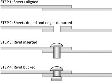
The technician usually and temporarily inserts a special tool through selected holes called a Cleco®. This prevents the sheets from slipping during further drilling or bucking operations. The third step involves inserting the proper rivets into the hole, and the fourth is the actual bucking operation. It often requires two technicians to accomplish, in particular if large sheets are being joined. The technician on the head side of the rivet places an air hammer against the rivet, while the other places a heavy metal block called a bucking-bar against the opposite side of the rivet. When both are ready, the operator of the air hammer presses a trigger on the air hammer to generate a short burst of hammering to the rivet. The inertia of the bucking bar will then deform the rivet such that a solid and strong attachment is formed, as the hammering will cold work the rivet. Bucking takes practice and careless handling of the tools may damage the sheets around the rivet.
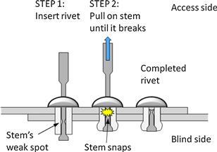
Blind-riveting is only used when lack of access to the back side of the sheets prevents the use of an air hammer and bucking bar. It is also used for non-critical structural assembly. Driving a blind rivet is a very simple two-step operation (see Figure 5-3) in which a special tool, a rivet gun, is used to pull out the stem (or spindle) until it snaps at its weak spot, where its diameter has been deliberately reduced. This allows the stem to be pulled up just enough to compress the opposite end of the rivet and lock it in place. Blind rivets are also available as structural rivets and, as stated earlier, are sometimes the only choice. Cherrymax® is the best known brand for such rivets. Blind riveting, while far easier to perform than bucking, still requires care in installation in order to avoid tilting of the stem, which might misalign the rivet. It is also considerably more expensive that conventional bucking rivet installation.
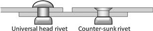
Finally, there are a number of different types of rivet heads, but as presenting all of them is not appropriate in this text, only the two most common types will be cited. These are: universal and counter-sunk rivet heads (Figure 5-4). The universal head (as shown in Figure 5-2 and Figure 5-3) is typically used for low-performance aircraft (in terms of airspeed), whereas the counter-sunk rivet head will be flush with respect to the surface of the sheet. This reduces the drag of the airplane and is thus implemented on high-speed aircraft. However, this brings additional complication to the table that increases the cost of the riveting: counter-sunk rivets require an indentation to be made for the rivet head, either by a special drilling operation or forming of a dimple using a special tool. Either one increases production costs.
Next to rivets, threaded fasteners (or bolts) are the most commonly used fasteners in aircraft (see Figure 5-5). Such fasteners have superior tensile (and shear) strengths compared to rivets (which are only intended for use in shear), but are far more expensive to use. Like all aircraft hardware, threaded fasteners must be traceable to an approved manufacturing process. Most bolts used for aircraft applications are general-purpose (e.g. AN-3 through AN-20 bolts), internal-wrenching (e.g. MS-20004 through MS-20024), and close tolerance (e.g. the hex-headed AN-173 through AN-186 or NAS-80 through NAS-86).
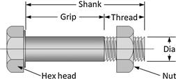
The shank of these bolts features a smooth section, called the grip, and a threaded section onto which the nut is mounted. The length of the grip must be equal to or slightly exceed the thickness of the material it is intended to hold. The nut must be tightened or torqued to the right amount to preload the fastener. This ensures the joined parts do not slip during service, ensures a more uniform transfer of loads, and increases the fatigue life of the fastener. Nuts are usually self-locking or non-self-locking. Castellated nuts are a type of the latter that are locked in place using special safety-pins called cotter-pins. Such nuts are required for all structurally critical parts, such as engine mounts, landing gear, and wing attachments. The installation of threaded fasteners should always use flat washers (e.g. AN960) so that torquing the nut will not damage the surface of the joining materials.
5.2.2 Aluminum Alloys
Aluminum is a lightweight and corrosion-resistant structural material that can be strengthened further by chemical and mechanical means. Chemically, the strength is increased by adding specific elements to it (see Table 5-1). It is this process that turns the aluminum into an alloy. Mechanically, the strength is increased via cold working and heat treatment. The primary advantages of aluminum alloys are low density, high strength-to-weight ratio, good corrosion resistance (Alclad), ease of fabrication, diversity of form, electrical conductivity, isotropy, abundance, and generally repeatable properties.

One of the most important properties of aluminum is that it is mostly isotropic. Isotropic materials offer strength and stiffness regardless of the orientation of the force being applied. Aluminum sheets used for aircraft construction are mostly isotropic as there is a slight difference between the “rolled” and “transverse” directions. Aluminum sheets are produced by first casting molten aluminum into a thick sheet, which is then hot rolled (at 500 °F to 650 °F) until a specific thickness is achieved. Then the hot-rolled sheet is annealed and cold rolled until a desired “retail-ready” thickness is produced. This process gives the sheet bi-directional properties, although the structure featuring it is analyzed is if it were isotropic. Repairing aluminum is much easier than most other materials used for aircraft construction. This is another very important property as it makes field repairs practical. Aluminum has been the primary material for aircraft construction since before World War II, although the use of composites has begun to threaten its stature.
At this time, aluminum accounts for about 75–80% of commercial and military aircraft. According to data from the General Aviation Manufacturers Association (GAMA) from 2005,2 some 65–70% of GA aircraft were made from aluminum. Of the number of different aluminum alloys available, generally three types are used more than others: 2024, 6061, and 7075. Table 5-1 lists the major alloying element for the different types of aluminum. Wrought alloys are rolled from an ingot or extruded into specific shapes. The word “wrought” is the archaic past tense of the verb “to work.” “Wrought alloy” literally means “worked alloy.” Cast alloys are melted and poured in a liquid form into molds where they are allowed to cool. These two methods lead to two very different classes of alloys, in which wrought alloys are stronger as a consequence of special post-processes such as cold working, heat treatment and precipitation hardening.
Ultimately, the properties of aluminum alloys are determined by the alloy content and method of fabrication. Besides strength, the designer must be aware of some specific characteristics of aluminum, such as grain direction, dependence of strength on plate thickness, corrosion properties, and fatigue. These are beyond the scope of this discussion, but the designer should refer to MIL-HDBK-5 or the MMPDS.
Wrought and cast aluminum and aluminum alloys are identified by a special 4-digit numerical designation. First consider the wrought alloys shown in the left part of Table 5-1. The first digit ‘2’ indicates the alloy group. An example is the widely used 2024-T3 alloy. It indicates that 2024 contains copper as the major alloying element. The second digit ‘0’ indicates the kind of modifications made to the original alloy or impurity limits. This value is usually ‘0’ for structural alloys used for GA aircraft (e.g. 2024, 6061, 7075). Then consider the cast alloys in the right part of Table 5-1. The second and third digits identify the aluminum alloy, while the digit right of the decimal point indicates the product: XXX.0 means casting; XXX.1 and XXX.2 mean the metal is in ingot form.
The designation of both wrought and cast aluminum alloys uses special suffixes to identify their temper properties and is based on the sequences of basic treatments used to produce the various tempers. Thus, 2024-T3 means the aluminum is solution heat-treated, cold worked, and naturally aged to a substantially stable condition. The basic temper designation system is listed in Table 5-2. The designation of the numerical codes, e.g. ‘3’ in ‘-T3,’ is beyond the scope of this introduction, but an interested reader is encouraged to review MIL-HDBK-5 for more details.
TABLE 5-2
Basic Temper Designation System for Aluminum Alloys
| Temper | Temper Description |
| F | Fabricated. Indicates that no special control over thermal conditions or strain-hardening is employed. |
| O | Annealed. Used with wrought products that are annealed to obtain the lowest strength temper, and to cast products which are annealed to improve ductility and dimensional stability. The O may be followed by a digit other than zero. |
| H | Strain-hardened (wrought products only). Applies to products which have their strength increased by strain-hardening, with or without supplementary thermal treatments to produce some reduction in strength. The H is always followed by two or more digits. |
| W | Solution heat-treated. An unstable temper applicable only to alloys which spontaneously age at room temperature after solution heat treatment. This designation is specific only when the period of natural aging is indicated: for example, W ½ hr. |
| T | Thermally treated to produce stable tempers other than F, O, or H. Applies to products which are thermally treated, with or without supplementary strain-hardening, to produce stable tempers. The T is always followed by one or more digits. |
Reproduced from Table 3.1.2 of MIL-HDBK-5J [2].
Aluminum alloys have at least three important flaws the aircraft designer must be aware of. First is the absence of an endurance limit, the second is stress corrosion, and the third is galvanic corrosion.
The endurance limit (also called fatigue limit) is a property of many metals, for instance steel, which allows them to resist cyclic stress loading. This means that if the maximum amplitude of the cyclic stress during cyclic loading is below a certain value the material can react the loading forever. If the stress levels are higher than that limit, the material will eventually succumb to fatigue and fail. Some metals have very definite endurance limits, for instance steels. Aluminum, on the other hand, does not have a definite endurance limit [3, p. 81]. This means that for even very low stresses, if the number of cycles is large enough it will fail (see Figure 5-6 for an example life-cycle plot for 2024-T3 aluminum from MIL-HDBK-5J). Some engineers analyze aluminum structures assuming an endurance limit of some 10,000–12,000 psi, but such structures should still be subject to periodic inspection of crack growth.
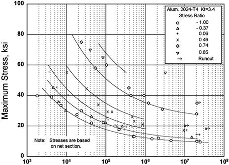
FIGURE 5-6 Figure 3.2.3.1.8(d) in MIL-HDBK-5J displays one of aluminum’s primary flaws – no clear endurance limit. (Figure from MIL-HDBK-5J)
Consider a structural member made from a 2024 aluminum alloy, whose limit tensile stress is 47,000 psi. Further assume it reacts a cyclic load ranging from −30,000 to 30,000 psi. Clearly the stress is well below the yield limit and, therefore, at first glance, intuition would hold that since the load is lower than the limit tensile stress, the cyclic loading could be applied indefinitely. However, common sense is sometimes a poor measure of reality. It turns out that the structure can only be exposed to this load a finite number of times, perhaps some 100,000 times. If such a part belonged to an engine that rotated at a rate of 2500 RPM, it should be expected to fail in only (100,000 cycles/2500 cycles per minute) or some 40 minutes. The implication of this law is that structures made from such material need far more material than required to react the maximum loads – the structure must be heavier than a static stress analysis would indicate. The lifetime limitation of a critical aluminum structure requires such cyclic loads to be taken into account during detail design. For this reason, all aluminum aircraft structures have limited operational life, no matter how low the stress level, further requiring regular inspection of the structure.
The greatest challenge in evaluating the fatigue life of a structure is to define the loads that act on the aircraft. The problem is compounded by the fact that the load varies rapidly during each flight. On a calm day, the airplane will experience less load excursion due to gusts than on a bumpy day. Additionally, the frequency and magnitude of the loads will depend on how the airplane is used. For instance, a trainer will experience hard landings far more frequently than a professionally flown transport aircraft. In order to account for this variety, airplane fatigue loads are based on so-called load spectra. A load spectrum diagram is used to indicate the probability of a particular airplane experiencing given load levels during its lifetime. For instance, an ordinary normal category airplane (see Table 1-2), designed to operate for a 12,000 hour life, might be expected to reach 3.8 g once or twice in its lifetime. It may experience 1.5 g several thousands of times.
The FAA published the report AFS-120-73-2, Fatigue Evaluation of Wing and Associated Structure on Small Airplanes [3], in 1973. The purpose of the report is to provide methods for estimating the safe life of an aircraft structure. It is often the first step toward determining the life expectancy of the airplane. It provides scatter factors and load spectra for various types of aircraft and operation (e.g. taxi loads, landing impact loads, gust and maneuver load, etc.). These factors and load spectra are used to develop the probability that structural components, such as wing or tail, could reach the end of their design life (in terms of ground-air-ground cycles) without developing detectable fatigue cracks.
Stress corrosion is a phenomenon that occurs to ductile alloys that are exposed to high tensile stresses in a corrosive environment. Examples of corrosive environments include water vapor, aqueous solutions, organic liquids, and liquid metals. The corrosion manifests itself as cracking along grain boundaries in the material. Research shows that aluminum alloys that contain substantial amounts of soluble alloying elements, primarily copper, magnesium, silicon, and zinc, are particularly susceptible to stress-corrosion cracking. Examples of such alloys include 7079-T6, 7075-T6, and 2024-T3, which comprise more than 90% of the in-service failures of all high-strength aluminum alloys [4].
Galvanic corrosion occurs when two electrochemically dissimilar metals are in close proximity to one another in a structure, for instance, when aluminum is joined to steel. Besides the electrochemical dissimilarity, an electrically conductive path between the two metals must exist to allow metal ions to move from the metal that acts as the anode to the one that acts as a cathode. While this is primarily an issue during detail design, the aircraft designer must be aware of potential implications stemming from insisting on dissimilar metals being joined in the airframe. Of course, joining dissimilar metals is frequently done in the aviation industry, but this should be avoided when possible. The galvanic corrosion problem can be remedied by applying special plating or finishing to the metals as a protection.
Table 5-3 lists several aluminum alloys commonly used in GA aircraft structures in the aviation industry. The designer should regard these as alloys for primary and secondary structures.
TABLE 5-3
Typical Applications of Aluminum Alloys in GA Aircraft
| Aluminum Alloy | Typical Application |
| 2024-T3, 2024-T4 | Used for high-strength tension application such as wing, fuselage, and tail structure. Has good fracture toughnessa, slow crack growth, and good fatigue life compared to other aluminum alloys [5, p. 102]. |
| 6061-T6 | Used for resilient secondary structures such as access panels, piston engine baffles, cockpit instrument panels, etc. |
| 7075-T6, T651 | Used for high-stress applications similar to those of the 2024. It is stronger than 2024, but has lower fracture toughness and fatigue resistance. |
aMIL-HDBK-5J defines fracture toughness as “The fracture toughness of a material is literally a measure of its resistance to fracture. As with other mechanical properties, fracture toughness is dependent upon alloy type, processing variables, product form, geometry, temperature, loading rate, and other environmental factors” [2].
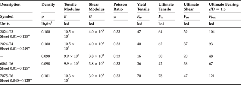
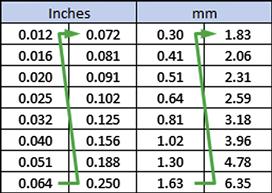
Table 5-4 shows selected properties for a few aluminum alloys that are frequently used in GA aircraft. Table 5-5 shows common sheet thicknesses of commercially available aluminum alloys. Note that to save space, the sheet thicknesses are stacked in two columns for each unit.
5.2.3 Steel Alloys
The superior strength of steel often renders it the only material fit for use in highly stressed regions of the airplane. Among frequent use are the landing gear, engine mounts, high-strength fasteners, and many other mechanical parts for which durability and strength are essential.
By definition, steel is iron (Fe) that has been modified through the introduction of alloying elements, such as nickel (Ni), vanadium (V), cobalt (Co), chromium (Cr), magnesium (Mg), molybdenum (Mo), carbon (C), and other elements. The introduction of these elements has a profound and very desirable effect on the properties of the iron and practically converts it into a new material that is in all very strong, stiff, and durable. These properties can be further enhanced through the introduction of processes such as annealing, quenching, cold working, and heat treating. The branch of materials science that deals with such processes is called metallurgy and since it is beyond the scope of this text, only an elementary introduction will be given (see, for example, Ref. [6] for more detail).
In general, metallurgical processes allow specific properties, such as hardness, ductility, toughness, and so on, to be modified. For instance, annealing is a process in which the metal is heated to a specific temperature, where it is kept for a given time, after which it is cooled at a specific rate. This process relieves stresses that may be in the material and “softens” it (makes it more ductile and less hard) so it is easier to cut, stamp, or grind. Quenching is the rapid cooling of steel and produces grain structure that is particularly hard. It is used for a class of steels called low-carbon steels and the austenitic stainless steels. This improves the durability of the steel and makes it ideal for use as highly loaded precision parts. Cold working is used to increase the yield strength of a metal. This can be done by methods such as cold rolling, cold extrusion, and cold drawing, to name a few. Heat treating is a process in which material is heated and cooled at specific rates in order to modify the arrangement of their molecular structure. It is the primary way steels other than the low-carbon and austenitic stainless steels are strengthened.
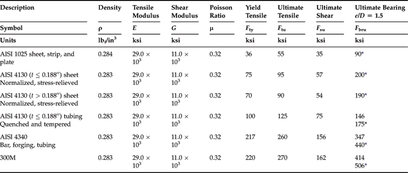
The properties of a selection of commonly used steels are presented in Table 5-6. Of these, AISI 1025 is a general-purpose steel used for various shop projects, such as to make jigs, fixtures, mock-ups, and similar. Generally, the steel is not used for operational aircraft, although it is possible to get it in an aircraft quality. Steels such as AISI 4130 and 4340 are also known as “chromoly,” as they contain traces of both chromium and molybdenum. Because of the reliable heat-treating practices and processing techniques for these steels they are very common in aircraft construction, where they are used for engine mounts, landing gear, truss fuselages, and other high-stress components. They are readily available as sheet, plate, and tubing stock.
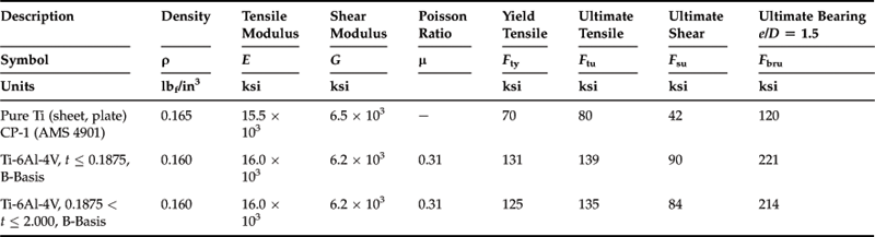
5.2.4 Titanium Alloys
Titanium is a great choice for applications that require high strength and light weight in a demanding environment. It is a relatively lightweight metal that has good strength-to-weight ratio, low coefficient of thermal expansion, good toughness, and good oxidation resistance. It also has a higher melting point than steel (1660 °C versus 1650 °, respectively). The metal was discovered in 1791 by a British chemist, William Gregor (1761–1817), and then independently again in 1793 by the German chemist Martin Heinrich Klaproth (1743–1817). The metal is one of the most abundant elements in nature, although it is expensive to extract and isolate. Today, it is found in a large array of applications, ranging from engine components and airframes to various biomedical implants, as well as golf clubs [7].
The properties of a selection of commonly used titanium alloys are presented in Table 5-7. Titanium is almost always alloyed with aluminum for use in aircraft structures. Among several common titanium alloys are Ti-6Al-4V and Ti-4Al-4Mo-2Sn-0.5Si, of which the former is thought to be the most widely used [5, p. 109]. In addition to titanium (Ti), it contains 6% aluminum (Al), 4% vanadium (V), and a trace of iron (Fe) and oxygen (O). The first large-scale use of this material was in the production of the famous Lockheed SR-71 Blackbird reconnaissance aircraft. The development of the aircraft, as well as that of the now infamous North American XB-70, solved many of the production problems accompanying its use and made it a suitable alternative to aluminum alloys that offers greater strength, stiffness, competitive weight, and high heat resistance. Of course, all this comes at a higher price. At the time of writing, the price of pure aluminum was in the $2.5 per kg range, but titanium remained just shy of $9 per kg [8]. This price renders its competitiveness limited in the GA industry and makes it a material resorted to for special requirements.
5.2.5 Composite Materials
In the aircraft industry, the term composite applies to structures that consist of more than one constituent material so the combination yields properties that are superior to those of the constituent materials. Composites are a large and disparate class of materials, ranging from steel-reinforced concrete used for buildings to stiffened plywood-balsa-plywood sandwich panels used in airplanes. Nowadays, when it comes to aircraft, composites almost exclusively refer to various fiber-reinforced plastics that are used as both primary and secondary structures. It is essential that the aircraft designer is familiar with the numerous terms that are used in industry. This article defines and explains most of the common terminology used by engineers and technicians.
Types of Composite
There are three common forms of composite used for industrial applications:
1. Fibrous composites, which consist of fibers embedded in a matrix (resin). FRPs are examples of this.
2. Laminated composites, which consist of layers of various materials. Composite sandwich panels are the best examples of a laminated composite. Such composites are simply referred to as laminates and the constituent layers are called plies.
3. Particulate composites, which are composed of particles in a matrix. Steel-reinforced concrete is an example of this. At the time of writing, particulate composites are not used to construct airplanes and will thus be omitted from further discussion.
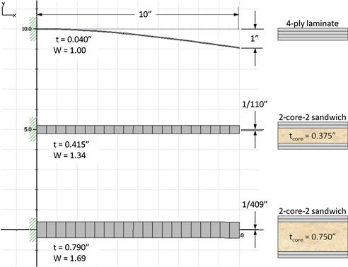
In its most basic form, composites consist of layers of fibers in the form of a cloth that are impregnated with some type of plastic matrix (or resin) and then cured to form a rigid structure. An example of this is fiberglass cloth embedded in epoxy resin. This is how the so-called fiberglass-reinforced plastics (FRP) and carbon-reinforced plastics (CRP) are prepared. Sometimes a third constituent material, called a core, is added to fabricate the so-called composite sandwich. The purpose of the core is to separate the plies by a given thickness and that way increase the stiffness of the structure. The resulting panels are light, stiff, and strong and are ideal for use as skin for wing, HT, VT, or fuselage structures. Panels so stiffened allow multiple ribs and frames to be eliminated from the structure, simplifying the airframe.
To better understand the potential the core has in the stiffness of composites, consider Figure 5-7, which shows three 10′′ long cantilevered composite beams. The top one is a simple 4-ply laminate consisting of typical aircraft-grade fiberglass laid up using a [+45°/−45°]S layup (S stands for symmetrical). The center and bottom ones feature the same fiberglass layup, with the addition of a 0.375′′ and 0.75′′ core, respectively. The resulting thicknesses and normalized densities (the density of the bottom beam is 1.69× that of the top one) can be seen in the figure. Then, some load is applied to the tip (right end) of the laminates such that the top one deflects 1′′. Applying the same load to the center and bottom beams would cause them to deflect 1/110′′ and 1/409′′ respectively. This means that the bending stiffness of the center beam is 110× greater and the bottom one is 409× stiffer than the top laminate. The huge increase in stiffness only costs a very modest increase in weight.
Structural Analysis of Composite Materials
There are two approaches used to perform structural analysis of composite materials; micro- and macromechanics. Micromechanics examines the interaction of the constituent materials (i.e. of the fibers and matrix) on a microscopic level. One of the outputs is the predicted “average” properties (such as strength and stiffness) of a composite laminate in terms of the properties and behavior of the constituent materials. Another one is the prediction of the distributions of stresses and strains in the laminate on a ply-to-ply basis.
An example of the capability of micromechanics is shown in Figure 5-8. A 6-core-6 sandwich with an unsymmetrical layup [+45°/+45°/0°/+45°/0°/+45°]S with bi-directional cloth is subjected to pure bending. The three left columns show strains in the composite as a whole, whereas the three right columns show strains in each of the plies making up the composite. The darker shaded region on the top and bottom of each column is the fiberglass plies and the lighter and thicker (taller) center region represents the thickness of the core (0.375′′). Considering the composite strains it can be seen that the moment creates strains identical to those predicted by classic solid mechanics theory. The moment (applied about the x-axis) creates strain about both x- and y-axes through Poisson’s ratio. However, when considering the ply strains, it can be seen that the largest strains are picked up by the four 0° plies and the core. The core has a very low modulus of elasticity (Young’s modulus) so it can stretch quite a bit without the formation of large stresses. The plies, on the other hand, have a very high modulus of elasticity, so the four 0° plies will generate substantially larger stresses than the +45° ones. As a consequence, if the applied moment becomes large enough, they are the first plies to fail. The application of micromechanics further allows the structural analyst to evaluate whether, if this happens, the remaining six plies will be capable of reacting the moment, or will fail subsequently. That sort of analysis is called residual strength analysis and is a standard procedure in the development of composite aircraft.

FIGURE 5-8 The effect of a pure bending moment on the strains (and therefore stresses) in a 6-core-6 laminate. The thicknesses of the core and plies is proportionally accurate.
Macromechanics is the study of composite materials assuming they can be approximated as if they were homogeneous and the effects of the constituent materials are detected only as averaged apparent properties of the composite. This way, composite structural members are treated almost as if they were isotropic (except with different properties along each material axis), yielding a convenient analysis workaround for use in finite element analysis software.
The structural analysis of composites is performed using the classic laminate theory, which allows the prediction of stresses and strains in composite laminates. Among others, Tsai [9] and Jones [10] provide a good treatise of the theory. It is based on the following assumptions:
• The material is orthotropic.
• Ply properties are linearly elastic.
• There is no coupling between the normal and shear strains, ε and γ, or the normal and shear stresses, σ and τ. In the case of a unidirectional composite, where the stress/strain coordinate axes are referred to as the principal material directions, the assumption is justified on the basis of material symmetries.
General directions of the stress and strain axes are denoted as shown in Figure 5-9. Then, material properties in the principal material directions 1, 2, and 3 are as follows:
E1, E2, and E3 = Young's (elastic) moduli in the principal material directions
G23, G31, and G21 = shear moduli
νij = Poisson's ratio for transverse strain in the j-direction, when stressed in the i-direction.

The examples presented in Figure 5-7 and Figure 5-8 are prepared using the theory.
Pros and Cons of Composite Materials
FRPs offer many benefits over traditional materials, among which are high strength, light weight, flexibility in design, ease in the fabrication of compound surfaces, part consolidation, high dielectric strength, dimensional stability, and corrosion resistance. At this time, composites are being used in a seemingly endless number of applications, ranging from recreational boats, where they have practically replaced other traditional building methods, to aircraft. In the aircraft industry, composites are exceptional because of a favorable strength-to-weight ratio and the ease with which compound surfaces can be fabricated. Such surfaces are essential for drag reduction in aircraft. Due to good electrical insulating properties composites are also ideal for use in appliances, tools, and other machinery. Furthermore, they are corrosion-resistant and offer extended service life over metals. The author has had an experimental composite structure exposed to the elements since 1989 to evaluate this aspect of composites. When last inspected, degradation was impossible to detect visually, although admittedly no coupons have been pulled off this structure to validate whether the strength properties have changed. Overall, in addition to high tensile strength, glass fibers offer excellent thermal properties, as well as great impact- and chemical-resistance characteristics.
FRPs also come with disadvantages. To begin with, the resin is highly toxic; if not handled with care, it can easily result in serious dermatitis. It is also subject to storage limitations, strength variability, and impact sensitivity, all of which may cause serious strength degradation. Impact may also cause delamination, which is a separation of plies that results in strength, stiffness, and buckling issues. It is a serious flaw that composites tend to fail with limited warning. Metals, in contrast, fail only after an inelastic elongation. The strength of composite structures is vulnerable to fabrication flaws such as wrinkling, bridging, and dry fibers which will compromise its strength. In the professional manufacturing environment, the structure is carefully inspected against these, which adds cost to the production. Composites are notoriously poor in bearing and require careful attention to cleanliness during the construction process. Additionally, they often require specific surface finish requirements. For instance, FRPs and CRPs require light colors, preferably white, on surfaces exposed to sunlight to minimize heat absorption. Heat can be very detrimental to the strength of the resin being used. As a consequence, their operational temperature limits are well below that of aluminum, which is not that great to begin with. Additionally, the fact that FRPs are good electrical insulators makes them very vulnerable to catastrophic failure if struck by lightning. This is particularly critical to airplanes and calls for specific methods to carry electrical current by the introduction of metal conductors that have to be co-cured with the composite. To add insult to injury, these conductors are typically a “one-shot deal.” They have to be replaced upon landing, unless of course a second flash of lightning strikes first.
Fibers
While it is this combination of matrix, fiber and manufacturing process that gives the composite its superior performance, it is helpful to consider these elements separately.
It is primarily the glass fibers that are embedded in the resin that account for the strength advantage FRPs have over unreinforced plastics. Fibers typically come in three forms: uni-directional, bi-directional, and as fiber mats. The first two are shown in Figure 5-9. Fiber mats are chopped strands of fibers that are randomly assembled into a cloth. They are not to be used for primary structures in aircraft as their strength and stiffness properties are unacceptably poor. On the other hand they are acceptable as secondary structures provided the ply thickness is low enough. Fiber mats are commonly used for boats, swimming pools, and jacuzzis.
The fibers play an imperative role in a composite structure reacting loads. Since the fibers are much stiffer than the matrix, the load inevitably is reacted by the fibers. The resin matrix, in contrast, serves to distribute the load among the fibers, besides retaining the intended shape of the structure. Several types of fibers are available commercially, of which the most common are introduced below:
Aramid fibers: a class of very strong, lightweight, and heat-resistant multifilament fibers used for a myriad of applications ranging from bulletproof vests and helmets to parachute tethers. Introduced in 1961 by the DuPont Company. They are widely used in the aerospace industry, for instance, under the name Nomex.
Boat glass: a name commonly used to identify fiberglass used for boat construction. It is also called fiberglass mat or, simply, glass mat. Boat glass consists of fiberglass chopped into short strands that are then pressed together to form a mat. The mat offers far more uniform properties than uni- or bi-directional fiberglass, only much poorer. The glass mat requires approximately 1.5 to 2 times its own weight in resin to be fully saturated.
Boron fibers: boron is a class of sophisticated fibers that are high-strength and lightweight. They are widely used in various advanced aerospace structures, for instance in aircraft such as the F-14, F-15, B-1 Lancer, and even the Space Shuttle. They are also found in bicycle frames, golf shafts, and fishing rods.
Carbon fibers: another advanced high-strength, high-stiffness, and lightweight fiber used in a variety of applications, ranging from baseball bats and bicycle frames to automotive and aerospace vehicles.They are used in micro air vehicles (MAVs) as well as the fuselage of the new Boeing 787 Dreamliner. Carbon fibers are also known under the name graphite. The primary drawback of laminates made from carbon fibers is their vulnerability to damage, which is compounded by the difficulty in detecting damage visually.
C-glass: specially developed to provide good corrosion resistance to hydrochloric and sulfuric acid. It gets its name for this property, which is short for corrosion-resistant fiber.
E-glass: the most popular type of fiberglass and typically the baseline when comparing composites. In particular, E-glass offers good strength properties at a low cost; and it accounts for more than 90% of all glass fiber reinforcements. Named for its good electrical resistance, E-glass is particularly well-suited to applications where radio-signal transparency is desired, as in aircraft radomes and antennae. E-glass is also used extensively in computer circuit boards to provide stiffness and electrical resistance. Along with more than 50% silica oxide, this fiber also contains oxides of aluminum, boron and calcium, as well as other compounds.
Graphite fibers: see carbon fibers.
Kevlar®: the registered trademark of a version of aramid fibers developed by DuPont in 1965. The resulting fibers are extremely strong and resilient and are probably best known for their use in body armor and military helmets. It sees wide use in the civilian aviation industry as well as, for instance, as rotor-burst protection in jet engines, and even as the risers in the Cirrus Airframe Parachute System (CAPS) in the Cirrus SR20 and SR22 aircraft.
R-glass (AKAS-glass or T-glass): a type of fiberglass that offers greater strength (∼30%) and better temperature tolerance than E-glass. It is primarily used for aerospace applications. Also called high-strength glass fiber. When greater strength and lower weight are desired, S-glass is a possible candidate instead of other advanced fibers, such as carbon. High-strength glass is generally known as S-type glass in the USA; it is often called R-glass in Europe and T-glass in Japan. Originally developed for military applications in the 1960s, a lower-cost version, S-2 glass, was later developed for commercial applications. High-strength glass has appreciably higher silica oxide, aluminum oxide, and magnesium oxide content than E-glass. Typically, S-2 glass is approximately 40% to 70% stronger than E-glass.
S-2 glass: can be used as a substitute for E-glass. In comparison, it has higher tensile and compressive strength, is stiffer, and exhibits improved impact resistance and toughness. In the aviation industry, S-2 glass is used for helicopter blades, aircraft flooring and interiors, but it can also be found in applications well beyond aviation. Like C-glass, it has good corrosion resistance to hydrochloric and sulfuric acid.
Resin
The purpose of the resin is to bind the fibers together into a single structural unit and, in the process, distribute strains among them while protecting them from the elements. Generally, there are two kinds of resin: thermosets and thermoplastics. The difference depends on the chemistry of the polymers, both of which contain highly complex molecular chains. In the case of thermosets, as the resin cures, molecular chains crosslink to form a rigid structure that cannot be changed through the further application of heat; the final product is irreversible. Thermoplastics, on the other hand, can be processed at higher temperatures; they can be reheated and reshaped more than once; the final product is reversible.
Thermosets
This is the resin used for aircraft structural applications. They are relatively inexpensive, simple to use, and offer good mechanical and electrical properties, as well as resistance to the elements. They are best known as a plastic that once cured cannot be converted to it original state (contrasting thermoplastics) The most common resin thermosets are listed below. It is a drawback that they ususally cure during an exothermic chemical process. They have a stable shelf life of several months, but when mixed with the proper catalyst (“hardener”), cure within minutes.
Epoxies: the most common resin used for aerospace applications. The nickname “epoxy” comes from its chemical name “ployepoxide.” Epoxies are more expensive than the polyesters but offer greater strength and stiffness, as well as less shrinkage. They are highly resistant to solvents and alkalis and even some acids. They are easily incorporated into most composite manufacturing processes and allow specific properties, such as chemical or electrical, to be modified through the proper catalyst. Some common types of epoxy resins for aircraft use are: Safe-T-Poxy, which was especially developed to reduce the development of dermatitis, a common allergic reaction. It is no longer produced, and has been replaced by a new resin called E-Z Poxy, which offers the same handling and physical properties. MGS Epoxy, is used for certified aircraft applications; AlphaPoxy, is used for secondary structures; and Aeropoxy, is used for primary structures. Also well known are Rutan Aircraft Epoxy (RAE) systems.
Phenolic resins: used for a multitude of applications, some of which take advantage of their high temperature tolerance (brakes, rocket nozzles). Used to impregnate Nomex honeycomb floors and interior cabin liners in some aircraft, where it meets smoke, combustion, and toxicity requirements.
Polybutadienes: have great electrical properties and chemical resistance and as such are used for radomes as an alternative to E-glass/epoxy laminates. High resilience renders them a popular choice in the production of tires.
Polyesters: used for a multitude of applications, such as boats, bathtubs, and auto body parts. Polyester resins are solvents for many types of synthetic foams (see below), so the user must make sure the proper core is used if making composite sandwiches.
Polyurethanes: can be formed into either thermoset or thermoplastic resin. As a thermoset, it is primarily used for applications involving automotive bumpers.
Vinylesters: are used for many of the same applications as polyesters, but are more expensive. They are better than polyesters in applications exposed to high moisture environment, such as for boat manufacturing.
Thermoplastics
They are less widely used for aviation applications than thermosets. Their best-known property is that when heated they become liquid, but then return back to a solid state when cooled. The property renders the material highly practical for all sorts of applications, ranging from soda bottles, nylon garments, monofilament fishing lines, to engine fuel lines. Thermoplastics can be melted and frozen repeatedly, rendering them recyclable.
Sandwich Core Materials
The sandwich core can be made from a multitude of materials, although with some constraints. First, the resin must not be a solvent for the core; and second, it has to be resilient enough to not fail before the fiberglass. The following materials are well suited for use in aircraft composite sandwiches, although some are not used for certified aircraft:
Urethane foam: costly, but easy to work with. It is impervious to most solvents and can thus be used with less expensive polyester resin. It can easily be cut and carved to shape, and then sanded to shape with bits of itself [12]. It is useful for making wingtips and fairings in homebuilt aircraft, as well as compound surfaces. Readily available in sheets that are 24′′ × 48′′, in thicknesses from ½′′ to 2′′, at 2–4 lbf/ft3. It gives off toxic fumes when it melts and should not be used to hot-wire (see later). Not used for certified aircraft.
Clark foam: more expensive and dense (4.5 lbf/ft3) variety of urethane foam. Renowned for versatility and famous for use as core in surfboards. Not made since 2005. Not used for certified aircraft.
Styrofoam: blue-colored styrofoam is the most popular material for use as core in wings of homebuilt aircraft and is also used for insulation in homes. Readily available in sheets that are as large as 48′′ × 96”, in thicknesses from ¾′′ to 4′′, at 2 lbf/ft3. Not used for certified aircraft.
Polystyrene: commonly used for marine applications, it is also used as core in the wings of several homebuilt aircraft. Well known for its use as insulation in homes and as packing material. Easily recognizable as the aggregate of small foam balls. It is very susceptible to solvents and will be ‘eaten’ by polyester resin. Available in blocks that are as large as 14′′ × 109′′, and 7′′ thick, at 1.6 to 2.0 lbf/ft3. Not used for certified aircraft.
Klegecell®: registered trademark for a PVC foam that meets all FAA regulations for fireproof aviation materials. Has been in production for over 50 years. Unaffected by UV rays and very stable with respect to resins. Has extremely high strength-to-weight ratio, excellent thermal and acoustic insulation properties, low water absorption and good chemical resistance. Available in sheets that are as large as 48′′ × 96′′, in thicknesses from ¼′′ to 2′′, at 3–6.25 lbf/ft3. Used for certified aircraft.
Divinycell®: registered trade mark for a PVC foam that also meets all FAA regulations for fireproof aviation materials. Unaffected by UV rays and very stable with respect to resins. Available in sheets that are as large as 48′′ × 96′′, in thicknesses from ¼′′ to 2′′, at 3–6 lbf/ft3. Used for certified aircraft.
Honeycomb: Honeycomb refers to a class of materials used as sandwich cores in which thin material, ranging from paper to alloys, is formed into hexagonal cells to use as core. Honeycomb can be used for both flat and curved panels, however, bonding fibers to the comb is more difficult. There are three relatively well known types of honeycomb: (1) aluminum honeycomb, which has one of the highest strength-to-weight ratios of any structural material; (2) Nomex honeycomb, which is made from Nomex paper dipped in phenolic resin and is widely used in the aviation industry; and (3) thermoplastic honeycomb, which is used in a multitude of transport applications. Used for certified aircraft.
Glass Transition Temperature
In terms of FRPs and GRPs, the glass transition temperature, TG, refers to the temperature at which the resin transitions from a hard and relatively brittle state into a molten (or soft) state. Reaching this temperature in operation could be catastrophic to a primary structure as it renders the laminate incapable of reacting the applied loads. Most FRPs and GRPs used for aviation applications have a TG in excess of 180 °F.
Gelcoat
Gelcoat is what provides the glossy, high-quality finish on the exposed surface of FRPs and GRPs. It is a polyester or epoxy resin specifically prepared with chemicals to control viscosity and cure-time, as well as pigment with the desired color. Gelcoat is sprayed into the mold ahead of the plies being laid up.
Pre-cure
Pre-cure is a term used for flat laminated plates that are cured prior to being used as a supplemental structural material. Think of it as a flat sheet of aluminum alloy, except it is made from FRP. Having these at one’s disposal is priceless, as one can cut them to a desired shape, and then co-cure them with a laminate layup. Pre-cures are frequently used to place hard points in a sandwich laminate, through which metal fasteners may be used. Their thickness is then equal to the thickness of the core. This will form a kind of island of solid laminate in the sandwich panel, which, as stated earlier, is ideal to provide bearing strength and transfer fastener load into the sandwich.
Aircraft Construction Methodologies
There are primarily two methods used to build composite airplanes; moldless composite sandwich construction, and molded composite construction. The former is typically used for homebuilt or kit aircraft and is a method generally thought to have been pioneered by the well-known Burt Rutan to permit customers to fabricate the experimental Rutan VariEze and LongEze kit planes [11]. The method is explained in detail by Lambie [12] and Clarke [13]. The first step in the application of the method is to “preform” the sandwich core using a multitude of methods. Once the core has been prepared, it is covered with fiberglass cloth and subsequently impregnated with resin (or “wetlay”). The impregnation takes place by pouring resin over the cloth and then paintbrushes and squeegees are used to spread it and to wet the entire cloth. This step requires careful attention to prevent too much resin from being used. If more than one ply is required, the second ply is laid on top of the first while it is still wet, and more resin is added, and so on. The part is then allowed to cure.
The pre-forming of the core is done by a multitude of methods. It can be something as simple (but crude) as carving or sanding the foam to shape, although for parts that require greater accuracy (note that accuracy is a relative term) the foam is cut to shape using an electrically heated wire (or “hot-wiring”). While satisfactory for homebuilt aircraft, this method is never used for certified aircraft because of its inherent flaw of quality irregularity.
Instead, molded composite construction is used for certified aircraft. The method uses “female” or cavity molds that have been accurately shaped to form the outside mold line (OML) of the part. Then fiberglass cloth called “pre-preg” (because it is already impregnated with resin) is laid inside the mold. If more than one ply is required, another pre-preg is laid on top of the previous one, and so on. Once the layup has been completed, some strands of sticky putty are laid around the part and then a plastic sheet is draped over it and tacked to the putty. This encloses the part in a hermetically sealed environment (“vacuum-bagging”). Then a vacuum pump is connected to the plastic and turned on to form a vacuum under the plastic veil. This is a part of a production process to be explained in a moment. Then, the part sitting in the mold is rolled into a warming room (perhaps some 150–180 °F) where it is allowed to cure for a specific number of hours.
So, why is all of this preparation necessary?
The pre-preg is a special fiberglass (or graphite) cloth impregnated with resin under controlled circumstances. This ensures repeatability. In order to certify an airplane, the material qualities have to be repeatable. This means that the strength of the composite laminate should not vary from day to day – it should be the same no matter the time of month or position of the moon. The warming room ensures the resin cures at an optimum temperature, but this maximizes the strength of the laminate. It also lowers the viscosity of the impregnated resin, something taken advantage of through the application of pressure. With the formation of a vacuum on the part side of the plastic veil, atmospheric pressure squeezes air-bubbles out of the pre-preg and helps spread the resin uniformly throughout the laminate. Both improve the quality of the laminate, ensuring the proper fiber/resin ratio. Sometimes, rather than using vacuum, which only applies a 1 atmospheric pressure to the laminate, the laminate is brought into a pressurized container, called an “auto clave.” There it is subjected to as much as 5–10 times the atmospheric pressure.
Fabrication Methods
There are a few fabrication methods used to manufacture FRPs and GRPs that are worth presenting in this context:
Hand layup and spray up: the simplest and least expensive method to manufacture FRP or GRP parts. Plies of fibers are placed into a mold, after which it is impregnated with resin, unless the cloth is a pre-preg. The impregnation takes place either by simply pouring the resin onto the cloth and spreading it out using squeegees and paintbrushes, or it is sprayed on using special spray-guns.
Resin transfer molding – RTM: consists of a rigid heated mold that contains gelcoat, surfacing veil, and the fiberglass cloth, into which resin is pumped under pressure. The mold is typically 100–120 °F (40–50 °C). The warm and pressurized resin flows through the tool and uniformly impregnates the laminate. The primary advantage of this method is the superior surface quality of parts, as well as dimensional tolerances and consistency of parts.
Compression molding: consists of placing the material to be molded (a thermoset), preheated, in a heated open male-female mold. Then the mold halves are brought together and the material is compressed, which forcefully spreads it uniformly over the entire mold surface. Compression molding is the oldest manufacturing method used by the plastics industry.
Injection molding: the most common means of producing parts out of plastic material. Melted plastic is forced under pressure into a mold of the desired part and is allowed to cool and solidify. The method is very versatile and most plastic parts commonly found in one’s environment are made using this process.
Filament winding: filament winding is a process in which resin-wet fibers are threaded through a roving delivery device called a feedeye. The feedeye moves back and forth along a rotating mandrel with the desired shape – a body of revolution. The fibers are wound helically in this fashion until a desired thickness is achieved. The method is used to create pipes, tanks (e.g. external fuel tanks), and even airplane fuselages. The fiber angle is controlled with the rotation speed of the mandrel and typically varies between 7° and 90°. The process compacts the laminate, making vacuum bagging unnecessary.
Pultrusion: pultrusion consists of strands of fiber that are pulled through a die to form a column of some specific cross section. The operation involves pre-wetting the strands in liquid resin before they are pulled through a heated steel die. The process is analogous to forming an extrusion from aluminum alloys, except the fibers are being pulled out of the die rather than being pressed through it. The fibers are pulled through the machine using two powerful pulling clamps, of which only one pulls at a time. When the active clamp reaches the end of its track, the second clamp picks up the slack, allowing the first to get back to its initial position where it resides until it takes over when the second reaches the end of its travel.
The above, which barely scratches the surface, should demonstrate that the field of composites and plastics is booming. Selected properties of typical composite materials are shown in Table 5-8. Note that there is a large variation in properties between fiber brands, fiber volume, resin system, layup process, and other factors. The table should not be used for structural analyses – it is only presented to give ballpark values. Figure 5-10 compares the density, cost, strength, and stiffness of several composite materials (and polyethylene plastic), using E-glass as a baseline. Such a comparison matrix is helpful when selecting material for an application.
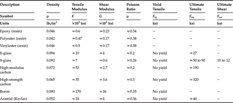
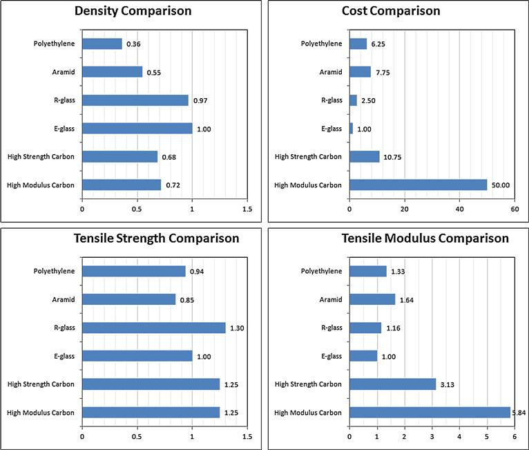
FIGURE 5-10 A comparison of several composite materials, normalized to E-glass. (Based on http://www.hexcel.com)
The reader wanting to learn more about composite materials and their use and certification in the aviation industry is directed to MIL-HDBK-17 [14], AC-20-107B [15], and AC-21-26 [16].
5.3 Airframe Structural Layout
Detailed topics in structural design are beyond the scope of this book, however, it is important to present a brief overview of structural layout to help the designer select the appropriate fabrication methodology. In modern times, there are generally four distinct construction techniques used to fabricate aircraft: wood, welded steel trusses, stiffened skin construction, and composites. The last two are most widely used, however, wood and welded trusses, while infrequent, may be the right fit for a specific design project. It is the duty of the designer to fully understand the strengths and shortcomings of the available fabrication methodologies and select the proper one for the job. This section presents the application of these methods to real aircraft and introduces both important structural concepts and challenges that are experienced in their development.
5.3.1 Important Structural Concepts
A number of structural terms are introduced in the discussion below, necessitating their brief definition [18]:
• A stiffener is a longitudinal or transverse member intended to reinforce a structure by increasing its stiffness.
• A flange is a longitudinal stiffener that runs along the edge of a flexible shell (or sheet), whose purpose is to increase the stiffness of the shell.
• A stringer is a longitudinal stiffener that is not a flange.
• A boom is a beam in the shape of a shell.
• A rib is a transverse stiffener in an open shell, or the end of a closed shell.
• A bulkhead is a transverse member in a closed shell. Strictly speaking the term includes members such as wing ribs and fuselage hoop-frames, although a bulkhead is often used for transverse members that are more substantial than frames and to which other structures attach, for instance, wing, horizontal tail, and engines.
• A primary structure is one that reacts primary loads applied to a structure. Airworthiness Circular 25.1529-1 defines it as structure that significantly contributes to the carrying of flight, ground, or pressure loads.
• A secondary structure carries significantly lower operational loads than a primary structure and is usually used for fairings and doors for unpressurized containers, for example.
• An allowable is a maximum allowable stress value of some specific material property. For instance, the ultimate tensile stress allowable for a 2024-T3 aluminum sheet of 0.125 inch thickness is 64,000 psi.
• A notched allowable is an allowable assuming it has notches in it. This always results in a reduction in the allowable, sometimes as much as 50%.
• Fail-safe means that should the primary load path in a structure fail during operation, an alternative load path exists that prevents a catastrophic failure of the structure as a whole.
Monocoque and Semi-monocoque Structure
The word monocoque comes from the Greek word mono (single) and the French word coque (shell). Monocoque is a structural technique in which stresses are reacted by a thin membrane or a shell of material, rather than a collection of beams. Such structures are stiff in bending, and light, and are therefore ideal for weight-sensitive vehicles such as airplanes. A good way to visualize a monocoque structure is to fold a sheet of paper into a cylinder and tape the free edge using something like Scotch tape. Although the resulting structure is stiff in bending this will reveal its greatest weakness – structural instability. A monocoque structure has a great tendency to fail in buckling or crippling, something easily demonstrated by a person standing on top of an empty aluminum beverage can. The empty container can support a grown man, but push the side in with a pencil with the person standing on it and the can will be compressed in the blink of an eye. This instability necessitates the addition of an internal support structure that resists these failure modes. Such a support structure is generally an assembly of frames, bulkheads, stringers, and longerons (Figure 5-11). The combination is referred to as semi-monocoque construction. Although the addition of the support structure adds to the overall weight of the configuration, it retains its light and stiff characteristics while reacting the applied loads. The advent of the monocoque structure was a major breakthrough in the development of aircraft structures. As stated earlier, such structures react the applied loads in the skin (hence the name “stressed-skin” construction).
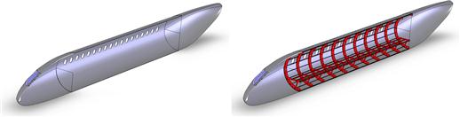
Wood Construction
Not too many aircraft are built from wood in modern times, although a few are still being operated today. The most prominent is arguably the de Havilland DH-98 Mosquito, a twin-engine, multi-role combat aircraft, made famous during World War II (see Figure 5-12). The fuselage of the Mosquito was made from a composite consisting of sheets of balsawood bonded to sheets of birch. The wing was a one-piece, all-wood construction. It featured two spars made from spruce and plywood, and the skin was a plywood sheet. A cutaway of the Mosquito can be seen in Figure 5-13, showing details of how ribs, spars, bulkheads, and skins were assembled to make this historic airplane.
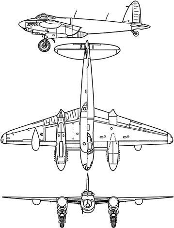
FIGURE 5-12 The de Havilland DH-98 Mosquito is arguably the most sophisticated wooden aircraft in the history of aviation.

FIGURE 5-13 A cutaway of the de Havilland DH-98 Mosquito, showing important elements of its wooden construction. Dark labels indicate aluminum and light indicate wood. (Courtesy of Raymond Ore, www.raymondore.co.uk)
The largest flying boat ever built, the Hughes H-4 Hercules, also known as the Spruce Goose, was built from plywood and to this day boasts the largest wingspan of any aircraft in the history of aviation. Its wingspan of 97.5 m (320 ft) is larger even that of the world’s current largest aircraft, the Antonov An-225 Mriya (with 88.4 m or 290-ft wingspan). Well-known examples of GA aircraft made from wood are the Bellanca Viking (designed in 1960) and various types of aircraft made by Jodel (originating in 1946) and the Robin DR400. Additionally, there are a number of kit planes for amateur builders that feature wooden construction.
As with everything, constructing aircraft out of wood has pros and cons. Among the advantages of wood are availability, affordability, comparable strength and good impact resistance, and it is usually easy to work with. Among the disadvantages are inconsistent material properties; crack growth (splitting); low Young’s moduli; possibility of rotting and even termite infestation; flammability; water absorbability (moisture variation); reduction in strength if moisture content exceeds fiber-saturation; and sensitivity to grain direction (anisotropy).
Plywood is an excellent structural material for use in wooden aircraft. It is usually made from an odd number of thin sheets (plies), each oriented at a 90° angle to the adjacent ply. The primary advantage is it offers bi-directional material properties, in addition to offering greater resistance to splitting and much-improved dimensional stability with moisture content. Plywood used in aircraft must comply with standards set by MIL-P-6070, which requires it to be tested for dimensional discrepancies, glue strength, strength properties, and others. Plywood is typically used for wing skin, fuselage skin, ribs, and frames. Common types of plywood for use in aircraft are made from birch, poplar, fir, maple, and mahogany.
Parts made from wood are primarily joined by two means: bonding and mechanical joints. The use of joining shapes (such as lap-joints; tongue and grooves; tenon and mortise, etc.) is not recommended as these invariably lead to stress concentrations that may ultimately lead to failure. Milling or routing parts is acceptable if corners are rounded. Wooden parts require special protection internally, as well as externally.
The adhesive typically used is called Aerodux-500 Resorcinol Adhesive. It is a water- and boil-proof resorcinol/formaldehyde adhesive designed for use in structural wood beams. It requires a hardener to cure, mixed in the ratio 1:1, and can cure at temperatures as low as 7 °C (45 °F).
The reader interested in designing an aircraft constructed from wood is directed toward the documents ANC-18 Design Of Wood Aircraft Structures [19], a classic text on best practices and structural analysis of wooden structures, and NACA R-354 [20], a 34-page report with tips regarding selection and the properties of wood.
Steel Truss Covered with Fabric
Many aircraft feature a fuselage consisting of a truss structure made from steel tubes welded to form a stiff, strong, and light structure. Normally, the truss (see Figure 5-14) is then covered with fabric and dope. Such fuselages are usually made from straight sections of steel tubing (nowadays from 4130 chromium-molybdenum steel) and, more often than not, are rectangular in shape. While robust, such a structure is not exactly ideal for low-drag fuselages. This is not to say that there are not low-drag aircraft around that feature such a structure. As an example, the German Scheibe SF-25 Motor Falke motor glider features a steel truss fuselage structure, although it is an exception to the rule. The method is commonly used for aerobatic and agricultural airplanes, which take a severe beating operationally and for which the truss structure serves well.
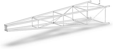
Aluminum Construction
Aluminum remains the most common aircraft construction method at the time of writing. Stressed-skin construction has revealed itself as a very efficient means of producing aircraft, thanks to a sheet metal skin riveted to sheet metal frames and bulkheads. Such a structure is very light and stiff, and the industry has developed a large number of impressive tools and techniques to put together aircraft in a short time. The stressed skin means that shear, torsion, and bending loads are reacted by the skin, which is stabilized (made less susceptible to buckling and crippling) using frames and stringers. Of course, a part of the load is reacted by this extra structure, but the difference is that the skins actually transfer loads in the form of stresses, unlike the truss-and-fabric construction of the past.
Aluminum also offers an important benefit – damage repair is relatively straightforward. As such it is surprisingly forgiving of damage, although some would argue it is relatively susceptible to damage. However, the number of parts required to assemble such aircraft is usually significant. This is due to the fact that the aluminum is in the form of thin sheets that are folded and cut to specific shapes before being riveted together. The thickness of the aluminum sheets renders it very flexible. Therefore, it has very limited buckling and crippling resistance, until it is stabilized using stiffeners – which are long sections of aluminum made either by folding other aluminum sheets or from extrusions.
Figure 5-15 shows a cutaway of the famous Supermarine Spitfire and reveals a large number of parts required to make this typical high-performance aluminum aircraft.
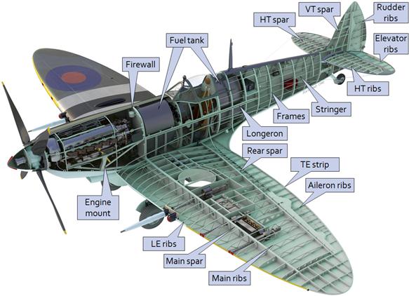
FIGURE 5-15 A cutaway of the Supermarine Spitfire, showing important elements of its aluminum construction. (Courtesy of Raymond Ore, www.raymondore.co.uk)
Composite Sandwich Construction
Composites and composite sandwich construction have already been discussed. The advent of FAA-certified aircraft such as the Cirrus SR20, SR22, Cessna Corvalis, and a series of aircraft produced by Diamond Aircraft reveals the advantage of such constructions. All feature modern tadpole fuselages and NLF airfoils, making them very efficient. For instance, the SR22 and Corvalis, both of which have fixed landing gear and wide fuselages (50 inches), offer cruising speeds that are right up there with that of rival aircraft such as the aluminum Mooney Ovation, which has retractable landing gear and a narrow fuselage (43.5- inch internal width).
The most obvious difference between composite aircraft construction and conventional wood or aluminum construction is the number of parts. For instance, the wing spar of a composite aircraft is typically a one-piece component, tip-to-tip. An aluminum structure, in contrast, consists of multiple parts: spar caps, shear webs, stiffeners, all of which are assembled using rivets. A composite wing also contains far fewer ribs, as the skins are stiffened and, thus, do not need the same number of ribs, and they are devoid of stringers. The typical composite airplane is bonded together, using an actual adhesive, something it has in common with wooden aircraft. From a certain point of view, assembling a modern composite (certified) aircraft is not unlike putting together a plastic model. The shells of components are bonded together, effectively using“glue.” Of course the analogy ends there, but the process requires far fewer parts than do aluminum aircraft.
5.3.2 Fundamental Layout of the Wing Structure
It can be argued that the wing is the most important structure of the airplane. It generates the largest aerodynamic load of all components and often features complex mechanical systems that themselves are subject to substantial loads. The wing must provide volume to store fuel, as well as to accommodate the control system required to actuate ailerons and the high-lift system. Furthermore, if the landing gear is retractable and mounted to the wing structure, the proper cutouts and reinforcement must be made to the wing to allow that function.
The wing structure is designed to react shear forces and moments that result from lift and drag. They are almost always reacted as three mutually orthogonal shear forces (lift, drag, and an inboard force if the wing has dihedral), and three mutually orthogonal moments (bending moment, drag moment, and wing torsion). To react these loads, the wing features a number of load-carrying members that have to be carefully assembled so that that the wing will be (1) geometrically symmetrical (i.e. left and right wing halves are identical mirror images of each other); and (2) as close to the intended geometry as possible. A typical wing structure is shown in Figure 5-16. It consists of the following parts (note the labeling of A through N for easier identification):
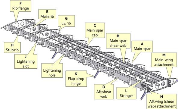
The main spar (A) is the primary load path in the wing and is intended to react wing bending and shear loads. The idealized spar consists of a relatively thin sheet of vertical structure called the main spar shear web (B). Two thicker members, called the main spar caps (C), are attached to the shear web, one along the bottom edge and the other along the top edge. The shear load reacted by the main wing spar is simply the wing lift and, by convention, the shear web is designed to react a significant part of the total wing lift. This load is distributed from the tip to the root. This load also generates bending moment and this is reacted by the spar caps. Both the shear and moment are equal to zero at the wingtip and reach a maximum value at the root. For this reason, the ideal wing spar would allow the thickness to vary from tip to root, although this is hard to do in practice, unless the spar is machined. If the spar is made from aluminum alloy, it is designed to have a stepwise reduction in shear web thickness moving from root to tip, with an increasing frequency and size of lightening holes.
Several typical main spar cross sections are shown in Figure 5-17. Note that some of the spars feature dissimilar spar cap thicknesses on the top and bottom of the spar. This is indicative of the careful nature of aircraft structural analysis – material is used only where absolutely necessary. Aircraft are generally designed to react larger forces up than down. For this reason, the upper spar cap sees higher compressive loads than the lower cap. Therefore, it must provide more meat to resist column buckling or crippling failure and is made thicker.
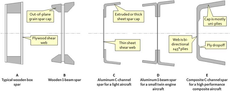
The aft shear web (D) is also a primary load path; however, it is only intended to react a fraction of the lift, with the remainder being reacted by the main spar. It also reacts the wing torsion, which is generated by the airfoil’s pitching moments, and the moment generated by the wing drag. The main spar and aft shear web split the entire lift load generated by the wing. The amount of the split depends on factors like airfoil geometry, AOA, and control surface deflection, but generally around 60–70% is reacted by the main spar and 30–40% by the aft shear web. This structural member also transfers wing torsion to the ribs and the aft attachment bracket (see later), where it is reacted as a shear force. Additionally, it reacts the fore-aft chordwise force that results from the projection of the lift and drag on the chord plane with the main spar. This force is peculiar in the sense that at high airspeed it is mostly drag that places the aft wing attachment into compression. At low airspeed and high AOA the projection of the wing lift onto the chord plane becomes larger than that of the drag and this would force the wing forward if this were not prevented by the aft attachment, which then reacts this force in tension.
This structure is also called aft spar, but this nomenclature is erroneous unless the aft attachment is designed to transfer bending moments in the form of a couple. For smaller aircraft this is very rare. The rule is that if the aft attachment has a single fastener hole it will act as a simple supported joint that only resists a shear force. In this case, the structural member is a shear web. If the aft attachment has two fastener holes it will transfer bending moments and only now is it appropriate to call it an aft spar. In this situation the aft spar (like the front one) is designed to react the entire lift force, making the structure fail-safe. A fail-safe wing structure can react the entire flight loads using either the main or aft spars. This means extra safety in the case of structural failure. Such a structural philosophy is commonly employed in passenger aircraft and is based on the fact that a statically indeterminate structure is inherently safer after being subject to damage. The Rockwell 114 and 115 aircraft are examples of light GA aircraft that feature a fail-safe wing structure.
The above discussion should show that it is very practical to take advantage of the wing structure to pick up landing gear loads for low-wing aircraft. The designer should always try to take advantage of the major load paths as this will render alternative load paths unnecessary, in turn, reducing the weight of the aircraft.
The main ribs (E) are primary structural members that extend between the main spar and the aft shear web and tie them together. As such, the ribs serve several purposes [5, p. 278]. First, they stabilize the wing skin and prevent it from buckling while reacting wing torsion. This is an imperative function for two reasons: it helps maintain the intended aerodynamic shape and the skin’s ability to transfer torsional loads. Second, the ribs shorten the effective column length of the stringers (see later), making them more resistant to column buckling. Third, they transfer wing torsion to the spars and eventually to the wing attachment hard points. Fourth, they react crushing loads due to wing bending. Fifth, they redistribute concentrated loads, such as those due to the landing gear, flap deployment, and engine pylons. And sixth, they react diagonal tension loads from the skin if subjected to skin wrinkling.
Each rib is formed so it has a rib flange (F), but these are used to rivet (aluminum wing) or bond (composite wing) the rib to the skins and spars, forming a solid structure. The rib spacing is a task accomplished during the detail design phase. Selecting the largest possible rib spacing will save weight and simplify assembly.
An important question often asked during the layout of swept-back wings is whether the ribs should be mounted normal to the main spar or parallel to the direction of flight as shown in Figure 5-18. At first glance, it would seem the latter (configuration B) is more reasonable because the rows of rivets along the skin (assuming aluminum construction) will cause less disruption to the boundary layer. However, that argument can be deflated by noting that the rows of stringers (discussed later) that extend spanwise from root to tip, and are necessary structural elements as well, will also be riveted to the skin – disrupting the boundary layer.
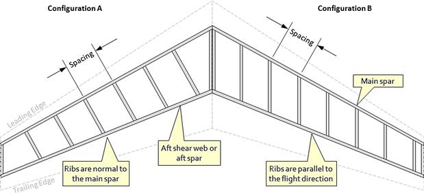
An important drawback of configuration B is that since the rib spacing is the same as that of Configuration A, the length of the ribs will be greater. Therefore, one should expect the arrangement to be heavier. Another complication is that it is actually harder to install the ribs for configuration B because they are not at a 90° angle with respect to the spar. On the other hand, the ribs belonging to configuration A are normal to the main spar (although their aft parts are not) and this offers production advantages.
In practice, both configurations are used. One reason is that configuration A is not practical next to the fuselage – it is simpler to mount the ribs parallel to it. Since the rib orientation is not usually changed immediately from B to A, it follows that a number of parallel ribs are installed before the orientation is changed. Another reason is that it might be convenient to use configuration B rib in an airplane where the engine is mounted to the wing, although this is not always the case either.
An inspection of aircraft with swept-back wings reveals that the vast majority of commercial jetliners feature all ribs that are normal to the main spar (configuration A). However, there are many exceptions where a combination of the two approaches is used. For instance, all inboard ribs of the Bombardier CRJ 1000 are parallel to the flight direction, while outside the flaps they are normal to the main spar. The Gulfstream G650 has the first six ribs parallel to the flight direction and the remaining normal to the main spar.
Another important question has to do with how the rib spacing is selected. The answer does include structural analysis, which belongs to the detail design phase and, thus, is beyond the scope of this book. However, only an elementary explanation of the process will be given. The procedure begins by assuming specific rib spacing. Then, a structural analysis that determines the material thicknesses required to react the air loads is performed. This allows the weight of the ribs and skin to be estimated. This is repeated for a few other candidate rib spacings. Eventually, a high enough number of rib spacings (a minimum of three is required to approximate the weight using a quadratic polynomial) has been evaluated to create a graph similar to the one shown in Figure 5-19. The graph shows the weight of the skin, ribs, and their combination as a function of rib spacing. If a minimum exists, as shown in the figure, it is selected for use in the wing design.
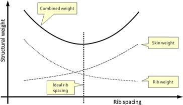
There are two additional ribs mounted to the wing that are of importance. The leading edge rib (G) is extremely important as it provides the forward shape of the airfoil. It also transfers large loads to the main spar. This happens when the wing generates lift at high AOAs. This will front-load the wing, but this means that the substantial low-pressure peaks form on the LE of the wing. This, in turn, means that most of the lift is generated by the forward part of the wing and this requires the structure to be very stout in this region.
The other rib type of interest is the stub rib (H), which is attached to the aft shear web. Stub ribs maintain the aft shape of the intended wing airfoil, while allowing control cables and pulleys to be threaded through various openings in the aileron. They also provide support to various control-system brackets and components. For instance, aileron hinge brackets are typically attached to stub ribs, which then transfer the air load to the aft shearweb. Aileron hinges are always mounted to stub ribs that have main ribs in front of them. This ensures the aileron loads are transferred more uniformly into the wing structure.
In order to keep the weight of the wing structure to a minimum, lightening holes (I) and lightening slots (J) are made in the structure. By doing this, a substantial weight of material that otherwise would simply be there for the ride is removed. Such holes and slots are far more common in aluminum and wooden structures than in composite structures, as the orthotropic nature of composites does not always lend itself well to such removal of material. Instead, composite spars allow for a more practical ply drop-off in the spanwise direction, resulting in more uniform thickness reduction, as each ply amounts to some 0.01 inch thickness. Aluminum spars for light airplanes often resort to lightening slots at the wing outboard region, as the shear and torsion have reduced significantly. Examples of such wing structures are found in many Cessna propeller aircraft.
The deployment of flaps can inflict very large loads on the wing structure that can result in a substantial increase in wing torsion. The flap load is transferred directly to the aft shear web and main spar through the flap hinges, of which the dropped flap hinge (K) is an example. Such hinges are almost always mounted right to the aft shear web and always have a stout main rib in front of them to ensure the main spar also picks up this load.
Stringers (L) are long columns of comparatively small cross section that are used to stiffen the skins and, thus, prevent them from buckling under load. For small aircraft the stringers are usually made from a folded strip of aluminum alloy sheet, whereas larger aircraft have stringers made from extrusions. And even larger (and expensive) aircraft often have integral stringers, in which the skin is machined from a thick plate of aluminum alloy so the stringers and skin are a single unit. This produces the lightest possible skin panel thanks to the efficient means by which stress is distributed throughout the panel. Additionally, the machining allows for stringers to be tapered smoothly along the span, as well as around holes and ribs [5, p. 258].
The main wing attachment (M) bracket is a primary load path and the most important hardpoint in the entire airplane. Generally, there are two kinds of attachment found in aircraft: fixed and rotary. The latter are primarily used for military aircraft with swiveling (F-14, F-111, Tornado, etc.) or folding wings (A-7, F-4, F-18, etc.) and are omitted from this text. A good discussion of those can be found in Ref. 5.
Figure 5-20 shows several methods to mount the main spar to the fuselage of the fixed type. The detailed appearance of the layouts shown varies greatly in practice and the figure should be regarded more from a stylistic perspective than precise. Configurations A, B, and C are used for high-wing aircraft. A and B are used in some commuter aircraft, e.g. Fokker F-27. The wing bending moments are fully reacted by the wing and the fuselage is effectively hanging down below it, using pinned joints. This way the fuselage does not have to be reinforced to react the wing bending moments, although it must react internal moments due to the difference in the reaction forces between the two attachment points.
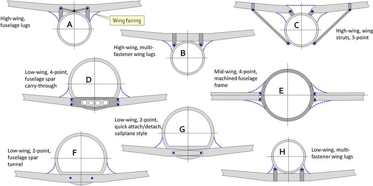
Configuration C is used by many Cessna aircraft that feature wing struts. The hard points on each wing form a triangle that is structurally rigid, although it is not fail-safe. This configuration, too, has pinned supports so bending moments are not reacted by the fuselage, although a substantial compression load has to be reacted along a line going through the lower strut pin and the wing root pin. Configuration D is used in many airplanes, e.g. the Beech Bonanza and Eclipse 500. This configuration uses a so-called spar carry-through to react the wing loads. The carry-through is by far the stiffest single structural member in the aircraft. This means that it will pick up the wing bending loads, largely bypassing the fuselage to which it is attached.
Configuration E is almost exclusively used on mid-wing fighter aircraft (e.g. F-104, F-16). The load-carrying frame requires sophisticated and costly machining from a solid ingot of alloy, making it a very expensive component to make. Additionally, a number of such frames are installed for the typical multi-spar fighter wing. Such aircraft feature the engine in the cavity between the wings, which is the reason for the selected configuration. The orientation of the fastener in the wing attachment is often normal to, rather than parallel to, the fuselage, as shown here. Configuration F is effectively configuration B inverted. It is used on the Cirrus SR20 and SR22 aircraft.
Configuration G is used in aircraft that have to be quickly assembled and dis-assembled for transportation purposes. Such airplanes include sailplanes and some homebuilt aircraft. Finally, configuration H is used in many business jets, where the fuselage sits on top of the wing. Naturally, such airplanes feature much greater structural complexity than depicted, as their attachments are statically indeterminate (fail-safe). The attachments transfer loads in a variety of ways. Some react bending moments as a force couple, others do not react them at all.
It is important to be aware of the tremendous load transferred by the wing to the fuselage structure. Figure 5-21 shows a simple example of a beam structure intended to resemble a typical cantilevered wing configuration. It is assumed this airplane weighs 2000 lbf and features a 40-ft wingspan. Furthermore, assume it is certified to the normal category of 14 CFR Part 23, which requires the airframe to be designed for a limit load of 3.8 g. The picture shows that when the airplane reacts this load symmetrically (both wings generate equal load), each attachment point transfers a shear force of 3807 lbf or 1.9 times the gross weight. When reacting an asymmetric load per 14 CFR 23.349(a)(2), which presumes one wing is generating the full half-span load and the other merely 75% (60% for aerobatic airplanes), the attachment point on the fully loaded side will transfer a shear force of 5520 lbf or 2.76 times the gross weight. This is a surprising result for those seeing it for the first time, even though it is derived using elementary statics. The purpose of the paragraph is to ensure this fact is not overlooked when designing aircraft.
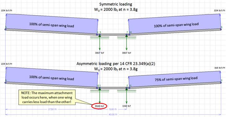
FIGURE 5-21 Reaction loads due to the aerodynamic lift generated by the left and right wing-halves of a 2000 lbf hypothetical aircraft (erroneously assuming a uniform distribution of lift). Two load conditions are shown: symmetrical (upper) and asymmetrical (lower). Surprisingly, the maximum wing attachment load is achieved when the wing carries the asymmetric 100/75 load and not 100/100 (normal and utility category).
Considering the wing layout in Figure 5-16, the entire bending moment and most of the shear force is transferred to the fuselage by the main spar. The main wing attachment must provide ample surface area for reacting wing loads in bearing and be designed such that the loads to be transferred rise gradually, rather than sharply. This means that there should be a number of fasteners present in the skin and ribs to pick up the wing load and transfer it to the main spar and then through the main spar attachment. This hardpoint reacts substantial loads, even during normal flight, rendering it very susceptible to fatigue. Consequently, the wing attachments must be analyzed and their material thickness increased beyond what is required for operational loads. There is also a concern about the dissimilarity of metals that may be used. For instance, using steel fasteners with aluminum brackets or sheets will cause galvanic corrosion and is a recipe for disaster unless proper precautions are taken [21].
The aft wing attachment (N) is a primary load path and the second most important hardpoint in the airplane. For the wing layout shown in Figure 5-16, it transfers a part of the shear force and reacts the wing torsion.
5.3.3 Fundamental Layout of the Horizontal and Vertical Tail Structures
The horizontal tail (HT) and vertical tail (VT) are aptly described as simplified versions of the accompanying wing. Compared to the wing, the loads of the HT and VT are modest. In small aircraft the structure often consists of a single spar to which a number of ribs are riveted (or bonded), and then covered with skin. Sometimes, the loads are so modest it suffices to stiffen the skin using corrugations. Examples of this can be seen in many small GA aircraft, for instance the V-tailed Beech Bonanza and many single-engine Cessna and Piper aircraft, which use corrugated skins to stiffen their elevators, flaps, and ailerons.
The main spar of light aircraft is usually placed at approximately 65–70% of the chord, selected specifically for structural efficiency. This allows the elevator and rudder hinges to be mounted directly to the spar. The Piper series of single- and twin-engine aircraft feature very simple all-movable stabilators consisting of two-spar corrugated-skin construction, designed with the main spar along the hinge line and the auxiliary spar (or stiffener) mounted closer to the trailing edge, allowing an anti-servo tab to be mounted to it.
Larger airplanes feature a single main spar and a smaller auxiliary spar. Heavy aircraft, in contrast, have an HT and VT whose load paths are structurally superior to the wings of small aircraft. Such stabilizing surfaces usually have two spars and statically indeterminate fail-safe structure.
Furthermore, the incidence of the stabilizer section of heavy aircraft is designed to be adjusted in flight, providing a powerful means to trim the airplane over a wide CG range. The incidence of the stabilizer is typically changed using a powerful jackscrew drive. The stabilizer of the Boeing 727 commercial jetliner, shown in Figure 5-22, is an example of this. The picture reveals many of the complexities inherent in advanced aircraft: redundant rudders (rudder A and B) and trim tab; vortex generators; redundant elevator trim tabs; hydraulic systems, and so on.
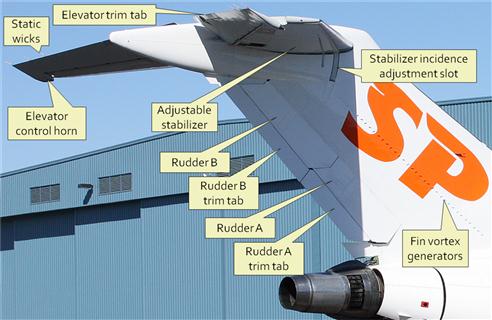
Fabrication and Installation of Control Surfaces
The HT is usually attached to the fuselage using specific hardpoints, which are fundamentally analogous to wing hardpoints, albeit simpler. Many composite aircraft bond the skin of the HT to a wide flange designed into the fuselage. This ensures the horizontal loads are transferred through a wide bond area. The VT is often an integral part of the fuselage airframe – in particular in composite aircraft. In aluminum aircraft the VT spar is sometimes integral to the aft-most bulkhead, whose purpose may be twofold; to provide a load path for the stabilizing surfaces and a means to anchor the control-system pulleys or bellcranks, which often react substantial loads.
The stabilizing surfaces typically feature symmetric airfoils, such as NACA 0008 through 0012, whose thickness ranges from 8% to 12% of the chord (as indicated by their designations). Such airfoils are low drag and yet offer volume to accommodate control system cables, pushrods, pulleys, and bellcranks. This thickness also results in a stiff structure that is free of flutter within the operating envelope of the aircraft. However, selecting a symmetric airfoil is not a rule. Some propeller-powered aircraft use either a cambered airfoil or a symmetrical airfoil at an angle-of-incidence with respect to the fuselage to reduce propeller effects (see Section 14.2, Propeller effects). Many aircraft feature symmetric airfoils such as NACA 63-008 through NACA 63-012, whose maximum thickness is farther aft than that of the double-o series, allowing the stabilizing surfaces to sustain NLF more extensively. When possible, the designer of efficient aircraft should consider such NLF airfoils for stabilizing surfaces. However, it must be emphasized this is not always practical.
It is important to bring up two issues that may lead to difficulties in the production of control surfaces. The first is the selection of airfoils that have very narrow trailing edges. Often, this is an unfortunate consequence of selecting NLF airfoils. Such airfoils often feature a cusp that makes the space between the upper and lower surfaces very small at the trailing edge. This calls for ribs so small they cannot be installed without being shortened and this may lead to a partially unsupported trailing edge, susceptible to flexing under loads. Changing from one airfoil to another on a tapered wing may require the wing skin to be stretched. If built from aluminum, this may call for costly manufacturing methods in a mass-produced aircraft. A solution often utilized is to simply ignore the cusp and replace it with a flat section (see Figure 5-23). Of course the resulting airfoil is not the one the designer initially intended. It is important to be aware of such problems and (1) avoid design solutions that are impractical from a manufacturing standpoint; and (2) ensure the production airfoils are those that are represented in the design analysis work and not the theoretical ones that are impossible to fabricate.
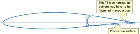
FIGURE 5-23 The manufacture of thin trailing edges is often solved by ignoring it and replacing it with a flat, rather than curved surface. Does this change invalidate the design analysis work?
The other issue also has to do with cusped NLF airfoils. The high pressure generated by the lower surface of the cusp results in hinge moments that deflect the surface trailing edge up at higher AOAs, for instance, during climb (see Figure 5-24). This invalidates the drag coefficient, modifies the airfoil and reduces the performance of the airfoil. The designer should insist that the engineers designing the flight control system are aware of such detrimental tendency.
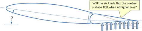
Unconventional Tails: T-tail, V-tail, and H-tail
In addition to the normal loads that a specific stabilizing assembly must react, the T-tail must react higher asymmetric loads than a conventional tail. When an aircraft featuring a T-tail yaws at a high AOA, each side of the HT generates very different normal loads. The windward side will see a high-pressure region form between the fin and the HT. The leeward side of the HT will generate much less load. This creates asymmetry in the loading on the HT that the fuselage must react in addition to the moment generated by the VT. As a consequence, the fuselage and the VT both end up being heavier than a conventional tail. Additionally, aeroelastically, the mass of the HT placed at the tip of the VT reduces its natural frequency, which, in turn, lowers its flutter airspeed. The remedy is to stiffen the VT, which again adds weight to the airframe.
Similar concerns can be raised about a V-tail. In order to achieve static and dynamic stability in a V-tail aircraft, relatively large surfaces are required. The rudder functionality of the tail requires the ruddervators on the left and right sides to deflect opposite to each other, similar to ailerons. The deflection can result in substantial forces on the two tail surfaces – one acting up and the other down. As a consequence, a large torsion is generated that the fuselage must react. The designer of V-tail aircraft must be cognizant of this effect and ensure the cross-sectional area of the fuselage in the area of the V-tail is large enough to bring the shear flow down to acceptable levels.
The H-tail brings similar complications to the empennage loads as do the T- and V-tails. Additionally, as in the case of the T-tail, the two fins placed at the tip of the HT can be considered point masses at the end of a cantilevered beam, which brings down its natural frequency and, therefore, the flutter speed. The Lockheed Electra, a twin-engine, 10-passenger military transport, designed in the 1930s, suffered catastrophic flutter of its H-tail. The designer must select thick enough airfoils to reduce the likelihood of such events.
The reader is directed to Section 11.3, On the pros and cons of tail configurations, for additional information about these and other tail configurations.
5.3.4 Fundamental Layout of the Fuselage Structure
Fuselage Structural Assembly – Conventional Aluminum Construction
A conventional aluminum semi-monocoque fuselage structure is shown in Figure 5-25 and Figure 5-26. This structure typically consists of a row of hoop-frames that are joined with stringers and floor beams and floor frames by rivets or metal bonding. A schematic of a typical cylindrical center structure is shown in Figure 5-26. The aluminum sheets that form the fuselage skin are then riveted to the frames and stringers, forming a very stiff but light structure. In this structure, cutouts must have a generous radius rather than sharp corners, as these will generate substantial stress concentrations that will significantly reduce the life of the structure.
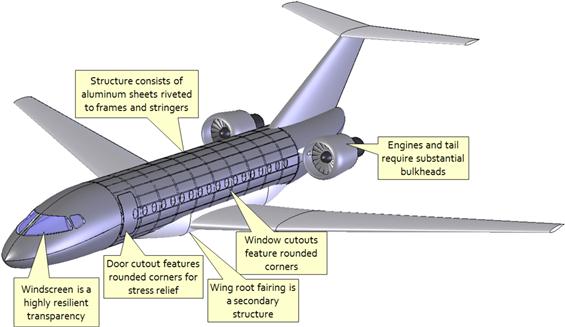
FIGURE 5-25 Typical fuselage for a passenger transportation aircraft consists of aluminum sheets riveted to an underlying rigid structure.
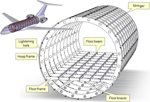
FIGURE 5-26 The underlying fuselage structure consists of hoop frames, stringers, floor frames, and floor beams (nose and tail structure is omitted).
Figure 5-25 shows a very important feature of such a structure: all cutouts feature generously rounded corners or are elliptical or circular in some airplanes. The purpose of this is to reduce stress concentrations that result from the removal of material and, thus, increase the durability (and safety) the structure.
Fuselage Structural Assembly – Composite Construction
A semi-monocoque fuselage made from composites features a significantly different philosophy. The skin is stiffened using a composite sandwich that consists of a layer of material like honeycomb or foam sandwiched between layers of fiberglass or graphite or similar. This way, the total number of frames can be reduced substantially. Such fuselages are typically made by first bonding the internal structure together and allowing it to cure. Then, this assembly is bonded as a single piece to the stiffened fuselage skin halves. The fuselage skins have joggles to which the adhesive is applied. Joining the skins' halves together properly is easier said, than done.
A common difficulty in the assembly of semi-monocoque composite fuselages is to control the thickness of the bonds (adhesive). Certified composite aircraft have to demonstrate the repeatability of the bondline strengths. This is done by the manufacturer, which assesses a range of bondline thicknesses expected to be seen during production (e.g. 0.040′′ to 0.125′′). Then, repeated strength tests of specimens using those thicknesses are performed, and this allows the strength of the bondline thicknesses to be established. Then, during production, the bondline thickness of all bonds is inspected and if found outside these limits a repair must be designed, basically using the assumption that the bondline strength is zero. Then, a technician performs the repair. It can be seen that poor production quality can cost the corresponding manufacturer a fortune. For this reason, established manufacturers perform the bonding operations using special machinery that substantially cuts down on such deviations (or non-conformances as they are called in industry).
Special Considerations: Pressurization
Tens of thousands of passenger and business aircraft operate every day at altitudes ranging from 25,000 to 51,000 ft. At those altitudes, especially altitudes above 40,000 ft, people quickly die if exposed to the outside atmosphere. For this reason, any aircraft designed to routinely operate at such altitudes must provide oxygen to the crew and passengers. Effectively, such aircraft are pressure vessels and are capable of maintaining higher pressure inside the cabin than that of the ambient atmosphere. Generally, people will begin to suffer from oxygen deficiency at altitudes as low as 14,000 ft. The individual capability varies, with some individuals capable of climbing mountains as high as 28,600 ft,3 and as low as 6000–8000 ft for people who suffer from heart problems. Requirements in 14 CFR Part 121 to supply oxygen to the occupants when operating an aircraft are stipulated in the following paragraphs:
121.327 – Supplemental oxygen: Reciprocating engine powered airplanes.
121.329 – Supplemental oxygen for sustenance: Turbine engine powered airplanes.
121.331 – Supplemental oxygen requirements for pressurized cabin airplanes: Reciprocating engine powered airplanes.
121.333 – Supplemental oxygen for emergency descent and for first aid; turbine engine powered airplanes with pressurized cabins.
However, it is paragraphs 14 CFR 23.841, Pressurized cabins, and 14 CFR 25.841, Pressurized cabins, that stipulate what capability the airframe must possess in order to sustain cabin pressure in the case of a system failure. Design guidelines are also given in SAE ARP1270, Aircraft Cabin Pressurization Control Criteria.
With respect to aircraft, requiring pressurizations inflicts serious design, manufacturing, maintenance, and operational limitations on the aircraft. It is essential that the designer becomes aware of some of these requirements as they expose a number of challenges, ranging from fuselage deformation to system and equipment installation.
Figure 5-27 shows a cabin pressurization schedule for a typical commercial jetliner. As the airplane climbs, the pressurization will immediately begin to delay the altitude reduction in the cabin. As the airplane reaches its intended cruise altitude (here 39,000 ft) the pressure difference between the atmosphere at that altitude and the cabin is about 8 psi (atmospheric pressure at S-L is 14.7 psi), but this is equivalent to an atmospheric pressure at 8000 ft, enough for all except the weakest of us to survive.
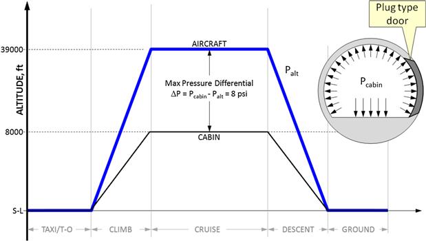
From a structural standpoint, the most efficient pressure vessel is one that reacts lateral or out-of-plane stresses as tensile stresses [22]. This implies that for a given volume, a spherical pressure vessel is the most efficient one (see Figure 5-28). However, when it comes to transporting passengers and maintaining acceptable performance, and stability and control, this geometry is not practical. The next best shape is a cylinder, which is of course a sphere that has been split along a meridional and the two halves attached to a cylinder (again see Figure 5-28). From a structural standpoint, this is the ideal shape for a pressurized aircraft, and this explains why this form prevails in the aviation industry.
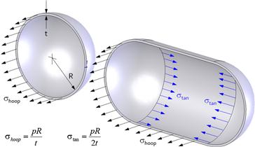
FIGURE 5-28 The difference between hoop and tangential stresses. The term p is the internal-external pressure difference. R and t are radius and wall thickness, respectively.
As shown in Figure 5-28, the sphere reacts the out-of-plane pressure load as hoop stresses only. However, the cylinder reacts it as hoop and tangential stresses. When used for fuselages, this requires an especially reinforced structure to be placed at either end of the fuselage. This structure is called a pressure bulkhead, and it must react a substantial pressure force. The layperson is often oblivious to the forces the fuselage must support which are solely attributed to the pressure differential. For instance, the typical passenger door in a commercial aircraft is 42 × 72 inches (type A door). When exposed to an 8 psi pressure differential (see Figure 5-27) the total out-of-plane force acting on it amounts to 42 × 72 × 8 = 24,192 lbf. This explains why it is so amusing when angry passengers threaten to open the doors in flight.
In all seriousness, this number depicts the robustness of the reinforcement required to hold the doors in place. A common method is to use doors that are shaped like a plug (see Figure 5-27). Such doors help distribute the pressure load around the door frame. It is sad but true that doors in pressurized aircraft are overlooked by almost anyone except the engineers who designed them. It is sad because these doors are truly a marvel of modern engineering. Not only do they have to react some 12 tons of load, when opened, most types swing to the outside of the airplane by a simply operated door handle. Think about that next time you board an airplane. How would you get a plug type door to do this feat? In addition to an immense pressurization load, cutouts for windows and doors will further cause stress concentration requiring a yet greater amount of material to sustain. The aspiring designer insisting on super-large entry doors and windows for a pressurized airplane should be very cognizant of the structural challenges this may cause. While large openings can be implemented technically, it will most certainly reduce the useful load of the aircraft.
Variables
| Symbol | Description | Units (UK and SI) |
| E | Young’s (elastic) modulus | ksi or MPa |
| Fbru | Ultimate bearing stess (per MIL-HDBK) | ksi or MPa |
| Fsu | Ultimate shear stress (per MIL-HDBK) | ksi or MPa |
| Ftu | Ultimate tensile stress (per MIL-HDBK) | ksi or MPa |
| Fty | Yield tensile stress (per MIL-HDBK) | ksi or MPa |
| G | Shear modulus | ksi or MPa |
| P | Pressure | psi or Pa |
| TG | Glass transition temperature | °R or K |
| ε | Normal strain | in/in or mm/mm |
| γ | Shear strain | in/in or mm/mm |
| μ | Poisson ratio (per MIL-HDBK) | |
| ν | Poisson ratio | |
| ρ | Density | lbf/in3 or kg/m3 |
| σ | Normal stress | psi or Pa |
| τ | Shear stress | psi or Pa |
References
1. MIL-HDBK-5J. Metallic Materials and Elements for Aerospace Vehicle Structures. Department of Defence 2003.
2. Kalpakjian S. Manufacturing Engineering and Technology. Addison-Wesley 1989.
3. AFS-120-73-2. Fatigue Evaluation of Wing and Associated Structure on Small Airplanes FAA Engineering and Manufacturing Division. Airframe Branch May, 1973.
4. Article 17. Stress Corrosion Cracking of Aluminum Alloys. http://www.keytometals.com/Article17.htm.
5. Niu, Chung-Yung M. Airframe Structural Design. Conmilit Press 1988.
6. Flinn RA, Trojen PK. Engineering Materials and Their Applications. 3rd ed Houghton Mifflin 1986.
7. In: http://asm.matweb.com/search/SpecificMaterial.asp?bassnum=MTP641.
8. In: http://www.steelonthenet.com/charts.html.
9. Tsai SW. Composites Design. 4th ed Think Composites 1987.
10. Jones RM. Mechanics of Composite Materials. Hemisphere 1975.
11. Rutan B. Moldless Composite Sandwich Aircraft Construction. Rutan Aircraft 2005.
12. Lambie J. Composite Construction for Homebuilt Aircraft. Aviation Publishers 1984.
13. Clarke B. Building, Owning, and Flying a Composite Homebuilt. TAB Books 1985.
14. MIL-HDBK-17F. Composite Materials Handbook. Department of Defence 2002.
15. AC-20-107B. Composite Aircraft Structures. FAA 09/08/2009.
16. AC-21-26. Quality Control for the Manufacture of Composite Structures. FAA 06/26/1989.
17. Hoskin BC, Baker AA. Composite Materials for Aircraft Structures. AIAA Education Series 1986.
18. Kuhn P. Stresses in Aircraft and Shell Structures. McGraw-Hill 1956.
19. ANC-18. Design Of Wood Aircraft Structures. Army-Navy-Commerce Committee 1944.
20. NACA R-354. Aircraft Woods: Their Properties, Selection and Characteristics. Markwardt, L J. 1930.
21. Advisory Circular AC 43.13-1B. Acceptable Methods, Techniques, and Practices – Aircraft Inspection and Repair. FAA 1998.
22. Bruhn EF. An Analysis and Design of Flight Vehicle Structures. Jacobs 1973; p. A16.1.
1See Section 9.1.6, MIL-HDBK-5J.
2Of 3580 aircraft delivered in 2005, some 2535 were made from conventional materials, of which aluminum was by far the most common material. Some 1045 were composite aircraft. Source: http://www.gama.aero/files/documents/2005ShipmentReport.pdf.
3For instance, in 1979, Reinhold Messner and Michl Dacher ascended K2 without supplemental oxygen. This feat is well out of the norm of human capability and took immense training and preparation.