
Chapter 4
Subsea Surveying, Positioning, and Foundation
Contents
4.1. Introduction
4.2. Subsea Survey
4.2.1. Subsea Survey Requirements
4.2.1.1. Survey Pattern for Selected Subsea Field and Each Pipeline Route
4.2.1.2. Geotechnical Study
4.2.1.3. Survey Vessel
4.2.1.4. Survey Aids
4.2.1.5. Gyrocompass
4.2.1.6. Navigation Computer and Software
4.2.1.7. Personnel
4.2.2. Subsea Survey Equipment Requirements
4.2.2.1. Multibeam Echo Sounder (MBES)
4.2.2.2. Side-Scan Sonar
4.2.3. Sub-Bottom Profilers
4.2.3.1. High-Resolution Sub-Bottom Profiler
4.2.3.2. Low-Resolution Sub-Bottom Profiler
4.2.4. Magnetometer
4.2.5. Core and Bottom Sampler
4.2.6. Positioning Systems
4.2.6.1. Offshore Surface Positioning
4.2.6.2. Underwater Positioning
4.3. Subsea Metrology and Positioning
4.3.1. Transducers
4.3.2. Calibration
4.3.3. Water Column Parameter
4.3.3.1. Field Procedure
4.3.3.2. Calibration
4.3.4. Acoustic Long Baseline
4.3.4.1. Field Procedure
4.3.4.2. MF/UHF LBL Transponder
4.3.5. Acoustic Short Baseline and Ultra-Short Baseline
4.3.5.1. Acoustic Short Baseline
4.3.5.2. Ultra-Short Baseline
4.3.5.3. Description
4.3.5.4. Field Procedure
4.3.5.5. Calibration of the USBL System
4.4. Subsea Soil Investigation
4.4.1. Offshore Soil Investigation Equipment Requirements
4.4.1.1. Seabed Corer Equipment
4.4.1.2. Piezocone Penetration Test
4.4.1.3. Drilling Rig
4.4.1.4. Downhole Equipment
4.4.1.5. Laboratory Equipment
4.4.2. Subsea Survey Equipment Interfaces
4.4.2.1. Sound Velocity Measurement
4.4.2.2. Sediment Handling and Storage Requirements
4.4.2.3. Onboard Laboratory Test
4.4.2.4. Core Preparation
4.4.2.5. Onshore Laboratory Tests
4.4.2.6. Near-Shore Geotechnical Investigations
4.5. Subsea Foundation
4.5.1. Pile- or Skirt-Supported Structures
4.5.2. Seabed-Supported Structures
4.5.3. Pile and Plate Anchor Design and Installation
4.5.3.1. Basic Considerations
4.5.4. Geotechnical Capacity of Suction Piles
4.5.4.1. Basic Considerations
4.5.4.2. Analysis Method
4.5.5. Geotechnical Capacity of Plate Anchors
4.5.5.1. Basic Considerations
4.5.5.2. Prediction Method for a Drag Embedded Plate Anchor
4.5.5.3. Prediction Method for Direct Embedded Plate Anchor
4.5.6. Structural Design of Suction Piles
4.5.6.1. Basic Considerations
4.5.6.2. Design Conditions
4.5.6.3. Structural Analysis Method
4.5.6.4. Space Frame Model
4.5.6.5. Structural Design Criteria
4.5.7. Installation of Suction Piles, Suction Caissons, and Plate Anchors
4.5.7.1. Suction Piles and Suction Caissons
4.5.7.2. Plate Anchors
4.5.7.3. Test Loading of Anchors
4.5.8. Driven Pile Anchor
4.5.8.1. Basic Considerations
4.5.8.2. Geotechnical and Structural Strength Design
4.5.8.3. Fatigue Design
4.5.8.4. Test Loading of Driven Pile Anchors
4.1 Introduction
The study of the subsea soil, including the subsea survey, positioning, soil investigation, and foundation, is one of the main activities for the subsea field development. This chapter provides minimal functional and technical requirements for the subsea soil issue, but these guidelines can be used as a general reference to help subsea engineers make decisions.
As part of the planned field development, a detailed geophysical and geotechnical field development survey and a soil investigation based on the survey results are to be performed. The purpose of the survey is to identify potential man-made hazards, natural hazards, and engineering constraints when selecting a subsea field area and also flowline construction; to assess the potential impact on biological communities; and to determine the seabed and sub-bottom conditions.
This chapter briefly explains these topics:
• Establishing vertical route profiles, a contour plan, and the seabed features, particularly any rock outcrops or reefs;
• Obtaining accurate bathymetry, locating all obstructions, and identifying other seabed factors that can affect the development of the selected subsea field area including laying, spanning, and stability of the pipeline;
• Carrying out a geophysical survey of the selected subsea field and route to define the shallow sub-seabed geology;
• Carrying out geotechnical sampling and laboratory testing in order to evaluate precisely the nature and mechanical properties of soils at the selected subsea field area and along the onshore and offshore pipelines and platform locations;
• Locating existing subsea equipment (examples: manifold, jumper, and subsea tree), pipelines and cables, both operational and redundant, within the survey corridors;
• Determining the type of subsea foundation design that is normally used for subsea field development.
4.2 Subsea Survey
The subsea survey is described as a technique that uses science to accurately determine the terrestrial or 3D space position of points and the distances and angles between them in the seabed area for subsea field development.
4.2.1 Subsea Survey Requirements
Geophysical and geotechnical surveys are conducted to evaluate seabed and subsurface conditions in order to identify potential geological constraints for a particular project.
4.2.1.1 Survey Pattern for Selected Subsea Field and Each Pipeline Route
The base survey covers the whole subsea field development, which includes the infield pipelines, mobile offshore drilling unit (MOPU) footprints, pipeline end manifolds (PLEMs), manifolds, Christmas tree, umbilicals, etc.
The nominal width of the pipeline route survey corridor is generally 1640ft (500 m) with maximum line spacing of 328ft (100 m). Different scenarios can be proposed provided full route coverage is achieved.
4.2.1.2 Geotechnical Study
A geotechnical study is necessary to establish data that allows an appropriate trenching design and equipment to be selected. It is also important to identify any possibility of hard grounds, reefs, shallows, and man-made debris.
The electromagnetic properties of the soil are also of interest, and the potential effect that the ferrous content may have on the sacrificial anodes of certain subsea equipment such as manifolds and PLEMs needs to be assessed. A grab sample/cone penetration test (CPT) is conducted at locations determined from review of the geophysical survey. Based on the test, the characteristics of the seabed soil around the subsea field development area can be determined. If there is a drastic change in one of the core samples, additional samples will be taken to determine the changes in condition. A piezocone penetration test (PCPT) should be obtained at the MODU and PLEM locations and FSO anchor locations.
Geotechnical gravity core, piston core, or vibracore samples are obtained 5 to 10 m from the seabed of the subsea equipment locations such as PLEMs, umbilicals, PLETs, etc. Samples should be suitable for a laboratory test program geared toward the determination of strength and index properties of the collected specimens. On board, segments (layers) of all samples at 1-m intervals will be classified by hand and described. Samples for density measurements are also taken. At least one sample from each layer shall be adequately packed and sent to the laboratory for index testing and/or sieve analysis and unconsolidated, undrained (UU) triaxial testing. Cohesion will be measured on clayey parts of the core by torvane and a pocket penetrometer on board and by unconfined compression tests in the laboratory. The minimum internal diameter of the samples is generally 2.75 in. (70 mm).
4.2.1.3 Survey Vessel
The vessel proposed for survey should be compliant with all applicable codes and standards (see Figure 4-1). The vessel must follow high safety standards and comply with all national and international regulations, and the marine support must be compatible for survey and coring operations.

Figure 4-1 Survey Vessel [1]
The survey vessels provided are collectively capable of the following:
• Minimum offshore endurance of 2 to 3 weeks.
• Operating in a maximum sea state of 2.5 to 3.5 m.
• Survey at speed of 3 to 10 knots.
• Supplying the necessary communication and navigation equipment.
• Supplying minimum required survey equipment: multibeam echo sounder, precision depth sounder, side-scan sonar, sub-bottom profiler, grab sampler/CPT, piston/vibracore coring equipment, and differential GPS (dual system with independent differential corrections).
• Supplying lifting equipment capable of safely deploying, recovering, and handling coring and geophysical equipment.
• Supplying adequate AC power to operate all geophysical systems simultaneously without interference.
• Accommodating all personnel required to carry out the proposed survey operations.
• Accommodating a minimum of two representative personnel
• Providing office space/work area. The area is fitted with a table/desk large enough to review drawings produced on board and to allow the installation of notebook computers and printers.
• The vessel should have radio, mobile telephone, and fax equipment. This equipment should be capable of accepting a modem hookup.
• The vessel should have a satellite or cellular phone link to report progress of the work on a daily basis. Communications with this system should not cause interference with the navigation or geophysical systems.
• At the time of mobilization, a safety audit is carried out of the nominated vessel to ensure compliance with standards typical for the area of operations, or as agreed. A current load certificate is supplied for all lifting equipment to be used for the survey operations (i.e., deep tow-fish, coring). Safety equipment, including hard hats, safety boots, and safety glasses, should be worn during survey operations.
4.2.1.4 Survey Aids
The survey vessel is normally equipped with an A-frame and heave-compensated offshore cranes that are capable of operating the required survey equipment. Winches are used for handling of sampling and testing equipment in required water depths. The winches have a free-fall option if required, such as for hammer sampling and chiseling. However, the winch speed should be fully controllable in order to achieve safe deployment. Geotechnical sampling and testing equipment are remotely operated. The tools are guided remotely and in a safe manner off and onto the deck. The vessels have laboratory facilities and equipment that can perform routine laboratory work.
A vessel in the soil drilling mode should include the following:
4.2.1.5 Gyrocompass
A gyrocompass is similar to a gyroscope, as shown in Figure 4-2. It is a compass that finds true north by using an electrically powered, fast-spinning wheel and friction forces in order to exploit the rotation of the Earth. Gyrocompasses are widely used on vessels. They have two main advantages over magnetic compasses:
• They find true north, that is, the direction of Earth’s rotational axis, as opposed to magnetic north.
• They are far less susceptible to external magnetic fields, for example, those created by ferrous metal in a vessel’s hull.

Figure 4-2 Cutaway of Anschütz Gyrocompass [2]
The gyrocompass can be subject to certain errors. These include steaming errors, in which rapid changes in course speed and latitude cause deviations before the gyro can adjust itself [3]. On most modern ships the GPS or other navigational aid feeds into the gyrocompass allowing a small computer to apply a correction. Alternatively, a design based on an orthogonal triad of fiber-optic or ring laser gyroscopes will eliminate these errors as they depend on no mechanical parts, instead using the principles of optical path difference to determine rate of rotation [4].
A dedicated survey gyro is installed on the vessel and interfaced to the navigation computer. During mobilization, calibration of the gyros is carried out while the vessel is at the dock.
4.2.1.6 Navigation Computer and Software
The navigation computer and software is capable of:
• Simultaneous acquisition of all navigation and sensor data as interfaced;
• Generation of closures to all geophysical acquisition equipment recorders simultaneously;
• Helmsman display showing vessel and fish position, proposed pipeline route, and intended survey line.
• Producing a header sheet and fix printout containing all relevant survey constants with bathymetry and position fix information.
4.2.1.7 Personnel
Besides the full complement of vessel operations personnel normally aboard a survey vessel, additional qualified personnel may be utilized to safely and efficiently carry out the survey and geotechnical operations. The number of personnel should be adequate to properly interpret and document all data for the time period required to complete the survey work, without operational shutdown due to operator fatigue.
Qualified personnel interpret data during the survey and make route recommendations or changes based on the information gathered. This geophysical data interpretation should be performed by a qualified marine engineering geologist or geophysicist experienced in submarine pipeline route analysis.
4.2.2 Subsea Survey Equipment Requirements
For the main survey vessel, survey equipment is used to meet this specification. Vessels must follow high safety standards and comply with all national and international regulations, and marine support will be compatible for survey and coring operations. All survey systems are able to operate simultaneously with minimal interference.
4.2.2.1 Multibeam Echo Sounder (MBES)
The MBES, or swath echo sounder, is a high-precision method for conducting bathymetric surveys obtained at water depths and seabed gradients over the corridor along the proposed pipeline routes, as shown in Figure 4-3. During data acquisition, the data density should be sufficient to ensure that 95% of the processed bins contain a minimum of four valid depth points.

Figure 4-3 MBES Working Model [5]
The following issues are required for subsea survey equipment:
• Method of integrating the system with the vessel’s;
• Method of postprocessing of data;
• On- and off-line quality control, with particular reference to overlap swaths.
The swath bathymetric system provides coherent data across the full width of the swath. Alternatively, the portion of the swath that does not provide coherent data should be clearly identified and the data from that portion are not be used.
A 50% overlap of adjacent swaths is arranged to provide overlap of acceptable data for verifying accuracy. In areas where swath bathymetry overlaps occur, the resulting differences between data after tidal reduction are less than ±0.5% of water depth. Line spacing is adjusted according to the water depth to provide sufficient overlap (50%) between adjacent swaths to facilitate correlation of the data of the adjacent swaths.
Consideration should be given to installing a tidal gauge(s) or acquiring actual tidal data from an existing tide gauge in the area. If no nearby benchmarks of known height are available for reference, the tide gauge must be deployed for at least one lunar cycle.
4.2.2.2 Side-Scan Sonar
Side-scan sonar is a category of sonar system that is used to efficiently create an image of large areas of the seafloor. This tool is used for mapping the seabed for a wide variety of purposes, including creation of nautical charts and detection and identification of underwater objects and bathymetric features. Side-scan sonar imagery is also a commonly used tool to detect debris and other obstructions on the seafloor that may be hazardous to shipping or to seafloor installations for subsea field development. In addition, the status of pipelines and cables on the seafloor can be investigated using side-scan sonar. Side-scan data are frequently acquired along with bathymetric soundings and sub-bottom profiler data, thus providing a glimpse of the shallow structure of the seabed.
A high-precision, dual-frequency side-scan sonar system can obtain seabed information along the routes for example, anchor/trawl board scours, large boulders, debris, bottom sediment changes, and any item on the seabed having a horizontal dimension in excess of 1.64 ft (0.5 m). Side-scan sonar systems consist of a dual-channel tow-fish capable of operating in the water depths for the survey and contain a tracking system. The equipment is use to obtain complete coverage of the specified areas and operates at scales commensurate with line spacing, optimum resolution, and 100% data overlap.
The height of the tow-fish above the seabed and the speed of the vessel are adjusted to ensure full coverage of the survey area. The maximum tow-fish height is 15% of the range setting. Recorder settings are continuously monitored to ensure optimum data quality. Onboard interpretation of all contacts identified during the survey is undertaken by a geophysicist suitably experienced in side-scan sonar interpretation.
4.2.3 Sub-Bottom Profilers
The sub-bottom profilers are tested under tow at each transmitting frequency available using maximum power and repetition rates for a period of half an hour.
During mobilization, the outgoing pulse from the transducer /seismic source is monitored to ensure a sharp, repeatable signature utilizing a suitably calibrated hydrophone. The monitored pulse shall be displayed on board on an oscilloscope with storage facility and a copy generated for approval. The pulse should conform to the manufacturer’s specifications and a printout of the signature should be included in the final report.
A static or dynamic pulse test may be used to demonstrate a stable and repeatable seismic source signal producing a far-field signature at a tow depth of 3.28 ft (1 m):
• Pulse in excess of 1 bar meter peak-to-peak;
• Pulse length not exceeding 3 ms;
4.2.3.1 High-Resolution Sub-Bottom Profiler
A high-precision sub-bottom profiler system is provided and operated to obtain high-resolution data in the first 10 m of sediment. The operating frequency and other parameters are adjusted to optimize data within the first 5 m from the seafloor. Vertical resolution of less than 1 m is required.
A dual-channel “chirp” sub-bottom profiler may be capable of operating within the 3.5 to 10kHz range with a pulse width selectable between 0.15 and 0.5 m and transmitting power selectable between 2 and 10 kW. The system is capable of transmitting repetition rates up to 10 Hz. Transmitting frequency, pulse length, power output, receiving frequency, bandwidth, and TVG (Time Varying Gain) are adjustable. A heave compensator is required when using a sub-bottom profiler.
The system may either be collocated with the side-scan sonar system utilizing the same tracking system or hull mounted/over the side and reference the ship’s navigation antenna. Onboard interpretation of sub-bottom profiler records is carried out by a geophysicist suitably experienced in interpretation of such records.
4.2.3.2 Low-Resolution Sub-Bottom Profiler
The generic term mini air gun covers a range of available hardware that uses explosive release of high-pressure air to create discrete acoustic pulses within the water column, of sufficient bandwidth and high-frequency component to provide medium-resolution data for engineering and geohazard assessment.
The system is capable of delivering a stable, short-duration acoustic pulse at a cycle repetition rate of 1 sec. The hydrophone comprises a minimum of 20 elements, linearly separated with an active length not exceeding 32.8 ft(10 m), with a flat frequency response across the 100 to 2000Hz bandwidth.
4.2.4 Magnetometer
A magnetometer is a scientific instrument used to measure the strength and direction of the magnetic field in the vicinity of the instrument. Magnetism varies from place to place because of differences in Earth’s magnetic field caused by the differing nature of rocks and the interaction between charged particles from the sun and the magnetosphere of a planet.
Magnetometers are used in geophysical surveys to find deposits of iron because they can measure the magnetic field variations caused by the deposits. Magnetometers are also used to detect shipwrecks and other buried or submerged objects.
A towed magnetometer (cesium, overhauser, or technical equivalent) has a sensor head capable of being towed in a stable position above the seabed. The sensor head comprises a three-component marine gradiometer platform synchronized to within less than 0.1 m and able to measure 3D gradient vectors. The tow position should be far enough behind the vessel to minimize magnetic interference from the vessel.
In normal operation, the sensor is towed above the seabed at a height not exceeding 5 m. In the case of any significant contacts, further profiles across such contacts may be required. In these circumstances, the magnetometer should be drifted slowly across the contact position to permit maximum definition of the anomaly’s shape and amplitude.
The magnetometer has field strength coverage on the order of 24,000 to 72,000 gammas with a sensitivity of 0.01 nanotesla and is capable of a sampling rate of 0.1 sec. The equipment incorporates depth and motion sensors and operates in conjunction with a tow-fish tracking system. Onboard interpretation of all contacts made during the course of the survey should be carried out by a geophysicist suitably experienced in magnetometer interpretation.
4.2.5 Core and Bottom Sampler
The gravity corer, piston corer, or vibracore can be deployed over the side or through the A-frame of a vessel or operated from a crane configured with a 70 mm-ID core barrel and clear plastic liners. The barrel length has 5 to 10 m barrel options.
The grab sampler can be of the Ponar or Van Veen type, which can be handled manually. Both systems are capable of operating in a water depth 135% deeper than the maximum anticipated water depth. At all core locations, up to three attempts are made to acquire samples to the target depth of 5 to 10 m. After three unsuccessful attempts, the site is abandoned.
4.2.6 Positioning Systems
4.2.6.1 Offshore Surface Positioning
A differential global positioning system (DGPS) is utilized for surface positioning. A DGPS is capable of operating continually on a 24-hour basis. Differential corrections are supplied by communications satellites and terrestrial radio links. In either case, multiple reference stations are required. A dual-frequency DGPS is required to avoid problems associated with ionospheric activity.
A secondary system operates continuously with comparison between the two systems recorded along with the bathymetry data (geophysical vessel only). The two systems utilize separate correction stations, receivers, and processors. The system is capable of a positioning accuracy of less than ±3.0 m with an update rate of better than 5 sec.
During geophysical operations, the receiver can display quality control (QC) parameters to the operator via an integral display or remote monitor. The QC parameters to be displayed include the following items:
• Azimuth, altitude of satellite vehicles (SVs) tracked;
• Dilution of position (DOP) error figures for fix solution;
A transit fix at a platform, dock, or trestle near the survey area is carried out to ensure the DGPS is set up and operating correctly. The transit fix is carried out in both clockwise and counterclockwise directions.
4.2.6.2 Underwater Positioning
An ultra-short baseline (USBL) tracking system is provided on board the offshore survey vessel for tracking the positions and deployments of the towed, remote/autonomous vehicles or the position determination of geotechnical sampling locations.
The positioning systems interface with the online navigation computer. All position tracking systems provide 100% redundancy (a ship-fit USBL may be backed up by a suitably high-precision portable system), encompassing a fully backed up autonomous system. In addition, a complete set of the manufacturer’s spares are kept for each piece of positioning instrumentation such that continuous operations may be guaranteed.
The system, including the motion compensator, is installed close to the center of rotation of the vessel. It incorporates both fixed and tracking head transducers to allow the selection of the most optimum mode of performance for the known range of water depths and tow/offset positions.
The hull-mounted transducer is located so as to minimize disturbances from thrusters, machinery noise, air bubbles in the transmission channel, and other acoustic transmissions. In addition, the transponder/responder mounted on the ROV or AUV will require suitable positioning and insulation to reduce the effects of ambient noise.
A sufficient number of transponders/responders, with different codes and frequencies, are used to allow the survey operation to be conducted without mutual interference. The system should perform to an accuracy of better than 1% of slant range.
4.3 Subsea Metrology and Positioning
Metrology is defined by the International Bureau of Weights and Measures (IBWM) as “the science of measurement, embracing both experimental and theoretical determinations at any level of uncertainty in any field of science and technology” [6]. This section describes the subsea positioning systems, which are integrated with the main survey computer in order to provide accurate and reliable absolute positioning of the surface and subsurface equipment.
4.3.1 Transducers
A transducer is a device for transforming one type of wave, motion, signal, excitation, or oscillation into another. Transducers are installed on board the vessels accordingly. A plan is created for the locations of all acoustic transducers and their coordinates that refers to a fixed reference point. A high-quality motion sensor (motion reference unit) is used to compensate for transducer movement.
4.3.2 Calibration
Calibration is the process of comparing a measuring instrument with a measurement standard to establish the relationship between the values indicated by the instrument and those of the standard. Calibration of the positioning systems, including all spare equipment, is carried out to ensure that each piece of individual equipment is working properly. Field calibration is performed during both prefield and postfield work. Depending on the length of the field work, additional field calibrations may be required during the course of the work. The following general procedures and requirements are adopted during the calibration process:
• No uncalibrated equipment, including cables and printed circuit boards, is used during any part of the position fixing.
• Each calibration setup should last for at least 20 min and the resulting data is logged for processing and reporting.
• The results of the calibrations, including relevant information on equipment settings, are presented for review and acceptance. The report includes measured minimum, maximum, mean, and standard deviations for each measurement and recommendations for operating figures. Any odd figures, anomalies, or apparent erroneous measurements are highlighted and explained in the report. If, after further examination of results, doubt still exists as to the integrity of any equipment, the faulty equipment is replaced with similarly calibrated equipment prior to the start of the survey.
• In the event that positioning equipment must be repaired or circuit boards changed, and if such actions alter the position information, recalibration is performed.
4.3.3 Water Column Parameter
A water column is a conceptual column of water from surface to bottom sediments. The application of the correct speed of sound through seawater is critical to the accuracy of the acoustic positioning. Sound velocity is a function of temperature, salinity, and density. All three properties change randomly and periodically; therefore, regular measurements for velocity changes are required.
A salinity, temperature, and depth profiler is used to determine the propagation velocity of sound through seawater. The computed sound velocity value or profile is then entered into the appropriate acoustic system. All procedures need to be properly followed and the results applied correctly.
4.3.3.1 Field Procedure
A velocity value or profile is obtained at the beginning of the survey and thereafter. Observations are made at suitable depth or intervals during descent and ascent through the water column. The velocity profile is determined with the value at common depth agreed to within ±3 m/sec; otherwise, the observation has to be repeated. The sound velocity at the sea bottom level is determined within ±1.5 m/sec. Having observed and recorded these values, a computation of the speed of sound is made.
4.3.3.2 Calibration
The temperature/salinity/depth probe has a calibration certificate verifying that it has been checked against an industrial standard thermometer in addition to testing against a calibrated saline solution. A strain gauge pressure sensor certificate is supplied.
4.3.4 Acoustic Long Baseline
Acoustic long baseline (LBL), also called range/range acoustic, navigation provides accurate position fixing over a wide area by ranging from a vessel, towed sensor, or mobile target to three or more transponders deployed at known positions on the seabed or on a structure. The line joining a pair of transponders is called a baseline. Baseline length varies with the water depth, seabed topography, and acoustic frequency band being used, from more than 5000 m to less than 100 m. The LBL method provides accurate local control and high position repeatability, independent of water depth. With the range redundancy that results from three or more range measurements, it is also possible to make an estimation of the accuracy of each position fix. These factors are the principal reasons for a major increase in the utilization of this method, particularly for installation position monitoring.
LBL calibration and performance can be improved significantly by using “intelligent” transponders. These devices calibrate arrays by making direct measurements of the baselines and acoustically telemetering the data to the surface equipment for computation and display. They also reduce errors inherent in the conventional LBL due to ray-bending effects, as measurements are made close to the seabed where propagation changes are generally slight. In addition, they can be supplied with environmental sensors to monitor the propagation conditions.
4.3.4.1 Field Procedure
The system is operated by personnel who have documented experience with LBL operations, to the highest professional standards and manufacturers’ recommendations. Local seabed acoustic arrays consist of networks with at least six LBL transponders. Ultra-high-frequency (UHF) arrays are used for the installations with the highest requirements for accurate installations. The system includes:
• A programmable acoustic navigator (PAN) unit for interrogation of LBL;
All equipment is interfaced to the online computer. The online computer system is able to handle the LBL readings without degrading other computation tasks. The software routines allow for the efficient and accurate use of all LBL observations and in particular deal with the problems encountered in surveying with a LBL system. The vessel’s LBL transducer is rigidly mounted. The operating frequency for the required medium-frequency (MF) system is typically 19 to 36 kHz. The operating frequency for the required UHF system is typically 50 to 110 kHz. A minimum of five lines of position for each fix are available at all times.
4.3.4.2 MF/UHF LBL Transponder
The latest generation LBL transponder has the following minimum requirements (data presented as MF/UHF):
• Transducer beam shape: hemispherical/hemispherical;
• Frequency range: 19 to 36 kHz/50 to 110 kHz;
• Acoustic sensitivity: 90 dB re 1 μPa/90 to 125 dB;
• Acoustic output: 192 dB re 1 μPa at 1 m/190 dB;
At least two of the transponders in each array include depth, temperature, and conductivity options. The MF transponder includes anchor weights (minimum of 80 kg) attached to the release mechanism on the base of the unit by a strop (preferably nylon to avoid corrosion) 1.5 to 2 m in length. A synthetic foam collar is used for buoyancy.
The UHF array setup includes frames with transponders rigidly installed in, for example, baskets 2.0 to 2.5 m above the seabed. The deployment is performed following a special procedure in accordance with the sea bottom depth. The setup is visually inspected by an ROV after installation. Concrete reference blocks or other transponder stands for MF arrays may be required.
4.3.5 Acoustic Short Baseline and Ultra-Short Baseline
4.3.5.1 Acoustic Short Baseline
A short baseline (SBL) acoustic positioning system [7] is one of the three broad classes of underwater acoustic positioning systems that are used to track underwater vehicles and divers. The other two classes are USBL and LBL systems. Like USBL systems, SBL systems do not require any seafloor-mounted transponders or equipment and are thus suitable for tracking underwater targets from boats or ships that are either anchored or under way. However, unlike USBL systems, which offer a fixed accuracy, SBL positioning accuracy improves with transducer spacing [8]. Thus, where space permits, such as when operating from larger vessels or a dock, the SBL system can achieve a precision and position robustness that is similar to that of seafloor-mounted LBL systems, making the system suitable for high-accuracy survey work. When operating from a smaller vessel where transducer spacing is limited (i.e., when the baseline is short), the SBL system will exhibit reduced precision.
4.3.5.2 Ultra-Short Baseline
A complete USBL system consists of a transceiver, which is mounted on a pole under a ship, and a transponder/responder on the seafloor or on a tow-fish or ROV. A computer, or “topside unit,” is used to calculate a position from the ranges and bearings measured by the transceiver.
An acoustic pulse is transmitted by the transceiver and detected by the subsea transponder, which replies with its own acoustic pulse. This return pulse is detected by the shipboard transceiver. The time from the transmission of the initial acoustic pulse until the reply is detected is measured by the USBL system and converted into a range.
To calculate a subsea position, the USBL calculates both a range and an angle from the transceiver to the subsea beacon. Angles are measured by the transceiver, which contains an array of transducers. The transceiver head normally contains three or more transducers separated by a baseline of 10 cm or less. A method called phase differencing within this transducer array is used to calculate the angle to the subsea transponder.
4.3.5.3 Description
SBL systems conventionally replace the large baselines formed between transponders deployed on the seabed with baselines formed between reference points on the hull of a surface vessel. The three or four reference points are marked by hydrophones, which are typically separated by distances of 10 to 50 m and connected to a central control unit.
Seabed locations or mobile targets are marked by acoustic beacons whose transmissions are received by the SBL hydrophones. It is more convenient than the LBL method because multiple transponder arrays and their calibration are not required; however, position accuracy is lower than the LBL method and decreases in deeper water or as the horizontal offset to a beacon increases. Additional factors such as vessel heading errors and roll and pitch errors are significant in the accuracy measurements.
In the USBL, the multiple separate SBL hull hydrophones are replaced by a single complex hydrophone that uses phase comparison techniques to measure the angle of arrival of an acoustic signal in both the horizontal and vertical planes. Thus, a single beacon may be fixed by measuring its range and bearing relative to the vessel. Although more convenient to install, the USBL transducer requires careful adjustment and calibration.
4.3.5.4 Field Procedure
A USBL system, with tracking and the latest generation fixed narrow transducer, can be used. A high-precision acoustic positioning (HIPAP) or similar system can also be used. This subsurface positioning system is integrated with the online computer system to provide an accurate and reliable absolute position for the transponders and responders.
All necessary equipment is supplied so that a fully operational USBL system can be interfaced to an online computer for integration with the surface positioning systems. It must also meet the operational requirements set forth in this section. The installation of equipment should comply with manufacturers’ requirements, and special attention should be given to the following requirements:
• A system check is performed within the last 12 months prior to fieldwork. Documentation must be submitted for review.
• The installation and calibration of the acoustic positioning system should provide accuracy better than 1% of the slant range.
• The hull-mounted USBL transducer should be located so as to minimize disturbances from thrusters and machinery noise and/or air bubbles in the transmission channel or other acoustic transmitters.
• The USBL equipment is supplied with its own computer and display unit, capable of operating as a stand-alone system.
• The vertical reference unit (VRU) is fabricated based on recommendations by the USBL manufacturer and installed as recommended.
• The system is capable of positioning at least nine transponders and/or responders.
4.3.5.5 Calibration of the USBL System
Calibration and testing of the USBL and VRU should be performed according to the latest revision of the manufacturers’ procedures. If any main component in the USBL system has to be replaced, a complete installation survey/calibration of the system must be performed.
In the USBL, the multiple separate SBL hull hydrophones are replaced by a single complex hydrophone that uses phase comparison techniques to measure the angle of arrival of an acoustic signal in both the horizontal and vertical planes. Thus, a single beacon may be fixed by measuring its range and bearing relative to the vessel.
Although more convenient to install, the USBL transducer requires careful adjustment and calibration. A compass reference is required and the bearing measurements must be compensated for the roll and pitch of the vessel. Unlike the LBL method, there is no redundant information from which to estimate position accuracy.
4.4 Subsea Soil Investigation
Subsea soil investigations are performed by geotechnical engineers or engineering geologists to obtain information on the physical properties of soil and rock around the subsea field development for use in the design of subsea foundations for the proposed subsea structures. A soil investigation normally includes surface exploration and subsurface exploration of the field development. Sometimes, geophysical methods are used to obtain data about the field development. Subsurface exploration usually involves soil sampling and laboratory tests of the soil samples retrieved. Surface exploration can include geological mapping, geophysical methods, and photogrammetry, or it can be as simple as a professional diver diving around to observe the physical conditions at the site.
To obtain information about the soil conditions below the surface, some form of subsurface exploration is required. Methods of observing the soils below the surface, obtaining samples, and determining physical properties of the soils and rocks include test pits, trenching (particularly for locating faults and slide planes), boring, and in situ tests.
4.4.1 Offshore Soil Investigation Equipment Requirements
The general requirements for soil investigations are as follows:
• Drill, sample, and downhole test to a minimum of 120 m below seabed.
• Carry out relevant seabed in situ testing, for example, a cone penetration test (CPT) to a maximum of 10 m depending on soil conditions.
• The actual sampling and subsequent handling are carried out with minimum disturbance to the sediments. The choice of sampler and sampling tubes reflects the actual sediment conditions and the requirements for the use of the sediment data. Therefore, different types of equipment are required.
• All equipment capable of electronic transmissions is designed to sustain the water pressure expected in the field.
• Records of experience with the use of the equipment and routines and procedures for interpretation of measurements for assessment of sediment parameters are documented and made available.
A detailed description of the sampling is provided as is testing equipment, which includes the following:
• Geometry and weight in air and water of all sampling and testing equipment;
• Handling of the seabed equipment over the side, over the stern, or through the moon-pool as applicable;
• Required crane and/or A-frame lifting force and arm length;
• Any limitations as to crane and A-frame capacity, water depth, sediment type, penetration depth, etc.;
• Zeroing of the PCPT before deployment;
• During testing, recording of the zero readings of all sensors before and after each test.
Calibration certificates for all cones are presented on commencement of operations. Sufficient spare calibrated cone tips should be provided to ensure work can be completed.
4.4.1.1 Seabed Corer Equipment
The coring equipment used should be of well-proven types and have a documented history of satisfactory operation for similar types of work. The seabed corers have a nonreturn valve at the top of the tube to avoid water ingress and sample washing out when pulling the sampler back to the surface. Both penetration and recovery are measured and recorded.
The main operational requirements for the corers are as follows:
4.4.1.2 Piezocone Penetration Test
The main operational requirements for the PCPT are as follows:
• PCP equipment is capable of operating at seabed.
• All cones are of the electric type, and cone end point resistance, sleeve friction, and pore water pressure are continuously recorded with depth during penetration.
• The PCP rig is monitored continuously in the water column using a transponder.
• Typical penetration below the seabed is up to 5 m pending soil conditions.
• During PCPT operations, prior to the start of the penetration of the push rods into the soil, the following data are recorded: water head, the resistance at the penetrating probe, the lateral friction, and the pore pressure starting from an elevation of 1 m above the seabed.
• The penetrometer is positioned in such a way as to provide the perfect verticality of push roads.
A typical scheme for a PCPT is shown in Figure 4-4.
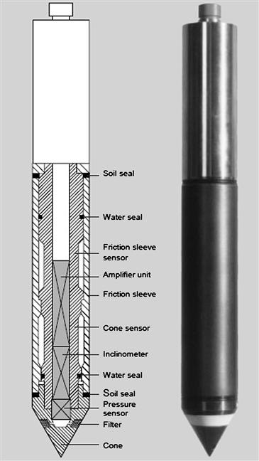
Figure 4-4 Piezocone Penetration [9]
4.4.1.3 Drilling Rig
Figure 4-5 illustrates a typical jack-up drilling rig. The drilling rig should be provided with all drill string components: the drill pipe, drill bits, insert bits, subs, crossovers, etc. The capability for the drill string on the drilling rig to be heave compensated such that the drill bit has a minimum of movement while drilling and performing downhole sampling and testing is very important.

Figure 4-5 Jack-Up Drilling Rig
Borings are drilled, using rotary techniques with a prepared drilling mud, from the seabed to the target depth. The objective of the borings is to obtain high-quality samples and perform in situ testing.
4.4.1.4 Downhole Equipment
Equipment for performing sampling and testing in downhole operation mode through a drill string is relevant to the investigation:
An ample number of cones and sample tubes should be available. Push sampling is performed with thin-wall or thick-wall sample tubes, depending on the soil conditions. The main operational requirement for downhole equipment is that the equipment be used in the maximum relevant water and drilling depths.
4.4.1.5 Laboratory Equipment
The vessel is provided with either a room or a container to act as an offshore soil testing laboratory with sufficient equipment and personnel for 24 hour per day operation. All necessary supplies and equipment for cutting liners and sealing and waxing samples, including transportation boxes for shipping of samples to the onshore laboratory, have to be carefully provided for.
The offshore laboratory varies depending on the nature of the project. Equipment is required for performing the following types of standard laboratory tests:
4.4.2 Subsea Survey Equipment Interfaces
4.4.2.1 Sound Velocity Measurement
Velocity profiles are recorded whenever necessary to ensure that the correct speed of sound in seawater is utilized for the calibrations of the geophysical and bathymetric instruments. The velocity of sound in seawater can be calculated with a recognized formula.
All equipment is operated in accordance with manufacturers’ published instructions and conforms to manufacturers’ specifications. The velocity probe and winch system are capable of operating efficiently in survey water depths. Data are to be recorded on the descent to the seabed and recovery to the surface.
The instrumentation is calibrated to the standards set by the National Bureau of Standards within the 12 months prior to the mobilization date. Calibration certificates should be included with the survey procedures.
4.4.2.2 Sediment Handling and Storage Requirements
Sediment samples are carefully marked, handled, and transported. Samples from the corer are cut in 1-m sections. The core samples are then stored in a cool place, but not frozen where shaking and shock are limited to a minimum. The sealed cylinders or waxed samples are clearly labeled with:
• A “Top Up” indicator (arrow pointing upward);
• Core location, attempt number, date, and company project number;
An identification label is placed inside the top cap.
The sealed and marked sample cylinders and waxed samples are placed in boxes suitable for transportation. If possible, the core barrels should be stored vertically. Rooms adjacent to heavy engines or generators, which generate excessive vibrations, are avoided.
The boxes with sealed sediment material are transported to the onshore laboratory with caution and handled with care. Special precautions are made to prevent shock and impact loads to the sediment material during handling of the boxes.
The sediment must not be exposed to temperatures below 0°C. Whether samples are air freighted or trucked to the onshore laboratory must be decided in each case.
Each cylinder and waxed sample is registered and stored for convenient retrieval.
On completion of the fieldwork, a sample log for each sample is prepared. The sample log includes the following information:
Whether core material is extruded on board or sealed in a tube or liner;
A short description of sediment type should be prepared based on contents in the core catcher and in each end of the liners.
4.4.2.3 Onboard Laboratory Test
The cores are cut into sections no more than 1 m in length. Disturbance of the cores is avoided during cutting and at other times. The following tests are conducted at each end of the 1-m samples:
Sediment samples obtained by the Ponar/Van Veen grab sampler are described, bagged, and sealed for transportation with the cores. A motorized miniature vane measurement is conducted within the box core sample near the center of the core where the soils are undisturbed.
4.4.2.4 Core Preparation
Prior to sealing, a visual classification of the sediment types is performed. Pocket penetrometer and shear vane tests are undertaken at the top and bottom of each core section. All cores are then labeled and sample tubes are cut to minimize air space, sealed to prevent moisture loss, and then stored vertically. Minimum labeling includes this information:
4.4.2.5 Onshore Laboratory Tests
The following tests, as applicable depending on soil types and locations, are carried out in a geotechnical laboratory on core samples sealed and undisturbed in the field as soon as possible after recovering the samples:
• UU (Un-consolidated, undrained) and triaxial (cohesive soil);
• Miniature vane (cohesive soils);
• Classification tests (Atterberg limits, water content, submerged unit weight);
The onshore laboratory program is approved prior to commencement of testing.
4.4.2.6 Near-Shore Geotechnical Investigations
To carry out geotechnical investigations in near-shore areas, a self-elevating jack-up is fully utilized or, as an alternative, an anchored barge for drilling operations in up to 20 m of water depth (WD) and as shallow as 2 m of WD.
The general requirements for certification, integrity, and safe/efficient working described in preceding sections are applied. In addition, the acceptable sanitary conditions and messing conditions are guaranteed which can reduce the impaction of environment in near-shore areas.
For support of the geotechnical drilling unit, any small boat operations should comply with the following guidelines:
• Small boats will be equipped with spare fuel, basic tool kit, essential engine spares, radar reflector, portable radio, mobile telephone, potable water, first aid kit, and distress signals/flares (secure in a water proof container).
• Small boats will only be driven by members of the crew or other personnel who have undergone a specialized small boat handling course.
4.5 Subsea Foundation
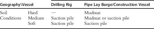
A foundation is a structure that transfers loads to the earth. Foundations are generally broken into two categories: shallow foundations and deep foundations. A subsea production structure may be supported by piles, by nudmats with skirt or directly by the seabed. It could also be supported by a combination of these three structures. Table 4-1 shows the typical foundation selection matrix.
Table 4-1. Foundation Selection Matrix
4.5.1 Pile- or Skirt-Supported Structures
The foundation piles of a pile-supported structure should be designed for compression, tension, lateral loads, and also shear stress as applicable.
The structure is properly connected to the pile/skirt (see Figure 4-6). This can be accomplished with a mechanical device or by grouting the annulus between the pile and sleeve.

Figure 4-6 Suction Pile [10]
4.5.2 Seabed-Supported Structures
The foundation of a seabed-supported structure is designed to have sufficient vertical and horizontal bearing capacity for the loads in question.
Depending on seabed conditions, high contact stresses may develop. This should be considered in the design. Underbase grouting may have to be used to achieve the required stability and load distribution on the seabed.
4.5.3 Pile and Plate Anchor Design and Installation
4.5.3.1 Basic Considerations
The technology for the evaluation of the geotechnical capacity of a suction pile and plate anchor is still under development; therefore, specific and detailed recommendations cannot be given at this point. Instead, general statements are used to indicate that consideration should be given to some particular points and references are given. Designers are encouraged to utilize all research advances available to them. It is hoped that more specific recommendations can be issued after completion of the research in this area.
4.5.4 Geotechnical Capacity of Suction Piles
4.5.4.1 Basic Considerations
Suction pile anchors resist vertical uplift loads by various mechanisms depending on the load type:
• Long-term loop current loading:
• External skin friction appropriately reduced for creep and cyclic effects due to long-term duration of the event;
• Suction piles resist horizontal loads by the following mechanisms:
The geotechnical load capacity of the anchor should be based on the lower bound soil strength properties. This is derived from the site-specific soil investigation and interpretation. Anchor adequacy with respect to installation should be based on the upper bound soil strength properties.
Because this geometry may change the relationship between the horizontal and vertical anchor loads, the impact of the mooring line geometry in the soil on the anchor loads should be considered. For example, the inverse catenary of the mooring line in the soil may make the mooring line angle steeper at the anchor. This steeper angle could result in a reduced horizontal anchor load, but an increased vertical anchor load. Both an upper and lower bound inverse catenary should be checked to ensure that the worst case anchor loading is established.
Axial safety factors take into consideration the fact that piles are primarily loaded in tension and are therefore higher than for piles loaded in compression. As with other piled foundation systems, the calculated ultimate axial soil resistance should be reduced if soil setup, which is a function of time after pile installation, will not be complete before significant loads are imposed on the anchor pile.
Because the lateral failure mode for piles is considered to be less catastrophic than vertical failure, lower factors of safety have been recommended for lateral pile capacity. Use of different safety factors for vertical and lateral pile capacities may be straightforward for simple beam-column analysis of, for example, mobile moorings, but more complex methodologies do not differentiate between vertical and lateral pile resistance. The following formula is proposed to provide a combined factor of safety for the latter situation:
![]() (4-1)
(4-1)
where
4.5.4.2 Analysis Method
It is recommended that suction pile design for permanent moorings use advanced analysis techniques such as limit equilibrium analysis or finite element analysis of the pile and adjacent soil. For example, the resultant capacity may be calculated with limit equilibrium methods, where the circular area is transformed into a rectangle of the same area and width equal to the diameter, and with 3D effects accounted for by side shear factors.
For mobile moorings, simpler beam column analysis using load transfer displacement curves (i.e., P-y, T-z, Q-z) described in API RP 2A [11] are considered adequate if suitably modified.
In areas where tropical cyclonic storms may exceed the capacity of the mobile mooring or anchoring system, such as the Gulf of Mexico, the design of suction piles should consider an anchor failure mode that reduces the chance of anchor pullout. For example, the mooring line anchor point can be located on the suction anchor such that the anchor does not tilt during soil failure, but “plows” horizontally in a vertical orientation.
4.5.5 Geotechnical Capacity of Plate Anchors
4.5.5.1 Basic Considerations
The ultimate holding capacity is usually defined as the ultimate pull-out capacity (UPC), which is the load for the soil around the anchor reaching failure mode for plate anchors. For anchors that dive with horizontal movement, the ultimate holding capacity is reached when excessive lateral drag distance has occurred. At UPC, the plate anchor starts moving through the soil in the general direction of the applied anchor load with no further increase in resistance or the resistance starts to decline. The ultimate pull-out capacity of a plate anchor is a function of the soil’s undrained shear strength at the anchor fluke, the projected area of the fluke, the fluke shape, the bearing capacity factor, and the depth of penetration. The disturbance of the soil due to the soil failure mode should be considered when analyzing the plate anchor’s ultimate pull-out capacity. This mode is generally accounted for in the form of a disturbance factor or capacity reduction factor. The bearing capacity factor and disturbance factor should be based on reliable test data, studies, and references for such anchors. The plate anchor’s penetration is usually in a range of two to five times the fluke width, depending on the undrained shear strength of the soil, in order to generate a deep failure mode. If the final depth does not generate a deep failure mode, a suitable reduction in bearing capacity factor should be used.
Plate anchors get their high holding capacity from being embedded into competent soil. Therefore, it is important for the anchor’s penetration depth to be established during the installation process. Furthermore, a plate anchor gets its high ultimate pull-out capacity by having its fluke oriented nearly perpendicular to the applied load. To ensure that the fluke will rotate to achieve a maximum projected bearing area, the plate anchor design and installation procedure should:
• Facilitate rotation of the fluke when loaded by environmental loads or during installation or both;
• Ensure that no significant or unpredicted penetration is lost during anchor rotation, which may move the fluke into weaker soil;
• Have the structural integrity to allow such fluke rotation to take place during installation and keying operations or while subject to the ultimate pull-out capacity load. Depending on the type of plate anchor and its installation orientation, this item may also apply to fluke rotation about both horizontal and vertical axes.
As appropriate, the anchor capacities should be reduced to account for anchor creep under long-term static loading and cyclic degradation.
4.5.5.2 Prediction Method for a Drag Embedded Plate Anchor
Three aspects of drag embedded plate anchor performance require prediction methods:
All three mechanisms are closely linked and influence one another, as explained next.
4.5.5.3 Prediction Method for Direct Embedded Plate Anchor
Anchor capacity determination for direct embedded plate anchors is identical to that shown for drag embedded anchors with the following exceptions:
• Final penetration depth is accurately known.
• Nominal penetration loss during keying should be included (usually taken as 0.25 to 1.0 times the fluke’s vertical dimension, or B in Figure 4-7, depending on the shank and keying flap configuration).

Figure 4-7 Special Consideration of Safety Factors for Drag Embedded Plate Anchors
• Calculation of the effective fluke area should use an appropriate shape factor and projected area of the fluke with a keying flap in its set position.
Safety factors for drag embedded plate anchors are higher because overloading of the anchor normally results in the anchor pulling out, whereas a drag anchor may drag horizontally or dig in deeper, developing constant or higher holding capacity under a similar situation. For plate anchors that exhibit overloading behaviors similar to those of drag anchors, consideration may be given to using drag anchor safety factors, assuming the behavior can be verified by significant field tests and experience.
4.5.6 Structural Design of Suction Piles
4.5.6.1 Basic Considerations
The purpose of this section is to provide guidance and criteria for the structural design of suction piles. Some of the guidance and criteria are also applicable to driven piles.
4.5.6.2 Design Conditions
The suction pile structure should be designed to withstand the maximum loads applied by the mooring line, the maximum negative pressure required for anchor embedment, the maximum internal pressure required for anchor extraction, and the maximum loads imposed on the anchor during lifting, handling, launching, lowering, and recovery. The fatigue lives of critical components and highly stressed areas of the anchor should be determined and checked against the required minimum fatigue life.
Mooring Loads on Global Anchor Structure
The load case that provides the maximum horizontal and vertical loads at the mooring padeye should be used for the global structural design of the anchor. The soil reactions generated by the geotechnical analysis will be used in these calculations. Sensitivity checks should be performed to ensure that a load case with less than the maximum load, but applied at a more onerous angle at the padeye, does not control the design.
Mooring Loads on Anchor Attachment
The mooring line attachment padeye or lug is a critical structural component. To meet fatigue resistance criteria, the padeye is often an integral cast lug and base structure. This avoids the use of heavy weldments, which can result in a lower fatigue life. The attachment padeye should be designed to satisfy both strength and fatigue requirements. The padeye should be designed for the controlling design load with an appropriate factor of safety. Designing the padeye for a maximum load equal to a factor times the break strength of the mooring line may lead to a significantly overdesigned padeye, which may not integrate well with the anchor shell and backup structures.
The mooring line padeye should be designed for the controlling load case, and sensitivity checks should be performed to ensure that a load case with less than the maximum load but applied at a more onerous angle does not control the design. The orientation of the applied load at the padeye will be affected by the inverse catenary of the mooring line, vertical misalignment due to anchor tilt, and rotational misalignment due to deviation from the target orientation. These factors should be properly accounted for.
Embedment Loads
For anchor embedment, the estimated upper bound suction pressure required to embed the anchor to its design penetration should be used for the design of the anchor wall and anchor cap structure. However, the maximum suction pressure used should not be higher than the suction at which internal plug uplift occurs.
Extraction Loads
With respect to anchor extraction, two conditions require evaluation:
• Temporary condition: Extraction of a suction pile may be required for permanent moorings. For example, after all suction piles have been preinstalled along with the mooring lines, one of the mooring lines is accidentally dropped to the seabed and damaged during the hookup operation with the vessel. At this time, a decision to extract the suction pile and recover the mooring leg may be made. Typically, such situations may occur 30 to 60 days after the first suction pile has been installed. For mobile moorings, the suction piles are often extracted at the end of the current drilling or testing operation and reused in other locations.
• Terminal condition: The suction piles for a permanent mooring may be extracted at the end of their service life. The estimated maximum internal pressure required to extract the anchor for these two situations should be used for the design of the anchor wall and anchor cap structure. However, the maximum extraction pressure used should not be higher than the pressure causing overload of soil-bearing capacity at the anchor tip. The vessel removing the anchor is often capable of applying a lifting force on the anchor with the recovery line. This assistance can significantly reduce the required extraction pressure and therefore should be included in the removal analysis.
Transportation and Handling of Loads
The suction pile structure and its installation appurtenances should be designed for the maximum loads generated during suction pile handling, transportation, lifting, upending, lowering, and recovery. The suction pile designer should interface closely with the installation contractor when determining these load cases. Design of appurtenances for these load cases is typically performed using the installation contractor’s in-house design guidelines or other recognized codes. Nevertheless, all lifting appurtenances and their supporting structures should meet the minimum requirements of API RP 2A [11].
4.5.6.3 Structural Analysis Method
Pile analysis in accordance with Section 3 of API RP 2A [11] is appropriate for piles with diameter-to-thickness ratios (D/t) of less than 120. For cylindrical piles with D/t ratios exceeding 120, it is recommended that a detailed structural finite element model be developed for the global structural anchor analysis to ensure that the anchor wall structure and appurtenances have adequate strength in highly loaded areas. Supplementary manual calculations may be appropriate for members or appurtenances subjected to local loading.
4.5.6.4 Space Frame Model
A space frame model generally consists of beam elements plus other elements needed to model specific structural characteristics. This is appropriate for piles with D/t ratios of less than 120 and for preliminary design of the top cap or padeye backup structures on large-diameter piles (i.e., D/t > 120).
Finite Element Model
Finite element analysis is recommended for the global shell structure, top cap plate and supporting members, and the padeye backup structure for piles with D/t > 120. Complex shapes such as the padeye casting or welding should also be analyzed by finite element method.
Manual Calculations
Manual calculations using empirical formulas and basic engineering principles can be performed when detailed finite element analysis is not needed.
Stress Concentration Factors
Stress concentration factors can be determined by detailed finite element analysis, physical models, and other rational methods or published formulas.
Stability Analysis
Formulas for the calculation of the buckling strength of structural elements are presented in API Recommended Practice 2A [11]; API Bulletin 2U, “Stability Design of Cylindrical Shells” [12]; and API Bulletin 2V, “Design of Flat Plate Structures” [13]. As an alternative, buckling and postbuckling analysis or model tests of specific shell or plate structures may be performed to determine buckling and ultimate strength.
Dynamic Response
Significant dynamic response is not expected for the anchor in its in-place condition; therefore, anchor structures are often analyzed statically. Transportation analysis, however, will typically include dynamic loads generated by harmonic motions of a simple single-degree-of-freedom model.
4.5.6.5 Structural Design Criteria
Design Codes
The method for structure design is the working stress design method, where stresses in all components of the structure are kept within specified values. In general, cylindrical shell elements should be designed in accordance with API RP 2A [11] for D/t ratios of less than 300 or API Bulletin 2U [8] when D/t exceeds 300, flat plate elements in accordance with API Bulletin 2V [9], and all other structural elements in accordance with API RP 2A, as applicable. In cases where the structure’s configurations or loading conditions are not specifically addressed by these codes, other accepted codes of practice can be used. In this case, the designer must ensure that the safety levels and design philosophy implied in the API Recommended Practice 2SK [14] are adequately met.
In API RP 2A, allowable stress values are expressed, in most cases, as a fraction of the yield or buckling stress. In API Bulletin 2U, allowable stress values are expressed in terms of critical buckling stresses. In API Bulletin 2V, the allowable stresses are classified in two basic limit states: ultimate limit states and serviceability limit states. Ultimate limit states are associated with the failure of the structure, whereas serviceability limit states are associated with adequacy of the design to meet its functional requirements. For the purpose of suction anchor design, only the ultimate limit state is considered.
Safety Categories
There are two safety categories: Category A safety criteria are intended for normal design conditions, and Category B safety criteria are intended for rarely occurring design conditions. The criteria listed in Table 4-2 are recommended.
Table 4-2. Suction Pile Safety Criteria [13]
| Load Condition | Safety Criteria |
| Maximum intact | A |
| Maximum one-line damaged | B |
| Anchor embedment | A |
| Anchor extraction (temporary) | A |
| Anchor extraction (terminal) | B |
| Handling/lifting/lowering/recovery | A |
| Transportation | B |
Allowable Stresses
For structural elements designed in accordance with API RP 2A [11], the allowable stresses recommended in these codes should be used for normal design conditions associated with Category A safety criteria. For extreme design conditions associated with Category B safety criteria, the allowable stresses may be increased by one-third if the working stress design method is utilized (e.g., API RP 2A-WSD [15]).
For shell structures designed in accordance with API Bulletin 2U [12], a factor of safety equal to 1.67Ψ is recommended for buckling modes for Category A safety criteria. For Category B safety criteria, the corresponding factor of safety is equal to 1.25Ψ. The parameter Ψ varies with buckling stress and is defined in API Bulletin 2U. It is equal to 1.2 for elastic buckling stresses at the proportional limit and reduces linearly for inelastic buckling to 1.0 when the buckling stress is equal to the yield stress.
For flat plate structures designed in accordance with API Bulletin 2V [13], the allowable stress is obtained by dividing the ultimate limit state stress by an appropriate factor of safety, which is 2.0 for Category A safety criteria and 1.5 for Category B safety criteria.
For cylindrical elements with D/t ratios exceeding 120, it is recommended that global strength be analyzed using finite element techniques. Local buckling formulations for axial compression, bending, and hydrostatic pressure given in API RP 2A [11] for D/t <300 and API Bulletin 2U [12] D/t ≥ 300 are considered valid if due consideration is made for variable wall thicknesses (when it occurs) and buckling length (which may extend below the mudline when performing suction embedment analysis).
The nominal Von Mises (equivalent) stress at the element’s extreme fiber should not exceed the maximum permissible stress as calculated below:
![]() (4-2)
(4-2)
where
Design factors for the listed load conditions are given in Table 4-3.
Table 4-3. Design Factors for Finite Element Analysis
| Load Condition | Design Factor ηi |
| Maximum intact | 0.67 |
| Maximum one-line damaged | 0.90 |
| Anchor embedment | 0.67 |
| Anchor extraction (temporary) | 0.67 |
| Anchor extraction (terminal) | 0.90 |
| Handling/lifting/lowering/recovery | 0.67 |
| Transportation | 0.90 |
4.5.7 Installation of Suction Piles, Suction Caissons, and Plate Anchors
4.5.7.1 Suction Piles and Suction Caissons
Installation Procedure, Analysis, and Monitoring
Installation procedures should be developed and installation analyses should be performed for suction pile and suction caisson anchors to verify that the anchors can penetrate to the design depth. The installation analysis should also consider anchor retrieval for the following cases:
• Mobile moorings where anchor removal is needed for reuse of the anchor or to clear the seabed. The suction pile retrieval procedures and analysis should account for the estimated maximum setup time.
• Permanent moorings where it is required by authorities that the anchors be removed after the system service life. The suction pile retrieval procedures and analysis should be based on full soil consolidation.
For suction pile embedment analysis, the risk of causing uplift of the soil plug inside the anchor should be considered. The allowable underpressure to avoid uplift should exceed the required embedment pressure by a factor of 1.5.
Anchor installation tolerances should be established and considered in the suction pile anchor geotechnical, structural, and installation design process. The following typical tolerances should be considered:
• Allowable anchor tilt angle in degrees;
• Allowable deviation from target orientation of the mooring line attachment to limit padeye side loads and rotational moments on the anchor;
• Minimum penetration required to achieve the required holding capacity.
Suction pile installation analysis should provide the relevant data needed for the suction pile design and installation procedures. The following typical information is required:
• Anchor self-weight penetration for applicable soil properties or range of properties;
• Embedment pressure versus penetration depth for applicable soil properties;
To verify that the suction pile installation is successful and in agreement with the design assumptions, the following data should be monitored and recorded during the installation of suction piles:
• Embedment pressure versus penetration depth;
• Internal plug heave (by direct or indirect means);
For the installation of temporary mooring suction pile anchors, measurement of the internal plug heave is not required if the anchor reaches its design embedment depth.
Skirt Penetration of Suction Caissons
The following points should be given attention when designing the skirt penetration capability of suction caissons:
• The skirt penetration resistance should account for the reduced shear strength along the skirt wall due to the disturbance during penetration. Normally, the remolded shear strength is applied.
• Stiffeners (outside and inside) may influence the penetration resistance, because additional force may be required to penetrate them, and the failure mode around internal stiffeners should be given attention. On the other hand, a gap may form above outside and inside stiffeners. This may reduce the penetration resistance and form potential flow paths. In the case of several ring stiffeners, clay from the upper part of the profile may be trapped between the stiffeners and give low resistance at larger depth. In stiff clays the soil plug may stand open, giving essentially no skin friction along the inside wall.
• The allowable underpressure for penetration should be calculated as the sum of the inverse bearing capacity at skirt tip and the internal skirt wall friction. There is some controversy as to whether the conventional bearing capacity factor can be used to calculate the end bearing capacity below the skirt tip, but most designers tend to assume conventional bearing capacity factors.
• If the outside or inside suction caisson skirt wall is given surface treatment (e.g., painting), this may cause reduction in the skirt wall friction, which should be taken into account in the calculations.
4.5.7.2 Plate Anchors
Direct Embedded Plate Anchors
Direct embedment of plate anchors can be achieved by suction, impact or vibratory hammer, propellant, or hydraulic ram. The suction embedded plate anchor (SEPLA) has been used for major offshore mooring operations. As an example, the SEPLA uses a so-called suction follower, which is essentially a reusable suction anchor with its tip slotted for insertion of a plate anchor. The suction follower is immediately retracted by reversing the pumping action once the plate anchor is brought to the design depth, and can be used to install additional plate anchors. In the SEPLA concept, the plate anchor’s fluke is embedded in the vertical position and necessary fluke rotation is achieved during a keying process by pulling on the mooring line.
Installation procedures should be developed and installation analyses should be performed for direct embedded plate anchors to verify that the anchors can penetrate to the design depth. The installation analysis should also consider plate anchor retrieval if applicable.
For the embedment analysis, the risk of causing uplift of the soil plug inside the suction embedment tool should be considered. The allowable underpressure to avoid uplift should exceed the required embedment pressure by a factor of 1.5.
Plate anchor installation tolerances should be established and considered in the anchor’s geotechnical, structural, and installation design process. The following typical tolerances should be considered:
• Allowable deviation from target heading of the mooring line attachment to limit padeye side loads and rotational moments on the anchor padeye;
• Minimum penetration required before keying or test loading to achieve the required holding capacity;
• Allowable loss of anchor penetration during plate anchor keying or test loading.
Suction embedment analysis should provide relevant data needed for the design and installation procedures, which should allow verification of the assumptions used in the anchor design. The following typical information is required:
• Suction embedment tool self-weight penetration for applicable soil properties or range of properties;
• Embedment pressure versus penetration depth for applicable soil properties;
To verify that the plate installation is successful and in agreement with the assumptions in design, the following data should be monitored and recorded during the installation of the suction embedment tool to verify the assumption used in design:
Drag Embedded Plate Anchors
For drag embedded plate anchors used in permanent moorings, the installation process should provide adequate information to ensure that the anchor reaches the target penetration, and that the drag embedment loads are within the expected load range for the design soil conditions. The following typical information should be monitored and verified:
4.5.7.3 Test Loading of Anchors
For suction piles, suction caissons, and plate anchors, the installation records should demonstrate that the anchor penetration is within the range of upper and lower bound penetration predictions developed during the anchor geotechnical design. In addition, the installation records should confirm the installation behavior, that is, self-weight penetration, embedment pressures, and drag embedment loads and that the anchor orientation is consistent with the anchor design analysis. Under these conditions, test loading of the anchor to a full intact storm load should not be required.
Plate anchors should be subjected to adequate keying loads to ensure that sufficient anchor fluke rotation will take place without further loss of anchor penetration. The keying load required and amount of estimated fluke rotation should be based on reliable geotechnical analysis and verified by prototype or scale model testing. The keying analysis used to establish the keying load should also include analysis of the anchor’s rotation when subjected to the maximum intact and one-line damage survival loads. If the calculated anchor rotation during keying differs from the anchor rotation in survival conditions, then the anchor’s structure should be designed for any resulting out-of-line loading to ensure that the anchor’s structural integrity is not compromised.
In cases where the installation records show significant deviation from the predicted values and these deviations indicate that the anchor holding capacity may be compromised, test loading of the anchor to the maximum dynamic intact load may be required and may be an acceptable option to prove holding capacity for temporary moorings. However, testing anchors to the maximum intact load does not necessarily prove that required anchor holding safety factors have been met, which is of special concern for permanent mooring systems. Consequently, if the installation records show that the anchor holding capacity is significantly smaller than calculated and factors of safety are not met, then other measures to ensure adequate factors of safety should be considered:
• Additional soil investigation at the anchor location to establish and/or confirm soil properties at the anchor site;
• Retrieval of the anchor and reinstallation at a new undisturbed location;
• Retrieval of the anchor, redesign and reconstruction of the anchor to meet design requirements, and reinstallation at a new undisturbed location;
• Delay of vessel hookup to provide additional soil consolidation.
4.5.8 Driven Pile Anchor
4.5.8.1 Basic Considerations
Driven pile anchors provide a large vertical load capacity for taut catenary mooring systems. The design of driven pile anchors builds on a strong industry background in the evaluation of geotechnical properties and the axial and lateral capacity prediction for driven piles. The calculation of driven pile capacities, as developed for fixed offshore structures, is well documented in API RP 2A. The recommended criteria in API RP 2A should be applied for the design of driven anchor piles, but with some modifications to reflect the differences between mooring anchor piles and fixed platform piles.
The design of a driven pile anchor should consider four potential failure modes:
1. Pull-out due to axial load;
2. Overstress of the pile and padeye due to lateral bending;
The safety factors of holding capacity is defined as the calculated soil resistance divided by the maximum anchor load from dynamic analysis.
4.5.8.2 Geotechnical and Structural Strength Design
In most anchor pile designs, the mooring line is attached to the pile below the seafloor, to transfer lateral load to stronger soil layers. As a result, the design should consider the mooring line angle at the padeye connection resulting from the “reverse catenary” through the upper soil layers. Calculation of the soil resistance above the padeye location should also consider remolding effects due to this trenching of the mooring line through the upper soil layers.
Driven pile anchors in soft clay typically have aspect ratios (penetration/diameter) of 25 to 30. Piles having such an aspect ratio would be fixed in position about the pile tip and consequently would deflect laterally and fail in bending before translating laterally as a unit. Driven pile anchors are typically analyzed using a beam-column method with a lateral load-deflection model (p-y curves) for the soil. These computations should include the axial loading in the pile, as well as the mooring line attachment point, which will influence the deflection, shear, and bending moment profiles along the pile. Pile stresses should be limited to the basic allowable values in API RP 2A [11] under intact conditions. Basic allowable stresses may be increased by one-third for rarely occurring design conditions such as a one-line damaged condition.
Because an anchor pile near its ultimate holding capacity experiencing the largest deflection always engages new soil, “static” p-y curves may be considered for calculation of lateral soil resistance. “Cyclic” p-y curves may be more appropriate for fatigue calculations, because the soil close to the pile will be more continually disturbed due to smaller, cyclic deflections. The p-y curve modifications developed by Stevens and Audibert [16] are recommended in place of the API RP 2A p-y curves, to obtain more realistic deflections. Consideration should be given to degrading the p-y curves for deflections greater than 10% of the pile diameter. In addition, when lateral deflections associated with cyclic loads at or near the mudline are relatively large (e.g., exceeding yc as defined in API RP 2A for soft clay), consideration should be given to reducing or neglecting the soil-pile adhesion (skin friction) through this zone.
The design of driven anchor piles should consider typical installation tolerances, which may affect the calculated soil resistance and the pile structure. Pile verticality affects the angle of the mooring line at the padeye, which changes the components of the horizontal and vertical mooring line loads that the pile must resist. Underdrive will affect the axial pile capacity and may result in higher bending stresses in the pile. Padeye orientation (azimuth) may affect the local stresses in the padeye and connecting shackle. Horizontal positioning may affect the mooring scope and/or angle at the vessel fair lead, and should be considered when balancing mooring line pretensions.
4.5.8.3 Fatigue Design
Basic Considerations
Anchor piles should be checked for fatigue caused by in-place mooring line loads. Fatigue damage due to pile driving stresses should also be calculated and combined with in-place fatigue damage. For typical mooring systems, fatigue damage due to pile driving is much higher than that caused by in-place mooring line loads.
In-Place Loading
A global pile response analysis accounting for the pile–soil interaction should be carried out for the mooring line reactions due to the fatigue sea states acting on the system. The local stresses that accumulate fatigue damage in the pile should be obtained by calculating a stress concentration factor (SCF), relative to the nominal stresses generated by the global analysis, at the fatigue critical locations. These locations are typically at the padeye, at the girth welds between the padeye and the pile, and between subsequent pile cans.
The evaluation of SCFs for girth welds needs to account for the local thickness misalignment at the weld. Note that the calculated SCF needs to be corrected by the ratio of the nominal thickness used in the pile response analysis to the lesser of the pile wall thicknesses joining at the weld. The SCF is to be applied to the nominal pile stress range obtained at the weld location due to in-place loads, from which damage is to be calculated.
Installation Loading
Dynamic loads due to hammer impact during pile installation will induce fatigue damage on both padeye and pile girth welds. The evaluation of the cyclic loads involves the dynamic response of the pile–soil system due to the hammer impact. This requires a wave equation analysis per blow for a given hammer type and efficiency, pile penetration, and soil resistance. Various such analyses are to be conducted for judiciously selected pile penetrations. For each analysis, traces of stress versus time at the critical locations along the pile are to be developed, as well as the number of blows associated with the assumed penetration.
For either welds or padeye, fatigue load calculations should be carried out at various pile locations using local stress range, derived from the wave equation analysis at the selected pile penetrations. The location of the girth weld should be determined by the pile makeup schedule. The local response should include the corresponding SCF effect. The number of cycles of the stress history per blow is obtained using a variable amplitude counting method, such as the reservoir methods.
Fatigue Resistance
Applicable SN curves (stress-number of cycles to failure) depend on the manufacturing processes and defect acceptance criteria. Typically, pile sections are welded by a two-sided SAW (Submerged Arc Welding) process and are left in the as-welded condition. For this case, the D curve may be used. Use of a higher SN curve for this application, without additional treatment of the weld, should be demonstrated by relevant data. Use of weld treatment methods, such as grinding, may support the upgrading of the SN curve, provided that (1) the grinding process is properly implemented, (2) weld inspection methods and defect acceptance criteria are implemented, and (3) pertinent fatigue data are generated to qualify the weld to a performance level higher than that implied by the D curve.
Total Fatigue Damage and Factor of Safety
Once the fatigue loading and resistance have been determined, fatigue damage due to in-place and installation loads can be evaluated. The total fatigue damage should satisfy the following equation for the critical structural elements:
![]() (4-3)
(4-3)
where D1 is calculated fatigue damage for phase 1, that is, the installation (pile driving) phase and transportation phase, if significant. The D2 term is the calculated fatigue damage for phase 2, that is, the in-service phase, during the service life (e.g., 20 years). The factor of safety is F and is equal to 3.0.
4.5.8.4 Test Loading of Driven Pile Anchors
The driven pile installation records should demonstrate that the pile self-weight penetration, pile orientation, driving records, and final penetration are within the ranges established during pile design and pile driving analysis. Under these circumstances, test loading of the anchor to full intact storm load should not be required. However, the mooring and anchor design should define a minimum acceptable level of test loading. This test loading should ensure that the mooring line’s inverse catenary is sufficiently formed to prevent unacceptable mooring line slacking due to additional inverse catenary cut-in during storm conditions. Another function of the test loading is to detect severe damage to the mooring components during installation.
REFERENCES
1. GEMS, Vessel Specification of MV Kommandor Jack, <www.gems-group.com>.
2. K.F. Anschütz, Cutaway of Anschütz Gyrocompass, <http://en.wikipedia.org/wiki/Gyrocompass>.
3. Navis.gr, Gyrocompass - Steaming Error http://www.navis.gr/navaids/gyro.htm.
4. House DJ. Seamanship Techniques: Shipboard and Marine Operations. Butterworth-Heinemann 2004.
5. Mayer L, Li Y, Melvin G. 3D Visualization for Pelagic Fisheries Research and Assessment, ICES. Journal of Marine Science. 2002;vol. 59.
6. Isaev BM. Measurement Techniques, vol 18, No 4. Plenum Publishing Co 2007.
7. Milne PH. Underwater Acoustic Positioning Systems. Houston: Gulf Publishing; 1983.
8. Christ RD, Wernli RL. The ROV Manual, Advantages and Disadvantages of Positioning Systems. Butterworth-Heinemann 2007.
9. Fugro Engineers B.V., Specification of Piezo-Cone Penetrometer, <http://www.fugro-singapore.com.sg>.
10. Faulk M. FMC ManTIS (Manifolds & Tie-in Systems). Houston: SUT Subsea Awareness Course; 2008.
11. American Petroleum Institute. Recommended Practice for Planning, Designing and Constructing Fixed Offshore Platforms - Load and Resistance Factor Design. API RP 2A-LRFD 1993.
12. American Petroleum Institute. Bulletin on Stability Design of Cylindrical Shells. API Bulletin 2U 2003.
13. American Petroleum Institute. Design of Flat Plate Structures. API Bulletin 2V 2003.
14. American Petroleum Institute. Design and Analysis of Station Keeping Systems for Floating Structures. API RP 2SK 2005.
15. American Petroleum Institute, Recommended Practice for Planning, Designing and Constructing Fixed Offshore Platforms - Working Stress Design - Includes Supplement 2, API 2A WSD, 2000.
16. Stevens JB, Audibert JME. Re-Examination of P-Y Curve Formulations. Houston: OTC 3402; 1979.