
Design and Study on Intelligent Controller
Abstract
The intelligent vibration control strategies are applied to real structures through the intelligent controller, thus the hardware design of the intelligent controller is very important to the effectiveness of intelligent control of civil engineering structures. In this chapter, the intelligent controller of magnetorheological dampers is taken for example to introduce the hardware design method of intelligent controllers, and then experimental study is carried out to verify the effectiveness of the intelligent controllers.
Keywords
Intelligent controller; MR damper; experimental study
In Chapter 2, Intelligent Control Strategies, different kinds of control strategies for intelligent vibration control are described. These control strategies are applied to the real structures by an intelligent controller in real time. In this chapter, the hardware design and experimental study for intelligent controller will be introduced. Taking the intelligent controller as an example, in 2004, Lord Corporation and Motorola Incorporation et al. [238] designed controllers of magnetorheological (MR) dampers in the automobile field. In 2007, Liu [239] presented a controllable current amplifier for MR damper. In 2012, Guo et al. [240] developed a single-chip microprocessor for MR damper coupling sensing and control.
The controller should include two parts: the sensing system and the control system. That is, the controller can collect status signals of the structures, and at the same time it can produce control signals of MR dampers according to status signals.
6.1 Design of Intelligent Controller
An intelligent controller for MR dampers coupling sensing and control functions is designed in accordance with the following principles: (1) the sensors collect the responses of the controlled structure and transmit them to the microcontroller in real time, which can be acceleration responses, displacement responses, velocity responses or stress responses, and so on; (2) the control current signals of MR dampers are calculated based on the collected responses of the controlled structure by microcontroller in which the control strategies are written in advance; (3) the control currents are applied to MR dampers through the pulse-width modulation (PWM) technology, and then MR dampers will produce different damping force according to different control currents to mitigate the structural vibration responses, as shown in Fig. 6.1. In the following section, the design method of the controller based on structural acceleration responses will be introduced in detail.

6.1.1 The Design of the Acceleration Responses Collection
In the process of the vibration mitigation control of structures with MR dampers, the structural acceleration response is usually considered as one of the most important parameters, which will clearly show the vibration condition of the structure, and it is also very useful to determine control currents of MR dampers, so the real-time acceleration responses of the controlled structure are adopted as the input of the control system. A three axes low-g micromachined accelerometer, MMA7260QT (as shown in Fig. 6.2), is used to collect the real-time acceleration responses of the structure.

The MMA7260QT [241] is a low-cost capacitive micromachined accelerometer. It features signal conditioning, a one-pole low-pass filter, temperature compensation, and g-Select, which allows for the selection among four sensitivities. Zero-g offset full scale span and filter cut-off are factory set and require no external devices. It includes a Sleep Mode that makes it ideal for handheld battery powered electronics. The device can measure both positive and negative accelerations, and transform acceleration of the voltage signal. With no input acceleration, the output is at mid-supply. For positive acceleration, the output will increase above VDD/2 (VDD is the supply voltage). For negative acceleration, the output will decrease below VDD/2. So the relationship between the acceleration input and the voltage output of the MMA7260QT is
(6.1)
where ![]() is the acceleration input and
is the acceleration input and ![]() is the voltage output. In this paper, according to the MMA7260QT’s features, it is used to collect the three-way acceleration responses of the structure in real-time, and then the voltage output signal will be sent to the microcontroller. Fig. 6.3 shows the connection diagram of MMA7260QT.
is the voltage output. In this paper, according to the MMA7260QT’s features, it is used to collect the three-way acceleration responses of the structure in real-time, and then the voltage output signal will be sent to the microcontroller. Fig. 6.3 shows the connection diagram of MMA7260QT.

6.1.2 The Design of the Microcontroller
The microcontroller chip is the core component of the MR damper intelligent controller. Its main function is to generate the control current signal of the MR damper based on the real-time vibration acceleration responses of the controlled system collected by the acceleration sensor. A eight-bit ATmega16 microcontroller is used to generate the control current signal to the MR dampers by using the PWM technology.
6.1.2.1 The PWM technology
In the process of controlling the MR dampers, the control currents of MR dampers will change from 0 to 3 A, but usually the circuit board only can withstand the maximum current of 1 A, that is, the controller cannot provide currents to MR dampers directly. In order to solve this problem, the PWM technology is used to control the power source and realize the control current supply of MR dampers.
The PWM technology [242] is a powerful technique for controlling analog circuits with digital outputs of a processor. The PWM technology is employed in a wide variety of applications, ranging from measurement and communications to power control and conversion. As known, at any moment, the output of the digital circuit only has two states, ON and OFF. On the other hand, an analog signal has a continuously varying value, with infinite resolution in both time and magnitude. The PWM technology is a way of digitally encoding analog signal levels. Through the use of high-resolution counters, the duty cycle of a square wave is modulated to encode a specific analog signal level. The PWM signal is still digital because, at any given instant of time, the full Direct Current (DC) supply is either fully on or fully off. The voltage or current source is supplied to the analog load by means of a repeating series of ON and OFF pulses. The ON-time is the time during which the DC supply is applied to the load, and the OFF-time is the period during which the supply is switched off. Given a sufficient bandwidth, any analog value can be encoded with PWM. At the same time, one of the advantages of PWM is that the signal remains digital all the way from the processor in the controlled system; no digital-to-analog conversion is necessary. By keeping the digital signal, noise effects are minimized.
6.1.2.2 The microcontroller chip
The microcontroller, ATmega16 [243], produced by Atmel Corporation, is a high-performance, low-power eight-bit microcontroller. Fig. 6.4 shows its top view and pin connections. The ATmega16 is a low-power CMOS eight-bit microcontroller based on the AVR-enhanced Reduced Instruction Set Computer (RISC) architecture. By executing powerful instructions in a single clock cycle, the ATmega16 achieves throughputs approaching 1 Million Instructions Per Second (MIPS) per MHz allowing the system designer to optimize power consumption versus processing speed. The ATmega16 has 32 Programmable I/O Lines and 4 PWM channels, so it can perform these three kinds of tasks, which are the acceleration processing, the control instructions calculating, and the PWM signal generating.

Fig. 6.5 is the connection diagram of ATmega16. It can be seen from Figs. 6.3 and 6.5 that: (1) The ATmega16’s PB0 and PB1 pins are connected with the MMA7260QT’s g-select1 and g-select2 pins, respectively, to set up the sensor’s working rage; (2) The ATmega16’s PB2 pin is connected to the MMA7260QT’s sleepmode pin to set up the sensor’s sleep mode; (3) The ATmega16’s PA0, PA1, and PA2 pins of are connected with the MMA7260QT’s Xout, Yout, and Zout pins, respectively, to receive the different direction, acceleration data of the structure collected by the sensor. After the ATmega16 received the acceleration of data structure, it will calculate the control currents of the MR damper according to the control algorithm written in the ATmega16 in advance, and then the decided currents will be outputted to the optical coupler through the ATmega16’s PWM pin (the ATmega16’s PD4 pin).

6.1.2.3 The optical coupler
Due to the circuit cannot support the large load voltage, an optical coupler is used to protect the controller from burning out. Optical coupler is a semiconductor device, which is designed to transfer electrical signals by using light waves in order to provide coupling with electrical isolation between circuits or systems. The main purpose of an optical coupler is to prevent rapidly changing voltages or high voltages on one side of a circuit from distorting transmissions or damaging components on the other side of the circuit, and to separate the high-voltage side from the low-voltage side.
In this chapter, the optical coupler, SFH618A, is used. It features a high-current-transfer ratio, low-coupling capacitance, and high-isolation voltage. Fig. 6.6 is the connection diagram of SFH618A.

6.2 Experimental Study on Intelligent Controller
According to the above design principle, the intelligent controller is developed, as shown in Fig. 6.7. In order to grasp and analyze the performance of the intelligent controller, a series of experiments are carried out, including static experiment and dynamic experiment, as shown in Fig. 6.8. In the process of the static experiment, the controller is connected to the MR damper, and they are motionless, so the acceleration and the PWM signal are constant. The PWM signal is shown on the oscilloscope, as shown in Fig. 6.8. During the dynamic experiment, the controller is fixed on the top of the actuator of a fatigue testing machine, and it will vibrate with the actuator under the different sine wave excitations. The PWM signal output of the controller and values of the magnetic field intensity produced by the MR damper will be shown on the oscilloscope and the tesla meter in real time, respectively.

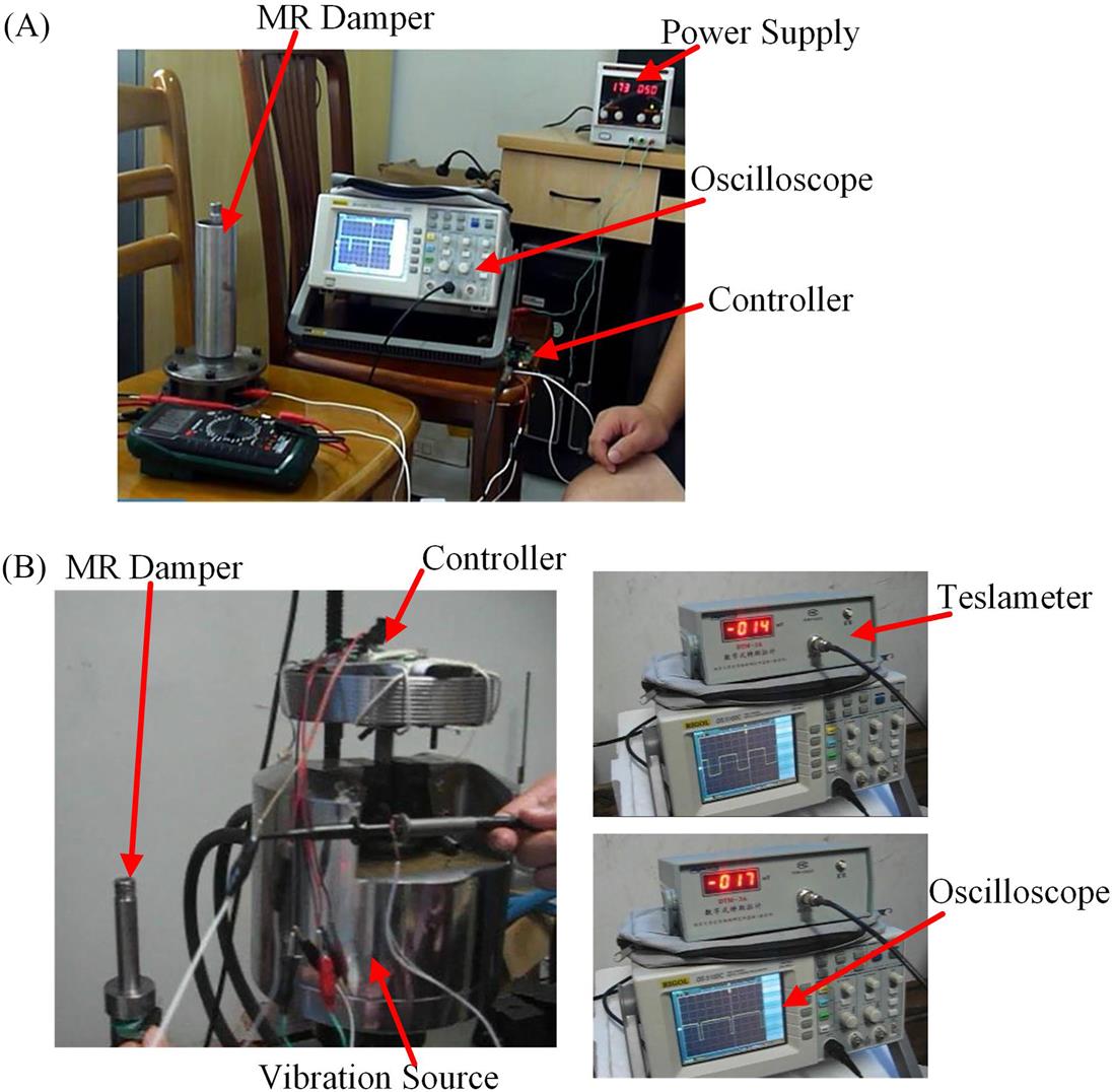
Fig. 6.9 shows the comparison between experimental and numerical results of current of the MR damper under different acceleration excitations. It can be seen that the experimental value is 1.032 A, the numerical value is 1.000 A, and the maximum relative error between the experimental and numerical results of current is 3.2% when the acceleration excitation is 0.98 m/s2. That is, the experimental and numerical results are consistent, and the controller can produce the control currents of the MR dampers in real time in accordance with the measured acceleration data.
