Text, Mtext, Editing, and Style
Learning Objectives
Text allows your design to communicate beyond the level of just a line drawing can. In this chapter, we introduce text, mtext, style, and editing and discuss the following topics:
At the end of this chapter you will be able to annotate your floor plan as well as add additional features, such as furniture and stairs.
Estimated time for completion of chapter: 2 hours (lesson and project).
4.1 Introduction to Text and Mtext
Adding text to your AutoCAD drawing is the next logical step once you learn how to create and edit basic designs. After all, the purpose of most drawings is to describe how to build something or show what a design looks like. Text goes a long way in assisting in this and, along with dimensions, is usually the next item to be added to a new design.
Text in AutoCAD comes in two versions: regular text (single line text) and mtext (multiline text). There are some overlaps and similarities between the two, and we look at how to create and edit both types. We then look at how to choose and set fonts and conclude the chapter by adding text to the previously designed floor plan.
4.2 Text
This is your basic text creation command, and it creates a field anywhere you click on the screen, into which you can type whatever text you need. It does have a carriage return that goes to another line upon pressing Enter, so you need to press Enter twice to get out of the field. While an unlimited number of lines of text can be typed, typically regular text is used for only a single line, as multiple lines of text are not joined together in paragraph form and cannot be formatted to any significant extent. Let us summarize:
![]() Text is used mostly when only one or a few lines are needed.
Text is used mostly when only one or a few lines are needed.
![]() The text cannot be formatted nor any effects added, beyond underlining and a few other minor effects.
The text cannot be formatted nor any effects added, beyond underlining and a few other minor effects.
![]() Multiple lines of text are not in paragraph form, rather they remain individual lines.
Multiple lines of text are not in paragraph form, rather they remain individual lines.
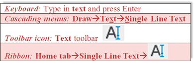
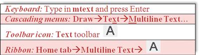
Open a new file, bring up the Text toolbar (Figure 4.1), and let us create a few sample lines.
Step 1. Begin the text command via any of the previous methods.
Current text style: "Standard" Text height: 0.2000
Specify start point of text or [Justify/Style]:
Step 2. Left-click anywhere on the screen.
![]() AutoCAD says: Specify height<0.2000>:
AutoCAD says: Specify height<0.2000>:
Step 3. Enter a new height if desired, say 1.0, and press Enter.
![]() AutoCAD says: Specify rotation angle of text<0>:. You can rotate the text, but there really is no need to, so just type in 0 for now, and press Enter.
AutoCAD says: Specify rotation angle of text<0>:. You can rotate the text, but there really is no need to, so just type in 0 for now, and press Enter.
Step 4. A text field opens up with a blinking cursor. Go ahead and type something, pressing Enter once to go to the next line or twice to finish. Figure 4.2 shows what the basic text looks like. If yours is a different size, you may have to zoom in or out to fit it nicely on the screen.
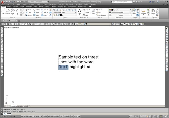
The text is still rather simple; we have not yet addressed font, sizing, or any effects. Notice that the text is on three separate lines. You can move, copy, or erase any of the two lines without affecting the other. So how would you edit this text?
Editing Text
Editing, or changing, what the text says is very simple and follows the same procedure for both text and mtext, so we go over it right away for both cases. The easiest way to edit the text is to double-click on it, which opens the text field. This is such an overriding and best method, preferred by most students, that in this particular case you do not see a command matrix detailing the other methods (a toolbar icon does exist for this). However, it is worth noting an older typed equivalent of the double-click called ddedit. If you type that in, press Enter, and click on the text, you can edit it. This method is rarely used; however, remember ddedit for Chapter 6. It is the only way to change dimension text values, so you will need it eventually, just not yet. Whichever method you use, when you are done editing, just press Enter again. Do not press Esc, as that cancels whatever editing you just did.
Here is a trick with regular text that you will not hear about much anymore. If you want to underline it, type in %%u just before the text string you want underlined. This old code dates back to DOS days, and it will automatically and immediately add an underline to your basic text. You can also experiment with %%c, %%p, and %%d. See what those three do. None of this is needed with mtext, as discussed next.
4.3 Mtext
Mtext is short for multiline text. In other words, this is the command you use when you anticipate typing in a paragraph as opposed to one or two lines, and more importantly when you require some advanced formatting and effects. As in AutoCAD 2010, it even has a spell checker built in. Many designers use mtext for all their text needs, just in case formatting needs to be applied to even just one word. The only downsides are that it takes a few seconds longer to set up and the features make it a more complex command. The idea here is to define an area where your text will go. Once you do that, the new paragraph fits into that area.
Let us summarize the mtext features and try the command:
![]() Used primarily for writing paragraphs.
Used primarily for writing paragraphs.
![]() Has extensive formatting and editing features.
Has extensive formatting and editing features.
Step 1. Begin the mtext command via any of the previous methods.
Current text style: “Standard” Text height: 0.2000
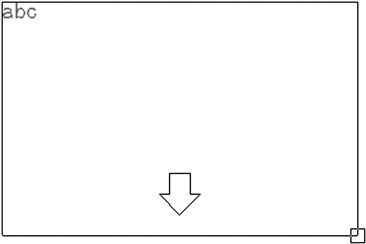
Step 2. Left-click anywhere on the screen, noticing the abc next to the crosshairs. A rectangle with an arrow appears, as shown in Figure 4.3. Continue to move your mouse down and across to the right, making the rectangle bigger. This is your text field; make it as large or small as you need it to be to hold all the text. As you do this,
![]() AutoCAD says: Specify opposite corner or [Height/Justify/Line spacing/Rotation/Style/Width/Columns]:
AutoCAD says: Specify opposite corner or [Height/Justify/Line spacing/Rotation/Style/Width/Columns]:
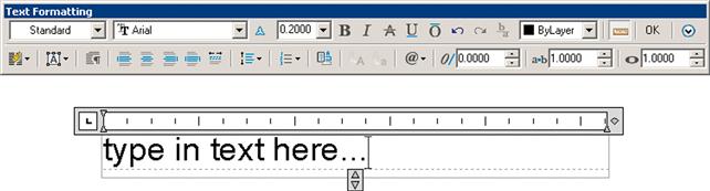
Here, AutoCAD throws you a bit of a twist. If you are not using the Ribbon, you will see the text field with a toolset just above it (but not attached to it), as seen in Figure 4.4, where you can type in your text, pressing Enter to go to the next line. To finish up, press OK in the upper right of the toolset or just click anywhere outside the field. We go over some of the tools in a moment, but what if you have the Ribbon up?
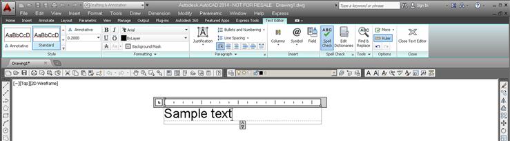
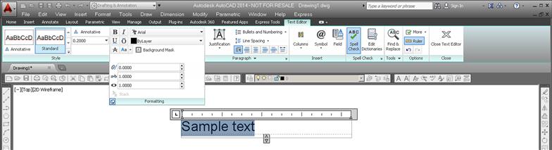
If you are using the Ribbon, the formatting duties are transferred completely to the Text Editor tab, and all you see below it is the text field, no toolset, as seen in Figure 4.5 (although you can bring it back, via the Text Editor’s Options category). The functionality is essentially the same, only the presentation differs. We cover mtext’s extensive formatting tools in the next section.
Formatting Mtext
First of all, notice something: If you click on mtext, it remains a paragraph, a big difference from a few lines of regular text. To edit mtext, as already mentioned, you do the same thing as for regular text, that is, double-click on it, use the icon, or type in ddedit. Now, on to formatting. Mtext has a lot of additional features, and once you input the text, you can modify it significantly. Some intent was made here to mimic MS Word’s text editing abilities, and although AutoCAD cannot really come close to a dedicated word-processing program, the available tools are still quite extensive. We take a look at the non-Ribbon toolset first and cover the tools again, this time using the Ribbon’s Text Editor (in much less detail, as the tools essentially are the same).
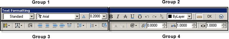
Looking at the Text Formatting toolbar from left to right, as shown in Figure 4.6, we have the following groups:
Group 1. This is where you set name, font, and size, although this is generally done using style, to be discussed later. You can also make the text annotative, to be covered in Level 2.
Group 2. These are the standard Bold, Italic, Strikeout, Underline, Overline, and Undo/Redo buttons. This is also where you set color, although that is usually done by layer. The Ruler icon turns off the ruler grid; the OK button closes the field; and the down arrow brings up additional options, to be covered soon.
Group 3. Here you find a tool for making columns and some of the associated settings, paragraph justification tools, as well as tools to change line spacing, numbering, and fields.
Group 4. Here you find tools to change from upper to lower case (and vice versa), symbols (to be discussed soon), oblique, width factor, and tracking tools.
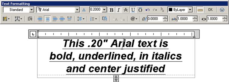
You may be familiar with most of these if you ever typed a document in MS Word. Just as in Word, you need to highlight the text to which you want the changes to apply. Experiment with the buttons to see what they all do, and try to duplicate what you see in Figure 4.7. Notice also how Arial is the default font in AutoCAD.
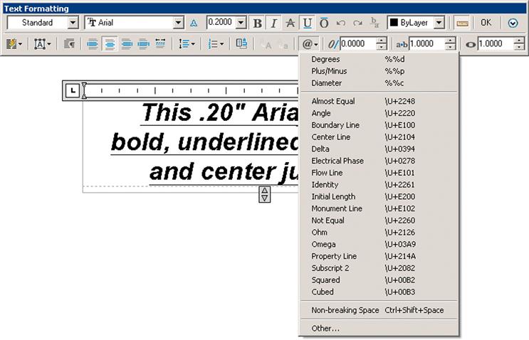
There is more to the mtext command than just the main toolbar detailed in Figure 4.6, although it does contain most of the often used commands. Two additional menus are accessed by either right-clicking while inside the mtext box or pressing the @ symbol icon in Group 4. We cover this @ menu first; it introduces a vast array of available symbols.
Figure 4.8 shows what this menu looks like. Examine it closely; it has interesting and useful options. In architecture and engineering, one typically encounters many industry- or trade-specific symbols. AutoCAD provides a significant database of them for your use. Browse through and try a few by clicking and making them appear in your text field.
In case none of those symbols is what you are looking for, there are more. At the bottom of the menu, click on Other…. A character map appears, as shown in Figure 4.9.
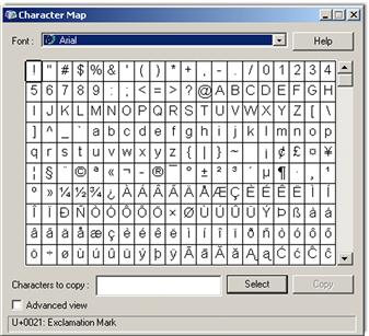
It is similar to the character map used by MS Word and functions the same way. This is basically a database of available letters (in English and several other languages) as well as symbols and characters. The choices change somewhat from font to font. To use this tool, simply click on a symbol you want (it will temporarily increase in size so you can examine it closer), and press the Select button. Then, minimize the Character Map box (or close it if you do not need it anymore), and right-click to paste back into your mtext field.
Character maps are generally for symbols not found in the main list of the drop-down table (Figure 4.8). If you see the symbol you want there first, use it. To introduce the final menu, right-click in the mtext field and you see the menu in Figure 4.10.
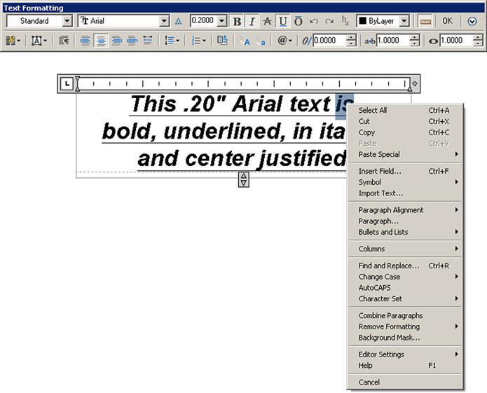
Some of these menu choices duplicate what is already seen in the main mtext menu bar, and you can access all the symbols through here as well. Aside from some Cut and Paste choices, this menu just presents an alternate way of making option selections.
As mentioned before, Ribbon users are presented with essentially the same formatting tools but in a rearranged manner. Figure 4.11 is the Ribbon’s Text Editor, again with the various drop-down menus “thumbtacked” (by clicking on the tack symbol) on the drawing canvas.
The Ribbon’s Text Editor categories are detailed next.
![]() Style: Annotation and size can be changed here.
Style: Annotation and size can be changed here.
![]() Formatting: Bold, italics, underline, overline, font, color, background mask (color), oblique, spacing, and width factor can be changed here.
Formatting: Bold, italics, underline, overline, font, color, background mask (color), oblique, spacing, and width factor can be changed here.
![]() Paragraph: Justification, line spacing, bullets, and numbering can be changed here.
Paragraph: Justification, line spacing, bullets, and numbering can be changed here.
![]() Insert: Columns, symbols, and fields can be changed here.
Insert: Columns, symbols, and fields can be changed here.
![]() Spell Check: You can run the spell checker and set dictionaries and settings here.
Spell Check: You can run the spell checker and set dictionaries and settings here.
![]() Tools: Find and Replace, Import Text, and AutoCAPS are found here.
Tools: Find and Replace, Import Text, and AutoCAPS are found here.
![]() Options: Here, you can make the Editor toolbar come back (AutoCAD never really gets rid of anything), add the ruler grid, and use Undo/Redo. You can also change the background of the Editor to opaque.
Options: Here, you can make the Editor toolbar come back (AutoCAD never really gets rid of anything), add the ruler grid, and use Undo/Redo. You can also change the background of the Editor to opaque.
4.4 Style
The idea behind the style command is very straightforward. Pick a font, give it a name and a size, and use it throughout your drawing. Drawings typically use only one font throughout the main design, and perhaps another fancier one in the title block area for logos and other designations, so it makes sense to set one style and stick to it. You already may have changed the font while learning the mtext command, but it was only for that instance. You need to make sure that font is set globally, meaning for the entire drawing.
Prior to AutoCAD 2009, changing the font right away was a necessity, as the default font (Simplex, 0.2) was unattractive and rarely used in practice. With AutoCAD 2014 and the previous five releases, the default font is Arial (though the default size is still 0.2), so you may want to stay with this popular font and not change it. If you need to, however, here is the procedure.
Step 1. Begin the style command via any of the preceding methods. Whichever method you use, the Text Style dialog box of Figure 4.12 appears. Taking a look at this dialog box, let us say Arial is not what we want here; we would like to set a RomanS font that is 6″ high instead.
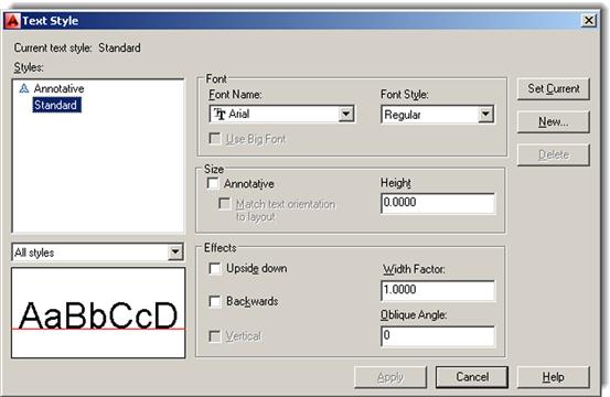
Step 2. Press the New… button and type in the name and size of the font: RomanS_6.
Step 3. Pick romans.shx from the Font Name: drop-down menu.
Step 4. Highlight the 0.0000 in the Height field and type in 6 (no need for the inch symbol). Press Apply and Close.
All text that you type from now on will be RomanS, 6″ font. To create another font just repeat these steps. To size your font up and down, you can also create new font styles, but in this case it may be more practical to just use the scale command.
The additional options in the style dialog box are not used that often but review them just in case. A list follows. All effects can be previewed in real time in the Preview box in the lower right.
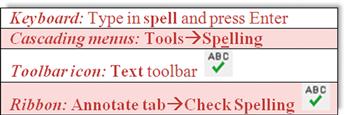
4.5 Spell Check
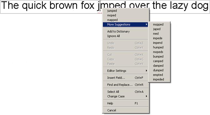
This section briefly describes AutoCAD’s in-place, stand-alone spell checking abilities. Yes, AutoCAD does have a spell checker, and why not? For the price the software costs, it had better. It is very easy to use, so let us try it out on the misspelled phrase shown in Figure 4.13.
The first thing you notice is that the misspelled word (jumped) is underlined by a dotted red line. If you right-click on the word while in editing mode, you get the in-place spell check with suggestions (Figure 4.14). Simply select the word you want to correct to and AutoCAD obliges.
Now what if you already have a significant amount of text (perhaps from an import) and need to spell check it? Then you can use the stand-alone utility, as described next.
Using any of these methods, the Check Spelling dialog box appears, as seen in Figure 4.15.
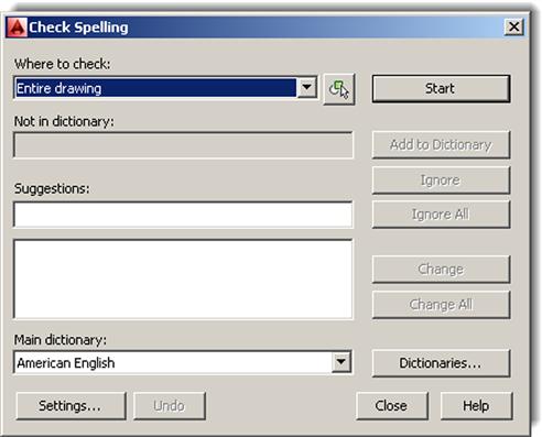
Using the drop-down menu of the Check Spelling dialog box, you can select specific paragraphs or lines of text, or just press Start to initiate spell checker for all the text in the drawing. In any case, Check Spelling appears as seen in Figure 4.16.
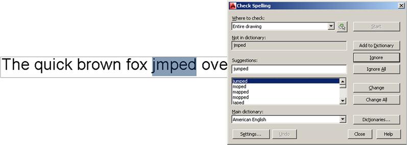
Much like with the MS Word spell checker, you can run through some options, such as ignoring the word, changing it, or adding it to the dictionary so it is not flagged again (good for names and acronyms). There is even a variety of languages available. When done, spell checker tells you, and you can close it.
4.6 In-Class Drawing Project: Adding Text and Furniture to Floor Plan Layout
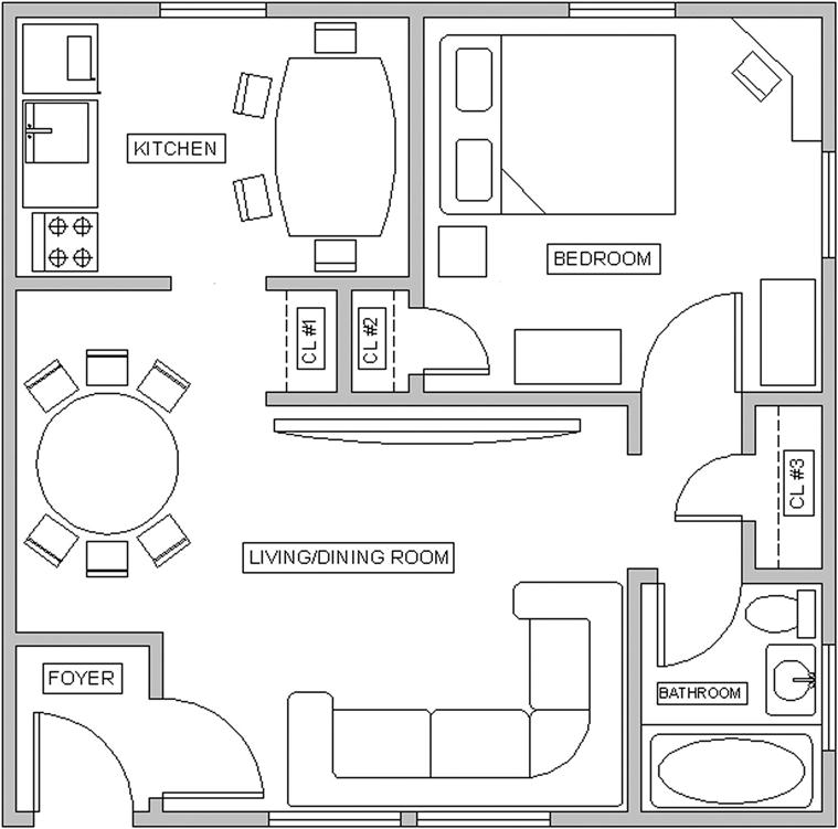
Let us now apply what you learned to our floor plan. Shown in Figure 4.17 is the same floor plan you worked on in Chapter 3, with the addition of text in the rooms, closet shelving (the dashed lines), new furniture, and appliances.
Here are two general tips before you get started:
![]() Make your own layers and colors for each set of data, being sure the names are logical. For example, call kitchen appliances something along the lines of A-Appliances and so on.
Make your own layers and colors for each set of data, being sure the names are logical. For example, call kitchen appliances something along the lines of A-Appliances and so on.
![]() None of the furniture is drawn to scale, so approximate all the sizes. However, draft everything carefully, connecting all lines with OSNAP and using Ortho for straight lines. Most shapes are based on rectangles, with some fillets, arcs, and circles. All were done in the simplest manner possible, and you should be able to create them with basic techniques learned in previous chapters. Some hints are listed next.
None of the furniture is drawn to scale, so approximate all the sizes. However, draft everything carefully, connecting all lines with OSNAP and using Ortho for straight lines. Most shapes are based on rectangles, with some fillets, arcs, and circles. All were done in the simplest manner possible, and you should be able to create them with basic techniques learned in previous chapters. Some hints are listed next.
Some additional specific drawing tips:
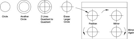
![]() All kitchen furniture on the left side of the kitchen is formed using basic rectangles, drawn to no particular size. At the top left is a refrigerator with a microwave on top. Next to it is a countertop and a sink. Next to that is the range top with four burners. Figure 4.18 is a suggested procedure for creating the range top.
All kitchen furniture on the left side of the kitchen is formed using basic rectangles, drawn to no particular size. At the top left is a refrigerator with a microwave on top. Next to it is a countertop and a sink. Next to that is the range top with four burners. Figure 4.18 is a suggested procedure for creating the range top.
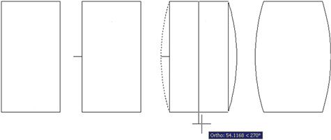
![]() To create the kitchen table you could use a rectangle with a small straight guideline sticking out from the midpoint of the left side. That could be the anchor for the second point of the arc. Then a mirror followed by an explode and erase finishes it off, as seen in Figure 4.19.
To create the kitchen table you could use a rectangle with a small straight guideline sticking out from the midpoint of the left side. That could be the anchor for the second point of the arc. Then a mirror followed by an explode and erase finishes it off, as seen in Figure 4.19.
![]() Draw rectangles around each of the room text fields; we need this later for hatch.
Draw rectangles around each of the room text fields; we need this later for hatch.
![]() The bathtub and toilet are done using the basic ellipse command, introduced in Chapter 2.
The bathtub and toilet are done using the basic ellipse command, introduced in Chapter 2.
![]() The corner desk in the bedroom, the pulled-back bed cover, and all closet shelves are constructed using lines and a new OSNAP point, the second (of three) that was not initially introduced in Chapter 1; a description follows.
The corner desk in the bedroom, the pulled-back bed cover, and all closet shelves are constructed using lines and a new OSNAP point, the second (of three) that was not initially introduced in Chapter 1; a description follows.
NEArest OSNAP
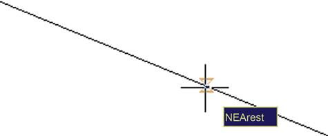
You may occasionally need a new OSNAP point called NEArest. It creates shapes (usually new lines) along random spots of other geometry (usually lines). In a sense, NEArest is the exact opposite of the precise end, mid, and other points you learned. NEArest simply shadows a line or any object and allows you to begin a new object anywhere along that perimeter. We do not generally leave NEArest running along with the other OSNAP points, as it makes using them more difficult; rather, just type it in (NEA) and press Enter, or use the toolbar as needed. An hourglass figure appears; just click on wherever you want to start a line. Figure 4.20 is a screen shot of NEArest in action.
Finally we have two more tips. Tip 6 has to do with ltscale, something briefly mentioned in Chapter 3. Tip 7 shows you how to get rid of the UCS icon, something many students ask about.
Summary
You should understand and know how to use the following concepts and commands before moving on to Chapter 5:
Exercises
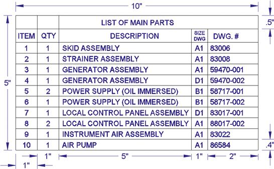
1. Creating tables of data, such as a Bill of Materials (BOM), is an important part of many designs. AutoCAD has a table creation tool (similar to MS Word), which we cover in Level 2, but for this exercise, you need to create one from scratch with basic linework and the offset command, populating it with text data, as shown. Open a blank file and create a new style called RomanS.2; choose font: RomanS, height: .2, and width factor: 0.95. Then create the table shown, using the suggested sizing. Finally, fill in the data, using your choice of text or mtext commands. Position and size the text/mtext as needed. (Difficulty level: Easy; Time to completion: 20 minutes.)
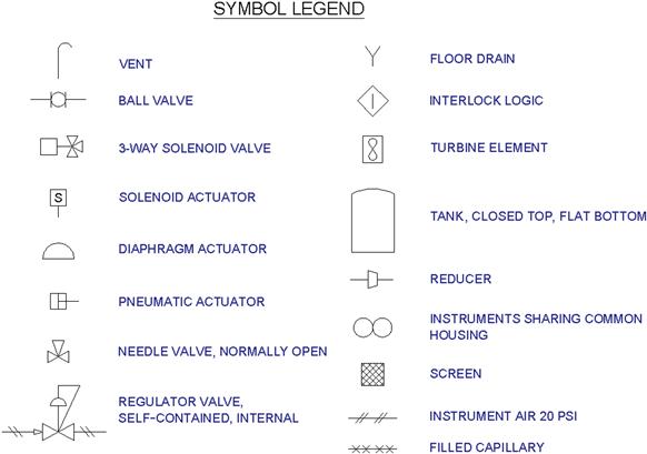
2. As seen with Exercise 6 of Chapter 3 (electrical pieces), you may be asked to draft something based on a picture and use arbitrary, not strict, design dimensions. You need to be fast and efficient while maintaining strict accuracy. A good grasp of the basics is essential, and you must know exactly how you will draft something in your mind, just moments before your fingers do it via mouse and keyboard. Such is the nature of this next exercise—to build up this accuracy and speed. Draw the following set of P&ID (piping and instrumentation diagram) symbols. They are not to scale and are approximated, but you have all of the necessary tools at your disposal. Before drafting each shape, recite to yourself the approach you will use, then execute it. Finally, add the text next to the respective symbols. Use the Arial font of appropriate size. (Difficulty level: Intermediate; Time to completion: 35–45 minutes.)
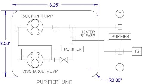
3. This exercise shows a simple P&ID schematic using some additional industry symbols. Draft it based on the reference dimensions given, with all internal pieces and text sizing estimated in relation to those. Use accuracy, connecting all lines with OSNAPs. (Difficulty level: Easy/Intermediate; Time to completion: 20–30 minutes.)
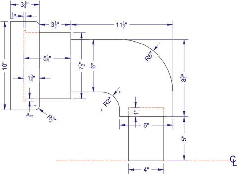
4. While we are on the subject of P&ID, let us create a simplified design of a pipe. Open a new file and set up Architectural units, creating proper layers, colors, and linetypes (Hidden and Center), as shown. Then, draw the following pipe design. Be careful in how you approach the hidden lines, noting that they are on the same plane as the solid lines. This is commonly seen on mechanical drawings. (Difficulty level: Intermediate; Time to completion: 15–20 minutes.)
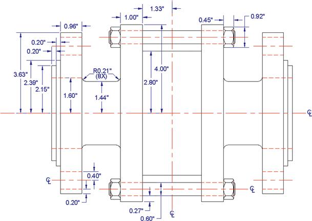
5. Valves are an important part of P&IDs. In a new file, set up the units as Architectural and set up layers M-Part, Hidden, and Center, assigning those proper linetypes and colors of your choosing. Then, draw the valve shown. Be sure to use the mirror command wisely to avoid duplication of drawing effort. The hex nuts are not specifically detailed out; you have to improvise. (Difficulty level: Intermediate/Advanced; Time to completion: 45–60 minutes.)
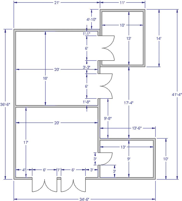
6. This exercise involves a floor plan. Similar to previous activities, open a new file, set up A-Walls and A-Doors layers and colors, and leave your units as Architectural. Then, complete the following basic floor plan. All walls are 6″ thick. All the doors are 3′ wide and have no thickness; you may give them thickness if you like. (Difficulty level: Intermediate; Time to completion: 45–60 minutes.)
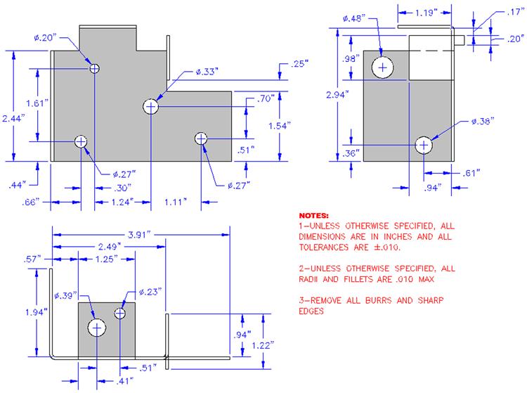
7. The exercise is a mechanical bracket, projected in top, front, and side views, a very typical mechanical engineering/machine design project. Open a new file, set up your units as Decimal, and draw the shapes as shown. The dimensions and shading are for your use and clarity; we cover both shortly. Since you have learned the text and mtext commands, be sure to add the notes. (Difficulty level: Intermediate/Advanced; Time to completion: 60 minutes.)