Advanced Output—Paper Space
Learning Objectives
In this chapter, we introduce and thoroughly cover the concept of Paper Space. We specifically introduce:
![]() The primary reasons for using Paper Space
The primary reasons for using Paper Space
![]() Entering Paper Space and setting up title blocks (Layouts)
Entering Paper Space and setting up title blocks (Layouts)
![]() Viewports and their properties
Viewports and their properties
![]() Controlling what is visible in viewports
Controlling what is visible in viewports
![]() Setting up text and dim styles based on the viewport scale
Setting up text and dim styles based on the viewport scale
![]() The new Annotation feature that simplifies setup of text and dims
The new Annotation feature that simplifies setup of text and dims
By the end of the chapter, you will be well versed in applying this critical concept to your design work.
Estimated time for completion of chapter: 3 hours.
10.1 Introduction to Paper Space
Paper Space is an extensive and critically important topic in AutoCAD. Learning it is a rite of passage for all AutoCAD designers, and proper setup and use of Paper Space is a mark of an expert user. The topic is not necessarily difficult but can be somewhat tedious, requiring care and attention from the designer who really has to “dot the Is and cross the Ts” to assure everything is done right. It is also a topic that needs to be understood well in theory, first and foremost. The actual “button pushing” process to set things up is much easier when you understand what Paper Space is and why it is used. The result of learning all this, however, is a professional drawing set that is accurate and easy to read, understand, and print. This is a necessity and a goal well worth striving for. We explore Paper Space from all angles, one step at a time. Read and understand each section before moving on to the next, as the knowledge is cumulative.
What is Paper Space?
When you create a design of a building with pencil and paper, this design needs to be drawn to a certain scale, as opposed to full-size, for the simple reason that it would not fit on a piece of paper if you did not do this. This is the reason why architects carry with them an architectural scale, a portion of which is shown in Figure 10.1.
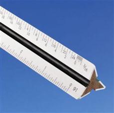
Then, they can simply pick the appropriate scale for the size of their intended design (1⁄8"=1’–0" is common), and now, because 8 feet are represented by 1 inch, the building floor plan can fit nicely on a large sheet of paper.
In AutoCAD, however, you do not draw “to scale.” Because you now have an infinite-size canvas upon which to create your design, everything is drawn one to one (1:1) or “life size,” meaning that, if you were to jump into your design through the computer monitor, you would find yourself in proportion to (and would be able to freely walk around inside) your building.
This is one of the Golden Rules of AutoCAD, and indeed in all of computer-aided design, and marks a significant departure in philosophy and method from the previous hand-drafting approach. In fact, attempting to draw “to scale” results in severe complications and potential for error when creating, and later changing, the design and is simply not done in practice.
Drawing one to one, however, creates a whole new set of problems. How do you output a design that may be dozens or hundreds of feet across, onto a paper that is generally only 3 or 4 feet wide? Furthermore, this design has to be framed by a title block or title page that itself has to be drawn one to one, so as to not violate the Golden Rule. The solution is elegant, simple in principle, and has stood the test of time.
The idea is as follows: Draw the design in one area of AutoCAD, called Model Space, then draw the title block in another unconnected and unrelated area, called Paper Space. Finally, connect the two together via a tool called a viewport, which is simply a “window” looking in from Paper Space onto Model Space. This viewport is then assigned an appropriate scale; and if everything is drawn (and printed) one to one from Paper Space, then the design comes out to scale and the problem is resolved.
This in essence is Paper Space: Nothing more than a technique to separate the two worlds and reconcile them in a meaningful way to get around the tricky problem of a finite-size piece of paper holding a much larger design.
Be sure you understand the previous few paragraphs completely. Everything outlined from here on is easier to understand once you have a good idea of why we are doing what we are doing.
10.2 Paper Space Concepts
The devil, as they say, is in the details, and the study of Paper Space involves a number of separate concepts, each of which is an important part of the complete picture and needs to be looked at closely:
![]() Layouts: Entering Paper Space and setting up title blocks.
Layouts: Entering Paper Space and setting up title blocks.
![]() Viewports: Viewports and their properties.
Viewports: Viewports and their properties.
![]() Scaling: Viewport scale assignments.
Scaling: Viewport scale assignments.
![]() Layers: Controlling what is visible in viewports.
Layers: Controlling what is visible in viewports.
![]() Text and Dims: Setting up text and dim styles based on viewport scale.
Text and Dims: Setting up text and dim styles based on viewport scale.
![]() Annotation: A new feature that simplifies setup of text and dims.
Annotation: A new feature that simplifies setup of text and dims.
These topics are listed roughly in the order a designer would go through them as he or she sets up and does the project. As an example drawing, we continue using the architectural floor plan that you have been working on since the start of Level 1. It happens to fit nicely on a D-size (36"×24") sheet of paper at ½" scale to illustrate the concepts. If you want to use another design, perhaps one drawn in one of the end-of-chapter exercises or one your instructor assigned to you, by all means use that. If you stick with the apartment floor plan, then thaw all the layers. It may be messy, but we fix that later. Let us begin with the first topic, layouts.
Layouts
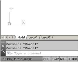
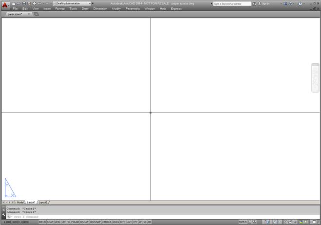
The first step involves switching over to Paper Space and familiarizing yourself with the layout tabs. They are found at the bottom of your drawing area and resemble Microsoft Excel tabs. You will see Model, followed by Layout 1 and Layout 2, as in Figure 10.2.
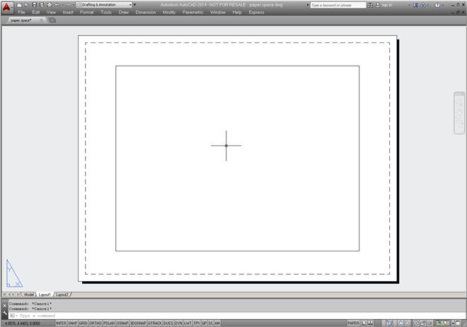
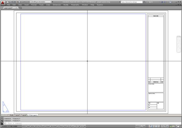
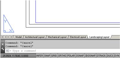
Go ahead and switch into Paper Space by clicking on Layout 1. You notice a different environment, as shown in Figure 10.3. For starters, the UCS icon is a triangle and the Layout 1 tab is highlighted. Your background color is white, and finally you have a variety of background features (rectangles, shadows, viewports, and others). We modify this environment in a minute, but in the meantime, click on the Model tab and jump back into Model Space. You now know how to enter and exit Paper Space.
There really is no need for Paper Space to look any different from Model Space. Nothing is inherently special about Paper Space. Remember, it is just a technique in AutoCAD to create two separate worlds. You can actually draw in Paper Space as if it is your regular drawing area with no adverse effects, but of course that would defeat the whole purpose of what we are doing.
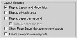
Based on this, it is highly recommended that the Paper Space shadow and other features are turned off. Indeed, most experienced users prefer their Paper Space to look as close to Model Space as possible. It is ultimately up to you if you want to do this, but all screen shots in the remainder of this chapter feature the plain Paper Space environment. To do this, you need to right-click (with the mouse over the command line) to Options…, then select the Display tab and take a look at the Layout elements (lower left). Uncheck all but the very first choice, as seen in Figure 10.4, and set the Sheet/Layout color to black in Colors… (though in the textbook the background remains white to conserve ink and for clarity). It is also a good idea to set your crosshairs to 100 for reasons to be explained later in the chapter. Ask your instructor for assistance if needed. Finally, click on OK.
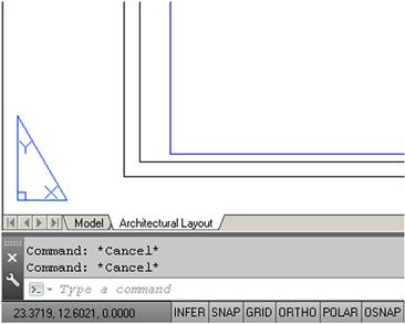
After this modification, Paper Space should look like Figure 10.5 (except of course for the screen color, which should be black, as preferred by most users). Notice that now the only indication that you are in Paper Space is the triangle UCS icon and the highlighted Layout 1 tab. Also the viewport rectangle is erased. Note of course that, if you already had this environment (or a variation of it) set up, you could have skipped the previous few steps.
So, what are these layout tabs in real life? They are actually sheets of paper when the job is completed and ready for printing. The design (done in Model Space) is “presented” in Paper Space with each layout being one sheet of the total drawing set, that is, the Architectural, Mechanical, Electrical, Details, and so on.
If you are thinking that we need to learn how to make title blocks at this point and perhaps create more Layouts, then you are correct. We create a title block from a built-in AutoCAD template. This may or may not be the way you will do it at your job. If you are in an architecture office, there may be a predrawn title block that you can just retrieve and paste in, but for our learning purposes we create a new one.
Select the Layout 1 tab (left-click) then right-click to bring up the menu shown in Figure 10.6.
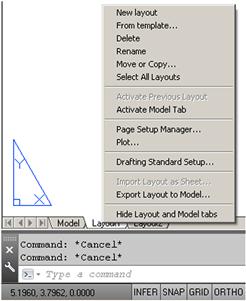
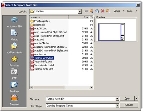
We work with this menu for the next few pages. Let us first of all try creating a title block from a template by clicking on the From template… choice. You get the dialog box seen in Figure 10.7. Pick the Tutorial-iArch.dwt template and click on Open.
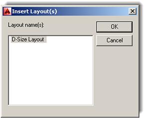
Another small dialog box, Insert Layout(s), appears, as shown in Figure 10.8. It is simply informing you that the layout is a D-size one. Click on OK.
Notice what happened: You have a new tab, called D-Size Layout, positioned right after the other three layouts. Click on it and you see a decent title block, much improved in AutoCAD 2010 versus older releases (AutoCAD 2014 continues to use it). It is a reasonable representation, minus the fancy logos, of what a typical architectural office may use. Inside the title block is a blue rectangle through which you may or may not see your building; this is the viewport, and we cover that topic next. For now, go ahead and delete it. We make our own soon. Also, explode the title block, as we want to modify it.
What you have now is shown in Figure 10.9 (except that your screen background likely is colored black).
The next step is to modify the layout tabs by renaming them to something more descriptive and removing the unnecessary ones. Right-click on the new D-Size layout tab to get the menu to appear again. Select the Rename choice and the tab’s name becomes editable; type in Architectural Layout. Now, get rid of the Layout 1 and Layout 2 tabs, as they are empty and not needed. Begin by clicking on Layout 1, then right-click to get the menu up again. Select Delete and press OK when the warning box pops up. Repeat the procedure for Layout 2. After these steps, we have only two tabs remaining, Model and Architectural Layout, as seen in Figure 10.10.
Take a moment to look over the title block in the Architectural Layout tab. As a reminder, once again, delete the original viewport (the blue rectangle), as we will make our own from scratch. Then, explode the title block if you have not done so yet. Modify anything you may want to look different (for example, delete the user, revdate, and the fname text in the lower left corner), but this is optional.
Now, we need to create more of these title sheets, for the Mechanical and Electrical layouts. Go back to the menu (right-click on the Architectural Layout tab) and select the Move or Copy… choice. The dialog box in Figure 10.11 appears.
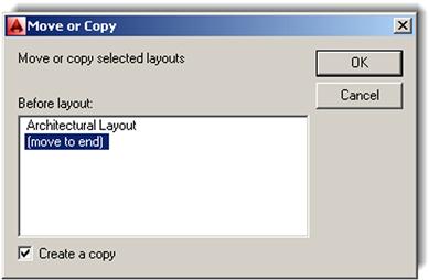
Be sure to do two things. First of all, check off the Create a copy box at the bottom left and click on the (move to end) choice, which simply places the new title sheet next in line after the existing Architectural Layout and may be important later when it comes to the printing order. Finally, click on OK and observe what happens with the tabs. A new one appears, saying Architectural Layout (2), and it is a perfect copy of the previous existing tab. Go ahead and rename it Mechanical Layout. Repeat the whole procedure to create a third tab, called Electrical Layout, and finally a fourth tab, called Landscaping Layout. The final result is in Figure 10.12.
Review this entire section; it is an important first step to learning Paper Space and is a common procedure needed to set up a project that has multiple pages, which is pretty much the case with most projects. It should be clear as to what each sheet (tab) represents. Next, we work on the sheets to set up viewports, so the design can be viewed at the proper scale.
Viewports
Viewports, as mentioned in the introduction, are simply windows from the Paper Space world looking into the Model Space world. It is as if we ripped a hole in the fabric of Paper Space and observed what was behind there. We assign scales to these viewports later on and, in this manner, reconcile the Paper and Model Spaces. For now, we need to first learn how to create and modify the viewports and go over some of their properties. Your new layouts already have a premade viewport (the blue rectangle), but as mentioned earlier, you should have now erased it; we will learn to create a new one from scratch.
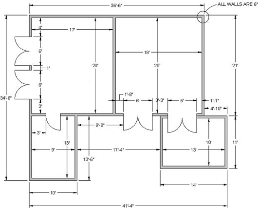
Just a reminder: To go through the following steps, make sure you have a design open to look at, which you already should have, as suggested earlier in this chapter. For an example in this text, the apartment plan from the previous chapters continues to be used. It is slightly modified to include both furniture and floor hatching. You are welcome to duplicate the same thing. If all is well, then let us proceed to learning about the viewport or Mview window.
Click on the Architectural Layout tab, entering Paper Space, type in mview, and press Enter. This is the key command for creating new viewports. Alternatively, you can use the cascading menus View→Viewports→1 Viewport. Note here that you can create more than one viewport at a time, but we do only one for now.
![]() AutoCAD says: Specify corner of viewport or [ON/OFF/Fit/Shadeplot/Lock/ Object/Polygonal/Restore/LAyer/2/3/4]<Fit>
AutoCAD says: Specify corner of viewport or [ON/OFF/Fit/Shadeplot/Lock/ Object/Polygonal/Restore/LAyer/2/3/4]<Fit>
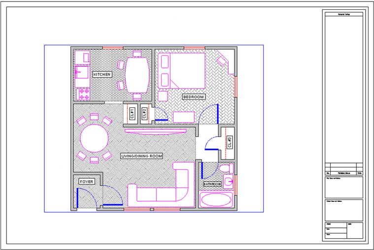
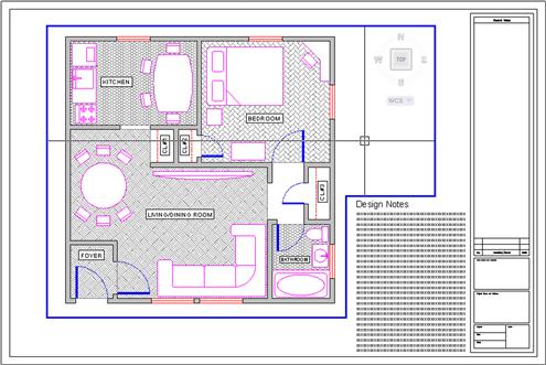
Then simply click and drag the mouse across your screen, effectively drawing a large rectangle from one side of the sheet to the other (avoiding the actual title block in the lower right corner). AutoCAD says: Specify opposite corner: as you are doing this and Regenerating model as you complete the viewport. You should now be able to see the design inside the “rectangle” you created, as shown in Figure 10.13.
You can create more viewports in the other layouts if you like for practice, but we focus on this one, in the Architectural Layout.
Floating Model Space
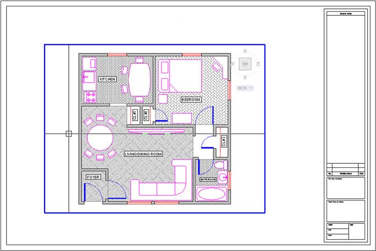
Double-click inside the viewport. Its border becomes thicker and you notice your mouse is “inside” the viewport, as shown in Figure 10.14. The advantage of having full width crosshairs (set at 100) is evident here, as the viewport “clips” the ends of the crosshairs and it becomes clear that you are in this mode. Pan and zoom while inside the viewport and you notice the design shifts around while the Paper Space title sheet stays still. This Floating Model Space mode is sort of a “no man’s land” between the Model and Paper Spaces and is critical in scaling the design, as we shall soon see.
For now, double-click anywhere outside of the viewport to get back to Paper Space. Be careful not to double-click on the viewport itself. That takes you to the vpmax mode (maximum viewport size), which can be used for editing but is not needed here. If you do accidentally double-click on it, press the button shown in Figure 10.15 to get back (bottom right of the screen).

Practice jumping in and out of the viewport several times; this is very important for the rest of the chapter. Note also the big picture discussed so far. You are in Paper Space and created the viewport to look onto the design in Model Space. When you are inside the viewport, you are technically in Model Space but still in Paper Space as well. You need this for scaling purposes only. Design work on either the floor plan or the title sheet or block is done in their respective spaces.
Next, we need to learn how to modify the viewport(s). Note that they are not static displays but rather dynamic tools you can and should mold and shape to your needs, as outlined in the next section.
Modifying the Viewport
First, make sure you are in Paper Space, then click once on the viewport (not inside of it but on the lines of the actual viewport rectangle). The viewport becomes dashed and grips appear. Using them, you can resize the viewport to any size desired by clicking on any grip, activating it (it turns red), and adjusting the viewport’s size and shape. In general, you can:
![]() Scale the viewport(s) up and down to any size.
Scale the viewport(s) up and down to any size.
![]() Adjust the viewport(s) to any shape.
Adjust the viewport(s) to any shape.
![]() Move the viewport(s) anywhere you like.
Move the viewport(s) anywhere you like.
Take a few minutes to go through all these features. Make your viewport smaller, and copy it three times. Move all four around the screen, and erase one. Finally, create it again with mview. In the end, try to have what is shown in Figure 10.16 and make sure you understand viewport manipulation, the mview command, and getting in and out of Floating Model Space. When you are inside the viewport, do not forget to also scale the drawing up or down and zoom to extents. We focus on a precise scale later.
Polygonal Viewport
The shape of the viewport need not be rectangular or square; it can be any shape necessary by using the Polygonal option. To practice this, click over to the Mechanical Layout and create a new viewport using the mview command; however, before clicking to draw the actual viewport, select P for Polygonal in the lengthy menu.
![]() AutoCAD says: Specify start point: and after the first click Specify next point or [Arc/Length/Undo]:
AutoCAD says: Specify start point: and after the first click Specify next point or [Arc/Length/Undo]:
Click your way around in some random fashion (do not overlap the clicks) and press C for Close to close the viewport. What you get after creating a starburst sort of pattern is shown in Figure 10.17. You can see the design inside the oddly shaped viewport.
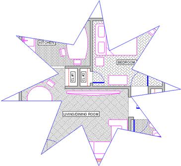
Of course, this is not really what this tool is for. Rather it is to make viewports that weave their way around possible revision blocks or notes on the drawing, thereby freeing you from being forced to use a rectangle and wasting space. An example is shown in Figure 10.18, and this is often the case in real-life designs, making polygonal viewports very important for creating an efficient layout.
There are a few other important items to cover with viewports, such as locking them and making them invisible, but we introduce these features a bit later, as the need arises. What we need to look at next is the “core” of Paper Space: scaling the viewports and their contents.
Scaling
Here, we finally put everything together, because really what we have done so far was just the setup. We have our design in Model Space and our title blocks and sheets in Paper Space, connected together by one or more viewports. Now, we need to give these viewports a scale, which was our goal all along.
To make things simple, let us just have one viewport in our Architectural Layout, so delete any others you may have, including polygonal ones, and leave one large viewport similar to Figure 10.13.
So, what is scaling? Well, you may have already guessed it has something to do with zooming. After all, as the design is zoomed in and out (while in Floating Model Space), the scale continuously changes and is always some value. So scaling the design properly is just a matter of knowing how much to zoom it in the viewport. The big question of course is, How much? Another way to put it is, What scale factor do we apply?
There are two ways to assign scale to any viewport. The first one is a technique used for just about every AutoCAD release up until the last few. It is a bit more involved but really gets you to understand what is going on. Then, we cover the other, easier method.
Method 1. Double-click inside the viewport, type in zoom, and press Enter.
![]() AutoCAD says: Specify corner of window, enter a scale factor (nX or nXP), or [All/Center/Dynamic/Extents/Previous/Scale/Window/Object]<real time>:
AutoCAD says: Specify corner of window, enter a scale factor (nX or nXP), or [All/Center/Dynamic/Extents/Previous/Scale/Window/Object]<real time>:
Here is where you used to pick E for Extents and see the entire drawing fill up your screen. However, notice the enter a scale factor (nX or nXP) choices. This is what we are interested in right now, specifically nXP.
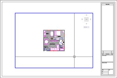
What nXP means is that you need to enter a ratio relative to Paper Space (which is the 1:1 “anchor,” so to speak) and the design scales to that ratio. So, what is it? Well, for ¼"=1’–0", the n is 1/48 (followed by the xP). So type in 1/48xp and press Enter. The design zooms to precisely ¼"=1’–0" scale, as shown in Figure 10.19.
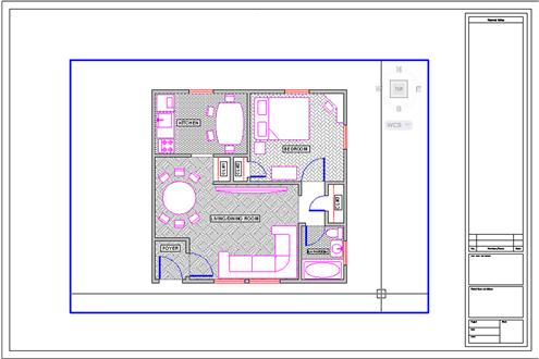
Now, this seems to be too small, doesn’t it? No problem, just type in zoom and press Enter again. Then, type in 1/24xp and press Enter again. The design will zoom to ½"=1’–0", as shown in Figure 10.20, which seems to be a better size for this design and title sheet.
So, where did 1/48xp and 1/24xp come from? They are just ratios developed from the fact that there are 12 inches in 1 foot and the scale is 1/4 or 1/2. Therefore, for 1/4, it is 1/48 (1⁄8 inch scale×1/12 inches in a foot=1/48 relative to the 1:1 Paper Space). For 1/2, it is 1/24 (½ inch scale×1/12 inches in a foot=1/24 relative to the 1:1 Paper Space) and so on. There are additional scales such as 1⁄16", 1⁄8", 3⁄8", 5⁄8", and others, all of which can be derived in a similar manner. Now that you understand basic viewport scaling, let us apply this method in a somewhat easier way.
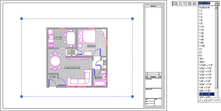
Method 2. Double-click back to Paper Space and bring up the Viewports toolbar, shown in Figure 10.21.
Now click on the viewport once (not inside of it but on the lines of the actual viewport rectangle). When the viewport becomes dashed, the scale associated with that viewport is shown in the white field on the right side of the Viewport toolbar. Click the down arrow and you see a wide variety of choices. Pick the scale you want and the viewport takes on that scale, as shown in Figure 10.22.
Layers
We have done a lot already in setting up the drawing in Paper Space. We now turn our attention to several important details that are either new or change significantly when dealing with Paper Space.
One of those is layers. While the fundamental layer concepts do not change, a new ability is added to the Layers dialog box. It turns out that, when viewports are present, you can freeze and thaw layers in those viewports independent of each other and the main drawing. This is very significant, as you want to be able to display different items as you go from viewport to viewport.
Perhaps the most important example of that is when you jump between the Architectural, Mechanical, and Electrical Layouts. Each tab is a new viewport, yet all views of the design originate from one actual copy of that design. In each layout, you need to see only what is relevant to that layout, and it would be a major problem if you could turn layers on and off only in the main Model Space drawing. Then, each tab would display the exact same thing.
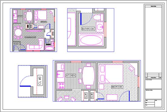
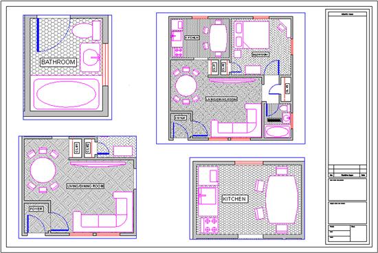
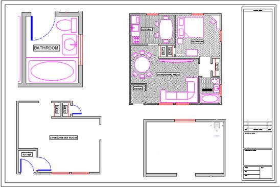
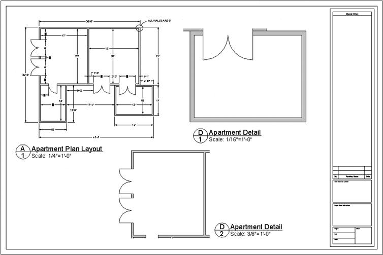
Fortunately, this is not the case, and in each viewport, you can turn layers on and off as needed to get the design points across. Therefore, the Architectural Layout has only architectural layers and so on. It is the same idea with multiple viewports on one layout (such as the case with detail sheets). Each viewport is truly a world unto itself. To see an example of this, let us create four viewports in the Architectural Layout, as shown in Figure 10.23. The scales assigned are random.
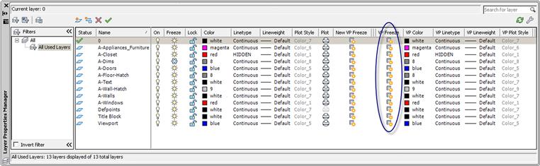
Double-click into the top left viewport and bring up layers. The Layers dialog box (with some extra columns) appears, as shown in Figure 10.24. All relevant columns have been expanded for maximum visibility of the contents. Look for the VP Freeze column (circled); this is the column in which we are interested right now.
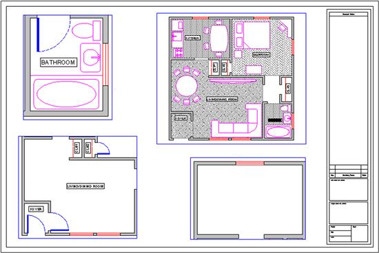
In that column, you can freeze all the unneeded layers for that layout without affecting either the main layout or the other viewports. Go ahead and freeze the A-Floor-Hatch layer. The result is shown in Figure 10.25. Note how the neighboring viewports are not affected by what you did in the top left one. Now click over to the top right one and freeze the A-Doors layer only. Click over to the bottom left viewport and freeze the A-Floor-Hatch, and the A-Appliances_Furniture layers. Finally, in the bottom right viewport, freeze everything except the walls and windows. Note the distinctly different layer settings in each viewport; they are completely independent.
Lock VP
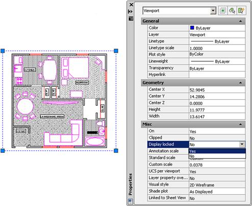
We now cover two other notable features of viewports. The first is the ability to lock the viewport, which simply means you cannot change the viewport’s scale and all zooming attempts fail (the entire Paper Space drawing zooms instead). This can be useful to prevent accidental zooming while inside the viewport and should be set after the design is laid out and set up. To do this, bring up the Properties box. Then, click on the viewport once and select (under Misc.) the Display locked option, setting it to Yes, as shown in Figure 10.26.
Freeze VP
This next feature allows you to either “freeze” the viewport or simply prevent it from printing. The reason for this is that, generally, you do not want a big fat rectangle on your final plots, which will go to the client. This is especially true of the main layouts that feature just one large viewport. The visible viewport rectangle can be mistaken for part of the border and is unnecessary. Even with detail sheets, each of which may display many details, the trend is to just separate them adequately but not have any rectangles visible. If you “did not do it by hand in the old days,” then there is no need to introduce it in AutoCAD.
Having said this, however, some designers prefer to see the viewports all the time and have them disappear only upon printing. So you have several options in this regard.
First of all, we need to put the viewports on an appropriate layer if they are not there already. Designers generally create a_VP layer for them. Notice a trick here. The VP layer has an underscore in front of it. This forces the layer (or any layer that has that underscore) to rise to the top of the layer list, above the 0 layer. This makes it easy to find the title block and sheet or the VP layers, as long as you do not overdo it and stick too many up there. Go ahead and change the color of the layer to gray and freeze it. Then, finally, change all the viewports to that frozen_VP layer. If you did everything correctly, then the viewport boxes disappear, as shown in Figure 10.27.
There are other alternatives, of course, for those who want to see the viewports but not print them. You can put them on the Defpoints layer. This layer does not print (it is the definition points from dimensions). Another method is to just put a slash through the printer icon in the Layers dialog box corresponding to the viewport layer, which leads to the same result.
We are getting to the end of Paper Space; only two major topics are left: text and dims and the Annotation tools.
Text and Dims
This topic is probably the most confusing one in Paper Space and really requires the AutoCAD designer to not only understand everything thoroughly but also work carefully and deliberately. In practice, much of this is done only once and saved as part of a template, but for educational purposes, we assume you are being tasked with the text and dims setup from scratch and must know all the steps.
Our goal here is quite straightforward: We want all the text and dimensions to be the same size when printed, regardless of in what scale viewport they appear. This uniformity is a basic requirement of a professional drawing. Architects and engineers specify something to the effect of: “I want the text height to be ¼" on all drawings, both in layouts and in all details,” and it is up to the AutoCAD designer to ensure that this happens. With hand drafting, this was not an issue; the text and dims were drawn all at once using the same size template.
With AutoCAD, due to our use of Model Space and Paper Space, things are not so simple. The basic fact remains that all text and dimensions have a certain fixed measurable size when drawn in Model Space and appear as different sizes when viewed through the various scaled viewports, just as the design itself does. Some designers try to simplify everything by dimensioning the design in Paper Space to achieve uniformity (AutoCAD lets you do this), but this is not correct. The dimensions and all text must remain with the design in Model Space. The reasons for this are many, not the least of which is that any movement of the design misaligns everything.
So the text and dims need to stay where they are supposed to be, and we need to understand how to properly size text and dimensions based on the anticipated scale of the viewport in which they appear. This all really just boils down to a game of “match-up.” The basic theory is as follows. You already know that viewport scale is a function of zooming. Therefore, when you have uniform text in Model Space and view the same set of text through the ¼"=1’–0" versus the ½"=1’–0" scale viewport in Paper Space, the text in the ½" viewport appears two times as large, as the viewport is a larger scale. To counter this effect, you need to make sure that the text that appears in that ½" viewport is drawn to be half as big, so it appears uniform with the ¼" text (just as an example).
The trick is to be consistent and careful, so that the wrong size text does not appear with the wrong viewport scale. So, how is this done in practice? How do you know what size text and dims are appropriate for a particular scale? We have tables for this, such as the one shown in Figure 10.28.
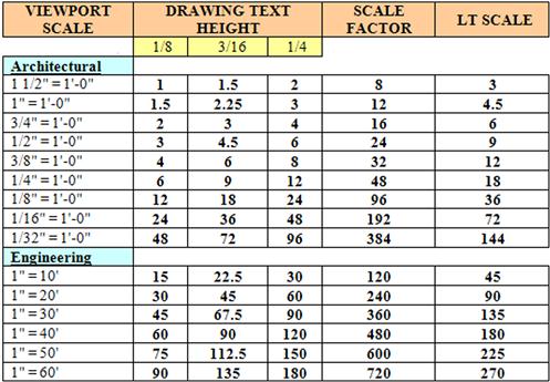
To use this chart, you have to know what scale viewports you are using. With the main layouts, such as the Architectural or Mechanical, done earlier, it is very easy. These layouts typically feature only one viewport of a known scale (⅛"=1’–0" is commonly used); therefore, if the architect desires all text output to be 3/16" in height (also a common size), then by reading the chart from left to right until we meet the 3/16" column, we arrive at a height of 18 inches, which is to be used for all text in that drawing. For the ¼"=1’–0" scale, that same text size is now 9 inches, half as big, since the new scale, ¼"=1’–0", is twice as large.
With details, which may come in all the scales listed, the procedure is no different; you just have to be very careful in knowing ahead of time what scale viewport you are using, to use the appropriate text height. All this comes with experience, and after much practice, you will be able to quickly assess the necessary scale of a given detail to ensure that all aspects of it are visible and clear to whomever is reading the plans. This is the only factor in determining the appropriate text size.
The chart shows not only the text height but also the dimension sizes under the Scale Factor column. Here, you retrieve the appropriate size (24 in the ½"=1’–0" example) and enter that value in the Use overall scale of: text field under the Fit tab of the DDIM dialog box. Also shown is the appropriate scale for linetypes (9 in the case of ½"=1’–0"). You need this to ensure you can see a hidden line, for example, under this scale.
Most of the information contained in Figure 10.28 needs to be entered into AutoCAD in the form of text styles and dim styles. This is the job of the CAD manager on initially setting up an architectural or engineering office’s CAD standards. Yes, it is as tedious as it sounds; the chart is abbreviated and does not contain every scale used, so the work is substantial. Fortunately, it needs to be done only once, and a template is formed for all users to follow from there on out. Enforcing this usually turns out to be the hardest part of all, as the “system” is only as good as the people who follow it. You must be careful to use the proper style (Arial_.25, for example), and be sure to set that style as current while working on the relevant design or detail. The payoff comes later in the process, when you view the design in Paper Space. Uniformity and professionalism is the final goal. Go ahead and practice these concepts.
Step 1. Go to the Style dialog box and create three new text styles, all Arial fonts. They are set up for a final text height of ¼" and are viewed through three viewports of the following scales:
½"=1’–0" (therefore, size: 6").
¼"=1’–0" (therefore, size: 12").
⅛"=1’–0" (therefore, size: 24").
Step 2. Go to the DDIM dialog box and create three new dim styles. All must use the appropriate text from the previous procedure (therefore, the ½"=1’–0" dimension style uses the Arial_.5 style of 6" height, etc.). Then, set the fit as shown on the chart and reproduced here:
½"=1’–0" (therefore, use overall scale of: 24").
¼"=1’–0" (therefore, use overall scale of: 48").
⅛"=1’–0" (therefore, use overall scale of: 96").
Step 3. One by one, in Model Space, set each text and dimension style as current and create one set of text and one set of random dimensions next to each other, as shown in Figure 10.29.
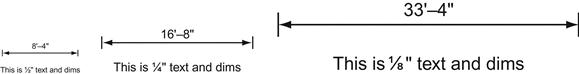
This may take you a few minutes to set up and execute. Be sure to work carefully, checking and rechecking all your settings. As expected, the three scales go up in size twice for each jump from ½" to ¼" to ⅛". We now want to see them uniform in size in Paper Space.
Go into Paper Space and create three viewports next to each other. Use the tools learned previously to set the first one to the ½"=1’–0", the second to ¼"=1’–0", and the third to ⅛"=1’–0". Pan around until the appropriate text and dims combination is in the respective viewport (you may have to go to Model Space and move them apart slightly). The result is shown in Figure 10.30.
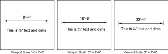
Notice the complete uniformity of the text and dims in Paper Space, as opposed to how they looked in Model Space in Figure 10.29. This is the essence of what we are doing here. If you can set up these three viewports and all the text and dims correctly, you can do any drawing. Be sure to review and learn everything thus far presented. Ask your instructor for assistance if needed.
Annotation
The final Paper Space feature we discuss is relatively new and first appeared in AutoCAD 2008. Called Annotation, its purpose is to present an alternative approach to the methods of the previous section “Text and Dims.” The new approach is different in that it allows you to set multiple scales for the same text, so the proper scales are visible in the proper viewports with no further input from the user. Several items can be annotated: styles, dimensions, blocks, and hatches. We explore text as outlined in the following procedure, but it is similar with dimensions.
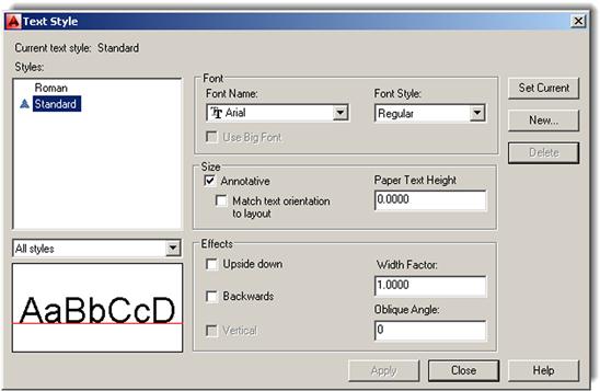
Open a brand-new file, type in style, and press Enter. The familiar Style dialog box comes up. Create a new style, calling it Arial_Anno, font Arial. Check off the Annotative box under Size and leave the Paper Text Height as 0. The new text has a triangular symbol next to it, as seen in Figure 10.31. Be sure to set it as Current.
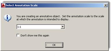
Now switch to Model Space and create a line of text. The first time you do this, a dialog box, such as shown in Figure 10.32, appears. Set the scale at which you anticipate this text to show up in (such as inside a ¼"=1’–0" viewport, as done here). Then press OK and finish typing the text.
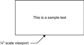
Now, switch to Paper Space and create a viewport and set it to the ¼" scale. Expand or contract it to fit nicely around the text, as shown in Figure 10.33.
Copy that viewport to the right and change its scale to ⅛". The text briefly shrinks to a smaller size, then balloons back up to the same size you set (¼"), as shown in Figure 10.34.
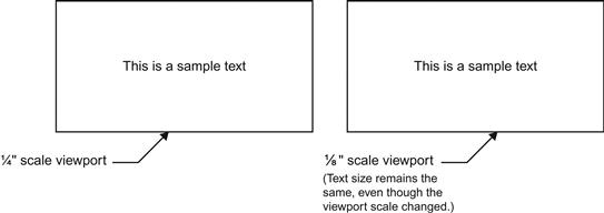
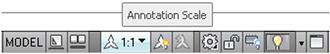
This is the essence of annotation. The Annotation Scale is adjusted at the bottom right of the taskbar, as shown in Figure 10.35, so when new text is being created, you need to set its anticipated viewport scale right away.
You can also set different annotation scales to the same text if you anticipate it being visible in two or more viewports of different scale. Click on the text and a “double” of it pops up (Figure 10.36). This double is not a true copy but a temporary twin. At this point, go ahead and set the new annotation scale from the pop-up list in Figure 10.35 and move the text to a new position (usually right on top of where the old one was).

Everything done here with text can be done with dimensions and the other items listed previously. Experiment with this tool to see exactly what AutoCAD’s designers had in mind. It is not necessarily easier than the previous method but may be somewhat simpler—opinions vary. Note the Annotation Visibility option (scale symbol with a light) next to the Annotation Scale list. This shows all objects in all scales; the symbol next to it is for automatic scale addition.
Summary
We go over a lot of information in this Paper Space chapter. Ideally, you have absorbed all of it and are able to use this valuable and important tool. Many use it improperly or not at all, and being an expert in Paper Space sets you apart from the crowd and adds a true level of professionalism to your designs. This summary serves as a capstone to the chapter and presents the big picture once again, now that the details have been mastered.
Do not think of Paper Space as a rigid or fixed system, where buttons are pushed and results pop out. While an element of this is present, the proper way of looking at it is as a flexible and loose collection of tools that allows you to shape and mold the presentation of your design in a way that is efficient, clear, professional, and of course, pleasing to the eye. There is no one way to do things. Rather there is a constant tug of war between (sometimes conflicting) requirements. For example, you have to consider:
![]() The size of the design. This is the first and foremost concern. Your design takes priority over everything else, so focus on that in Model Space, creating your architectural layout or engineering device, as per client need.
The size of the design. This is the first and foremost concern. Your design takes priority over everything else, so focus on that in Model Space, creating your architectural layout or engineering device, as per client need.
![]() The size of the available plotter and paper. After the design is completed, output is considered. What do you have to work with? Most companies have a plotter capable of 36"×24" plots. Some have the larger 48"×36" plotters. Know your paper options. The larger plotters take E-sized paper, the smaller only up to D size. You cannot print on what you do not have unless you outsource to a print shop.
The size of the available plotter and paper. After the design is completed, output is considered. What do you have to work with? Most companies have a plotter capable of 36"×24" plots. Some have the larger 48"×36" plotters. Know your paper options. The larger plotters take E-sized paper, the smaller only up to D size. You cannot print on what you do not have unless you outsource to a print shop.
![]() The scale needed to clearly see all facets of the design. This is the next important step. Take a look at how your design will look on the D- or E-size sheets. Can you see everything? Are any parts of the design not clearly visible? Generally, a 25’×25’ building (such as the one used as an example in this chapter) fits nicely on a D-size sheet at ½"=1’–0" scale. If it is much bigger, then you can either switch to an E-size sheet (if possible) or switch to another scale. Another scale, however, makes the small details of the design hard to see, so an option is to stay at the previous scale and “split” the drawing into halves or quarters and use match lines for alignment.
The scale needed to clearly see all facets of the design. This is the next important step. Take a look at how your design will look on the D- or E-size sheets. Can you see everything? Are any parts of the design not clearly visible? Generally, a 25’×25’ building (such as the one used as an example in this chapter) fits nicely on a D-size sheet at ½"=1’–0" scale. If it is much bigger, then you can either switch to an E-size sheet (if possible) or switch to another scale. Another scale, however, makes the small details of the design hard to see, so an option is to stay at the previous scale and “split” the drawing into halves or quarters and use match lines for alignment.
As you can see, many variables come into play in setting up Paper Space properly; and with experience, all this will be in your head at the start of a project and you will know instinctively what paper, scale, and viewports to go with, based on the size and expected overall shape of the design.
As of completion of this chapter, you have graduated from a beginner to intermediate level of AutoCAD knowledge. If you have understood everything up to now and have not skipped any exercises or reading, then great job! If all you need AutoCAD for is basic drafting or just knowing enough to oversee other full-time AutoCAD designers, then you may stop here, you have what you need. If your work requires expert level knowledge, you need to go on to Chapters 11 through 20. See you there!
You should understand and know how to use the following concepts and commands before moving on to Level 2 and Chapter 11:
![]() Scaling a design inside of a viewport
Scaling a design inside of a viewport
![]() Working with layers in individual viewports
Working with layers in individual viewports
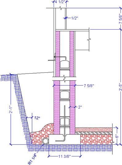
Exercises
1. Set up a total of five title blocks in Paper Space using the Tutorial-iMfg.dwt template file. Name the tabs as seen next, and delete any extra tabs. (Difficulty level: Easy; Time to completion:<10 minutes.)
2. Bring up the floor plan you did in Chapter 4, Exercise 6 (or redraw it). Then, go into Paper Space and create an Architectural Layout tab, followed by several viewports, as in the top figure that follows. Assign each of the viewports a scale as shown in the bottom figure. Freeze the dims layer in the two detail viewports. Note that the floor plan has been rotated 90° clockwise for this exercise. (Difficulty level: Easy; Time to completion: 10–15 minutes if floor plan is completed, 55–75 if not.)
3. The final exercise of this chapter again focuses on the basic drafting of an architectural detail. Set up the proper layers and draft what you see based on the given primary dimensions. Where none are shown, you have to do a reasonable estimate. Note how lines and arcs were used to create borders for some of the hatches, then deleted. This is a common technique that we try again with plines in the next chapter to achieve a smoother effect. (Difficulty level: Moderate; Time to completion: 60–90 minutes.)