
Parabolic Trough and Fresnel Reflector Solar Power Plants
Abstract
A parabolic trough solar plant uses long, trough-shaped solar concentrators to collect solar heat and focus it onto a linear heat absorber. These reflectors track the Sun across the sky for maximum efficiency. Closely related is the Fresnel collection system, which approximates the parabolic trough with long, flat mirrors that can also track the Sun. In both systems a heat collection fluid is pumped through the heat receiver. The heat collected is usually used either directly or indirectly to raise steam and drive a steam turbine generator. Parabolic trough reflectors can achieve a concentration ratio of up to 100. Some parabolic trough plants have been built with heat energy storage, which allows them to operate for longer periods each day. A hybrid solar/natural gas plant can be created by adding a solar collection field to a combined cycle gas turbine plant.
Keywords
Parabolic trough; linear concentrator; Fresnel collector; solar tracking; direct steam system; steam turbine generator; heat energy storage; solar/gas hybrid
The parabolic trough solar power plant takes its name from the trough-shaped reflector that is used to capture and concentrate the solar heat energy. The collector is much longer than it is wide, and has a parabolic cross section. Each trough is aligned on a north–south axis and provided with a system to allow it to track the Sun across the sky. As it follows the movement of the Sun, the reflector focuses the sunlight onto a solar energy receiver that runs along the length of the trough and is positioned at its focus. These concentrators are sometimes called line focusing solar thermal plants because the sunlight is concentrated along a line.
Closely related to the parabolic trough is the Fresnel reflector, a simplified version of the parabolic trough in which the trough shape is approximated by a series of long, flat—or nearly flat—reflectors that are generally mounted on the ground. The solar energy receiver is mounted separately from the reflectors on a framework that places it above the reflectors. This system is not as efficient at concentrating solar energy as the solar trough, but it is significantly cheaper to construct. The aim of the Fresnel design is to achieve simplicity and low capital cost. However, the technology is less well tested than the more conventional solar trough system.
Line Focusing Origins
The parabolic trough is the oldest of the modern solar thermal technologies. The first recorded version is that of a Dr. Maier of Aalen and a Mr. Remshalden of Stuttgart, who developed a system based on a parabolic trough collector to generate steam. Their system was followed in 1912–13 by a facility built in Cairo by U.S. inventor Frank Shuman. The plant used tracking solar troughs to generate steam for a steam engine, although the initial plan was for the plant to generate electricity.1 The project comprised five collectors, each 62 m long and 4 m in width. The steam that the collectors were able to produce was equivalent to a generating capacity of 41 kW.
The next time the technology appeared in commercial form was in the 1980s in California. A company called Luz built nine plants based on solar parabolic troughs between 1984 and 1991. The first of these had a generating capacity of 13.8 MW, and the final plants had capacities of 80 MW. The technology was considered economically marginal when the plants were built, and in 1991 the builder filed for bankruptcy, unable to secure the financing to build a tenth plant. In spite of that, the nine plants continue to operate and generate power as of 2016. No more plants of this type were constructed until 2007, when the technology enjoyed a renaissance. Since then over 30 power plants based on this technology have been built, and it is arguably the most successful solar thermal technology today.
The Fresnel reflector system is based on a similar principle to the Fresnel lens that was originally developed for lighthouses by the French physicist Augustin-Jean Fresnel. The earliest example of a Fresnel reflector for concentrating solar power was developed by an Italian, Giovanni Francia, who patented his work in 1962. A prototype based on his design was built in France in 1964. The technology did not thrive then, but it was picked up again in Australia in the 1990s, where a large-scale demonstration project was built. Since then plants have also been constructed in the United States and in Spain.
Parabolic Trough Technology
A parabolic trough is a special type of solar concentrator that has a parabolic cross section (it is parabolic in two dimensions) but is linear in the third dimension. The result is that the parabolic shape is extended linearly to make a long reflector. The shape of the reflector causes sunlight to be concentrated along a line at the focus of the parabola, a line that runs along the length of the trough. A heat receiver, normally a specially constructed pipe, is positioned exactly at this focus so that it can absorb the heat from the Sun. A heat transfer fluid is pumped through the pipe and carries the heat away. In most plants this fluid passes through a heat exchanger where it heats water to steam; the steam is used to drive a steam turbine generator. A schematic of a parabolic dish power plant is shown in Fig. 4.1.

A single parabolic trough may be up to 150 m in length. However, each trough is normally made up of sections that are generally 5–20 m in length. Each unit may be 5–8 m wide, with more recent plants aiming for greater width. The width is referred to as the aperture of the trough. Trough collectors are around 2 m deep. The modules are assembled together on some form of support structure, which in modern designs is often a space frame constructed from tubular metal sections. Each module must be carefully aligned with its neighbor on the space frame support, and the whole trough must be able to rotate about an axis along its length to track the Sun across the sky. Alignment of the troughs is north–south so that they can track east to west by rotation of the trough.
The traditional means of constructing the modules has been to use glass. The glass is hot-formed in bending plants and the precise shape is achieved using parabolic molds. The back surface is then silvered. Mirrors of this type can achieve 94–98% reflectance. However, this is a relatively expensive construction technique, even with modern technology, and alternatives are being sought. One method that has shown promise uses a polymer sandwich construction with a thin layer of silver between polymer layers to form the reflective surface. These polymer film reflectors are much lighter than glass and the mirrors are much less expensive to fabricate. A typical commercial product is around 60% lighter than the equivalent glass component, and 30–40% less expensive to fabricate.
Another alternative is to construct the reflector from a lightweight metal alloy, or from an acrylic structure with an alloy reflector. Both polymer film and alloy reflectors offer potential savings, but their long-term durability has yet to be proved. Research by the German Aerospace Centre has also suggested that they cannot achieve the same level of reflectivity as glass. With glass mirrors, the collector field is the most expensive part of a parabolic trough plant and can account for up to 50% of the total capital cost.
Parabolic trough reflectors can achieve a solar concentration ratio of between 60 and 100. The solar heat intensity this creates can potentially raise the temperature of a heat transfer medium to around 550°C. In order to achieve this temperature, the heat transfer fluid must be pumped through circuits that pass along several solar troughs. Many such loops will then be connected in parallel to provide the heat to raise steam. The actual temperature reached by the heat transfer fluid depends upon the fluid itself. Many plants use a synthetic oil that must not be heated above 400°C or it will start to decompose. For plants of this type, the temperature at the solar field outlet will typically be maintained at or below 390°C and the inlet temperature at 290°C so that the temperature rises by 100°C during the passage through the solar field.
A major alternative to the use of oil is a direct steam system in which the heat transfer fluid is a water/steam mixture. The advantage is that steam is generated within the solar field without the need for an intermediary heat exchanger, which significantly increases the overall efficiency. In addition, the temperature within the collection pipes is not limited to 400°C, which allows the power plant’s steam turbine to operate at a higher efficiency. One drawback, however, is that a direct steam system creates many engineering challenges due to both the higher temperature in the collector field and the need to manage a water/steam system under changing heat input conditions. Consequently, direct steam production is not commonly used in commercial solar trough power plants.
A key component of the solar plant is the absorber tube that captures the heat needed to raise the temperature of the heat transfer fluid. This is typically a stainless steel tube that has been coated to increase its absorption properties. A typical receiver will be around 70 mm in diameter and built in 4–5 m sections. The receiver tubing may also have fins to aid absorption. The whole unit is then enclosed in a glass envelope, typically 110–120 mm in diameter, and the space between the steel tube and the glass outer envelope is evacuated to reduce heat loss. The steel absorber is mounted into the glass tube using a system of bellows that allows for relative expansion and contraction of the glass and steel. Junctions at the end of each collector must allow for the rotation of the receiver as the collectors track the Sun.
The efficiency of the energy collection system depends on the accuracy of its geometry as well as the efficiency of the heat absorbers. Solar heat capture efficiency can be as high as 75%.
Fresnel Reflectors
The Fresnel reflector system simplifies the parabolic trough design. Instead of using single parabolic reflectors, it mimics the parabolic shape with a set of flat (or almost flat) mirrors mounted at ground level. A schematic of this type of plant is shown in Fig. 4.2. Typical Fresnel systems use 10–20 individual, long, reflecting segments instead of a single trough collector. Like a parabolic trough, these long, flat mirrors can be rotated about their long axes, which are oriented north–south, so that they can track the Sun across the sky. The use of flat mirrors instead of parabolic mirrors substantially reduces the cost of the collector field. In addition, the collection of mirrors focusing sunlight onto a single receiver can be much larger than is possible with a parabolic trough. In principle this also reduces costs because it can reduce the number of loops required for a similar-sized collector field. An additional advantage is that ground-level mounting of the mirrors reduces wind resistance, which can be a problem in desert regions where solar energy is most widely available.

In addition to the simplification resulting from segmenting of the parabolic reflector, the Fresnel system simplifies the heat-receiving system too, by using a set of absorber tubes fixed relative to the mirrors. Since they do not have to move, as would be necessary in the parabolic trough system, construction of the heat receiver circuit is simpler and therefore cheaper.
These simplifications mean that the Fresnel system is not as efficient at collecting and concentrating solar heat as a parabolic trough. A typical plant will achieve a concentration ratio of 30–50, only half that of a parabolic trough plant. Solar collection efficiency is lower too, with a maximum of 70%. On the other hand, these systems can be more compact at around 1–2 ha/MW. In order to increase efficiency, Fresnel reflector plants often use direct steam heat collection systems instead of the oil heat transfer fluid and intermediate heat exchanger common in parabolic trough plants, an option made possible by the simpler heat circuit in this type of plant.
Power Generation
Solar trough and Fresnel reflector power plants generally use steam turbine generators to produce electricity. The heat transfer fluid exiting the solar field is passed through a system of heat exchangers that heat water and convert it into high-pressure steam. Plants often use reheat steam turbine cycles in which the steam turbine is split into two components. The hottest steam exiting the heat exchanger is fed into the first section of the steam turbine. The steam that exits this turbine is then heated again in a unit called a reheater before entering the second section of the turbine, increasing overall efficiency. Steam exiting the second turbine section is condensed, using a water or air-cooled condenser. The steam cycle water exiting the condenser then returns to the heat exchanger where it is preheated using the last of the heat from the heat transfer fluid before the latter is returned to the collector field.
The steam cycle, with a maximum temperature of around 400°C, can reach an efficiency of 35–38%. This yields an overall plant efficiency of 15–16%.
It is possible to boost the output of a solar thermal power plant such as a parabolic trough plant by using supplementary heating. This involves adding some form of gas firing to the heat exchanger. The additional heat input can be used to smooth out variations in solar input during the day and to extend the operation of the plant during the morning and evening hours.
Energy Storage
The amount of time that a solar thermal power plant can actually supply energy to the grid is limited by the fact that solar energy is only available during daylight hours. To circumvent this problem some solar trough power plants include heat energy storage systems. If some of the solar heat is stored during the day it can be used when solar input is no longer available, extending the period during which the solar plant can supply power.
The most common form of heat energy storage used in solar trough power plants involves storing heat in a mixture of nitrates, typically sodium nitrate and potassium nitrate. These materials are solid at room temperature but liquefy between 130°C and 230°C. The liquid can then be heated to between 500°C and 600°C before the nitrates start to decompose. This means that they are well matched to the solar thermal collector field where the heat transfer fluid temperature varies between 300°C and 400°C. A schematic of a plant of this type is shown in Fig. 4.3.

Heat storage is implemented by having a supplementary heat transfer fluid circuit that bypasses the steam generator heat exchanger. Fluid in this part of the circuit passes through a separate heat exchanger where the molten nitrate salt heat storage medium is heated. The storage system itself consists of two tanks, one with cool molten salt and one with hot salt. During energy storage, heat from the collector circuit is used to heat salt from the cold store, which is then passed into the hot store. When the heat energy is required, this process is reversed and the hot molten salt is used to heat the transfer fluid, which carries the heat to the steam generator section of the circuit.
The amount of energy storage that a plant can maintain depends on the size of the collector field. The larger the collector field in relation to the size of the steam turbine, the more heat available for storage. In theory it is possible to size the collector field to store sufficient energy to keep the plant operating 24 hours each day. In practice this is not the most economical design because the collector field is an expensive part of the plant. More typically a plant has energy stored for up to six hours of operation, which extends its output into the late evening.
Commercial Solar Trough Power Plants
Since 2007 when interest in solar thermal technology resumed, around 30 commercial solar trough plants have been built. The majority of these plants are either in Spain or the United States, with a smaller number in the Middle East. The largest of these are two 280 MW facilities in the United States. One of these, in Arizona, covers an area of 780 ha, or 2.8 ha/MW, an area/MW ratio typical of these plants. The collector field consists of 3232 individual troughs, each made up of 10 modules. There are 808 collector field loops, with each loop passing through eight troughs. The solar field inlet temperature is 293°C and the exit temperature is 393°C. In addition, the plant has a molten salt energy storage system that uses two tanks to provide six hours of operation at full power. Total cost of the plant is estimated to be $2 billon.3
A much smaller number of Fresnel reflector power plants have been constructed. The largest is a 100 MW plant in Rajasthan, India. Others are below 50 MW.
Hybrid Solar Thermal Power Plants
Adding supplementary heating to a concentrating solar thermal power plant creates a form of hybrid plant. There is another configuration that involves adding a solar collection field to a traditional natural gas-fired combined cycle power plant. In this case heat from the solar collection field is used to supplement the heat input for the combined cycle power plant. These plants are generally called Integrated Solar Combined Cycle (ISCC) plants. A diagram of a typical ISCC plant is shown in Fig. 4.4.
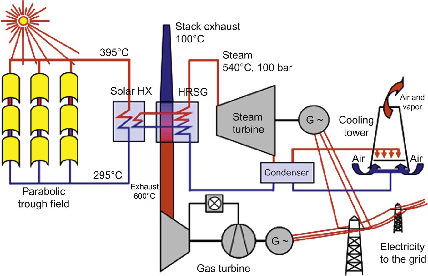
As long as the amount of heat input is kept relatively low compared to the natural gas heat input, the solar efficiency will be much higher than can be achieved in a stand-alone solar trough power station; also, the energy efficiency of the combined cycle power plant is improved. The best balance is achieved when solar input is no more than 10%. If it rises higher, then the effect on the efficiency of the combined cycle plant when solar input falls off at night becomes significant. A low solar input also allows the combined cycle plant to be maintained on standby and kept at operating temperature without burning gas, which increases its flexibility and availability when it is being used for grid support.
A small number of ISCC plants have been built over the past decade. They include projects in the United States, Australia, the Middle East, and Mexico. Solar fields in these plants are generally relatively small, typically under 100 MW, and often less than 50 MW.