Operating Systems
Jean J. Labrosse Founder and Chief Architect, Micrium LLC, Weston, FL, United States
Keywords
Ethernet; Fragmentation; Kernels; Preemptive; Stack size; Task
Real-time systems are systems in which correctness and timeliness of computed values are at the forefront; there are two types—hard and soft real-time systems.
What differentiates hard and soft real-time systems is their tolerance to missing deadlines and the consequences associated with such issues. Correctly computed values supplied after a deadline has passed are often useless.
For hard real-time systems, missing deadlines is not an option. In fact, in many cases, missing a deadline often results in loss of assets or even worse, loss of life. For soft real-time systems, however, missing deadlines is generally not as critical.
Real-time applications are wide ranging, but many real-time systems are embedded. An embedded system is where a computer is built into a system and is typically dedicated to a single use. In other words, they are systems that are designed to perform a dedicated function. The following list provides just a few examples of embedded systems:
- Audio
- MP3 players
- Amplifiers and tuners
- Automotive
- Antilock braking systems
- Climate control
- Engine controls
- Navigation systems (GPS)
- Avionics
- Flight management systems
- Jet engine controls
- Weapons systems
- Office Automation
- FAX machines/copiers
- Home Automation
- Air-conditioning units
- Thermostats
- White goods
- Communications
- Routers
- Switches
- Cell phones
- Process control
- Chemical plants
- Factory automation
- Food processing
- Agriculture
- Round balers
- Square balers
- Windrowers
- Combines
- Video
- Broadcasting equipment
- HD televisions
Real-time systems are typically more complicated to design, debug, and deploy than nonreal-time systems.
1 Foreground/Background Systems
Small systems of low complexity are typically designed as foreground/background systems or super loops, as shown in Fig. 1. An application consists of an infinite loop that calls modules (i.e., tasks) to perform the desired operations (background). Interrupt service routines (ISRs) are designed to handle asynchronous events (foreground events). The foreground is called the interrupt level; the background is called the task level.

Critical operations that should be performed at the task level, but must unfortunately be handled by ISRs to ensure that they are dealt with in a timely fashion, cause ISRs to take longer than they should. Also, information for a background module that an ISR makes available is not processed until the background routine gets its turn to execute, called the task-level response. The worst-case task-level response time depends on how long a background loop takes to execute and, since the execution time of typical code is not constant, the time for successive passes through a portion of the loop is nondeterministic. Furthermore, if a code change is made, the timing of the loop is affected.
Most high-volume low-cost microcontroller-based applications (e.g., microwave ovens, telephones, toys) are designed as foreground/background systems.
2 Real-Time Kernels
A real-time kernel (or simply a kernel) is software that manages the time and resources of a microprocessor, microcontroller, or digital signal processor (DSP). Through functions provided by the kernel, the work of the processor is basically split into tasks, each being responsible for a portion of the job. A task (also called a thread) is a simple program that thinks it has the central processing unit (CPU) completely to itself. On a single CPU, only one task can execute at any given time.
The main function of the kernel is the management of tasks, called multitasking. Multitasking is the process of scheduling and switching the CPU between several tasks. The CPU switches its attention between several sequential tasks. Multitasking provides the illusion of having multiple CPUs and maximizes the use of the CPU. Multitasking also helps in the creation of modular applications. One of the most important aspects of multitasking is that it allows the application programmer to manage the complexity inherent in real-time applications. Application programs are easier to design and maintain when multitasking is used.
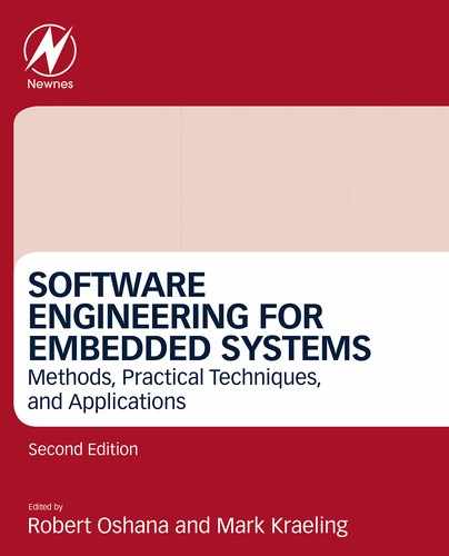
Most real-time kernels are preemptive, which means that the kernel always runs the most important task that is ready-to-run, as shown in Fig. 2.
- (1) A low-priority task is executing.
- (2) An interrupt occurs, and the CPU vectors to the ISR responsible for servicing the interrupting device.
- (3) The ISR services the interrupt device, but does very little work. The ISR will typically signal or send a message to a higher priority task that will be responsible for most of the processing of the interrupting device. For example, if the interrupt comes from an Ethernet controller, the ISR simply signals a task, which will process the received packet.
- (4) When the ISR finishes, the kernel notices that a more important task has been made ready-to-run by the ISR and will not return to the interrupted task, but instead context switches to the more important task.
- (5) The higher priority task executes and performs the necessary processing in response to the interrupt device.
- (6) When the higher priority task completes its work, it loops back to the beginning of the task code and makes a kernel function call to wait for the next interrupt from the device.
- (7) The low-priority task resumes exactly at the point where it was interrupted, not knowing what happened.
Kernels are also responsible for managing communication between tasks and managing system resources (memory and I/O devices).
A kernel adds overhead to a system because the services provided by the kernel require time to execute. The amount of overhead depends on how often these services are invoked. In a well-designed application, a kernel uses between 2% and 4% of a CPU’s time. And, since a kernel is software that is added to an application, it requires extra ROM (code space) and RAM (data space).
3 RTOS (Real-Time Operating System)
A real-time operating system generally contains a real-time kernel and other higher level services, such as file management, protocol stacks, a graphical user interface (GUI), and other components. Most of the additional services revolve around I/O devices.
3.1 Critical Sections
A critical section of code, also called a critical region, is code that needs to be treated indivisibly. There are many critical sections of code contained in typical kernels. If a critical section is accessible by an ISR and a task, then disabling interrupts is necessary to protect the critical region. If the critical section is only accessible by task-level code, the critical section may be protected using a preemption lock.
3.2 Task Management
The design process of a real-time application generally involves splitting the work to be completed into tasks, with each being responsible for a portion of the problem. Kernels make it easy for an application programmer to adopt this paradigm. A task (also called a thread) is a simple program that thinks it has the central processing unit (CPU) all to itself. On a single CPU, only one task can execute at any given time.
Most kernels support multitasking and allow the application to have any number of tasks. The maximum number of tasks is only limited by the amount of memory (both code and data space) available to the processor. Multitasking is the process of scheduling and switching the CPU between several tasks (this will be expanded upon later). The CPU switches its attention between several sequential tasks. Multitasking provides the illusion of having multiple CPUs and maximizes the use of the CPU. Multitasking also helps in the creation of modular applications. One of the most important aspects of multitasking is that it allows the application programmer to manage the complexity inherent in real-time applications. Application programs are typically easier to design and maintain when multitasking is used.
Tasks must be created for the kernel to know about your tasks. You create a task by calling one of the kernel’s services (something like OSTaskCreate()) and you specify as arguments to the function call:
- (1) The start address of the task. In C, this is the name of the function that makes up the task code.
- (2) The priority of the task based on the relative importance of the task.
- (3) The stack space and its size that will be used by the task. In a multitasking environment, each task requires its own stack space.
There are possibly other parameters specific to the task that could be specified. These greatly depend on kernel implementation, however, the above three elements represent the minimum.
When a task is created, it is assigned what’s called a Task Control Block or TCB. The TCB is used to hold runtime information about your task. The TCB is managed by the kernel and the user of the kernel generally doesn’t need to worry about this data structure.
A task can access variables, data structures, or tables that it either owns or shares with other tasks. If these are shared then the application programmer needs to ensure that the task has exclusive access to these variables, data structures, or tables. Fortunately, the kernel provides services that allow you to protect such shared resources. These are discussed later.
A task can also access I/O devices which it can own or share with other tasks. As expected, services are available from the kernel to ensure exclusive access to these I/O devices.
Fig. 3 shows elements that a task can interact with. You should note that the stack is managed by the compiler (function calls, local variables, etc.) and the TCB is managed by the kernel.

Tasks are used for such chores as monitoring inputs, updating outputs, performing computations, controls, updating one or more displays, reading buttons and keyboards, communicating with other systems, and more. One application may contain a handful of tasks while another application may have hundreds. The number of tasks does not represent how good or effective a design may be; it really depends on what the application (or product) needs to do. The amount of work a task performs also depends on the application. One task may have a few microseconds worth of work to perform while another may require tens of milliseconds.
Tasks look like just any other C function except for a few small differences. There are typically two types of tasks: run-to-completion (Listing 1) and infinite loop (Listing 2). In most embedded systems, tasks typically take the form of an infinite loop. Also, no task is allowed to return as other C functions can. Given that a task is a regular C function, it can declare local variables.


A run-to-completion task must delete itself by calling on of the services provided by the kernel. In other words, the task starts, performs its function, and terminates. There would typically not be too many of these tasks in an embedded system because of the generally high overhead associated with “creating” and “deleting” tasks at runtime.
The body of the task can invoke other services provided by the kernel. Specifically, a task can create another task, suspend and resume other tasks, send signals or messages to other tasks, share resources with other tasks, and more. In other words, tasks are not limited to only make “wait for an event” function calls.
You can either call C or assembly language functions from a task. In fact, it is possible to call the same C function from different tasks if the functions are reentrant. A reentrant function is a function that does not use static or otherwise global variables unless they are protected (kernels provide mechanisms for this) from multiple access. If shared C functions only use local variables, they are generally reentrant (assuming that the compiler generates reentrant code). An example of a nonreentrant function is the popular strtok(), provided by most C compilers as part of the standard library. This function is used to parse an ASCII string for “tokens.” The first time you call this function, you specify the ASCII string to parse and a list of token delimiters. As soon as the function finds the first token, it returns. The function “remembers” where it was last, so when it is called again it can extract additional tokens. Two tasks cannot use strtok() at the same time because strtok()can only remember one string position. Thus strtok() is nonreentrant.
The use of an infinite loop is more common in embedded systems because of the repetitive work needed in such systems (reading inputs, updating displays, performing control operations, etc.). This is one aspect that makes a task different than a regular C function. Note that you could use a “while (1)” or “for (;;)” to implement the infinite loop, since both behave the in the same manner—it is simply a matter of personal preference. The infinite loop must call a service provided by the kernel (i.e., function) that will cause the task to wait for an event to occur. It is important that each task wait for an event to occur, otherwise the task would be a true infinite loop and there would be no easy way for other, lower priority tasks to execute.
The event the task is waiting for may simply be the passage of time. Kernels provide “sleep” or “time delay” services. For example, a design may need to scan a keyboard every 50 ms as shown in the pseudocode of Listing 3. In this case, you would simply delay the task for 100 ms then see if a key was pressed on the keyboard and, possibly perform some action based on which key was pressed. Typically, however, a keyboard-scanning task should just buffer an “identifier” unique to the key pressed and use another task to decide what to do as a result of the key(s) pressed.

Similarly, the event the task is waiting for could be the arrival of a packet from an Ethernet controller. The task will have nothing to do until the packet is received. Once the packet is received, the task processes the contents of the packet and possibly moves the packet along a network stack. Kernels provide signaling and message-passing mechanisms.
It is important to note that when a task waits for an event, it does not consume any CPU time.
4 Assigning Task Priorities
Sometimes determining the priority of a task is both obvious and intuitive. For example, if the most important aspect of the embedded system is to perform some type of control, and it is known that the control algorithm must be responsive, then it is best to assign the control task a high priority while display and operator interface tasks are assigned low priority. However, most of the time, assigning task priorities is not so cut and dry because of the complex nature of real-time systems. In most systems, not all of the tasks are considered critical—noncritical tasks should obviously be given a low priority.
An interesting technique called rate monotonic scheduling (RMS) assigns task priorities based on how often tasks execute. Simply put, tasks with the highest rate of execution are given the highest priority. However, RMS makes several assumptions, including that:
- • All tasks are periodic (they occur at regular intervals).
- • Tasks do not synchronize with one another, share resources, or exchange data.
- • The CPU must always execute the highest priority task that is ready-to-run. In other words, preemptive scheduling must be used.
Given a set of n tasks that are assigned RMS priorities, the basic RMS theorem states that all tasks that have hard real-time deadlines are always met if the following inequality holds true:

where Ei corresponds to the maximum execution time of task i, and Ti corresponds to the execution period of task i. In other words, Ei/Ti corresponds to the fraction of CPU time required to execute task i.
Table 1 shows the value for size n(21/n – 1), based on the number of tasks. The upper bound for an infinite number of tasks is given by ln(2), or 0.693, which means that you meet all hard real-time deadlines based on RMS, the CPU usage of all time-critical tasks should be less than 70%!
Table 1
| Number of Tasks | n(21/n − 1) |
|---|---|
| 1 | 1.000 |
| 2 | 0.828 |
| 3 | 0.779 |
| 4 | 0.756 |
| 5 | 0.743 |
| : | : |
| Infinite | 0.693 |
Note that you can still have nontime-critical tasks in a system and thus use close to 100% of the CPU’s time. However, using 100% of your CPU’s time is not a desirable goal as it does not allow for code changes and added features. As a rule of thumb, you should always design a system to use less than 60%–70% of the CPU.
RMS says that the highest rate task has the highest priority. In some cases, the highest rate task might not be the most important task. The application should dictate how to assign priorities. Also, RMS assumes that you know ahead of time the execution of your tasks, which might not be necessarily the case when you start your design. However, RMS is an interesting starting point.
5 Determining the Size of a Stack
The size of the stack required by the task is application specific. When sizing the stack, however, you must account for the nesting of all the functions called by the task, the number of local variables to be allocated by all functions called by the task, and the stack requirements for all nested ISRs (if the ISR uses the task’s stack). In addition, the stack must be able to store all CPU registers and possibly floating- point unit (FPU) registers if the processor has an FPU. In addition, as a rule in embedded systems, avoid writing recursive code.
It is possible to manually figure out the stack space needed by adding all the memory required by all function call nesting (one pointer each function call for the return address), plus all the memory required by all the arguments passed in those function calls, plus storage for a full CPU context (depends on the CPU), plus another full CPU context for each nested ISR (if the CPU doesn’t have a separate stack to handle ISRs), plus whatever stack space is needed by those ISRs. Adding all this up is a tedious chore and the resulting number is a minimum requirement. Most likely you would not make the stack size that precise in order to account for “surprises.” The number arrived at should probably be multiplied by some safety factor, possibly 1.5 to 2.0. This calculation assumes that the exact path of the code is known at all times, which is not always possible. Specifically, when calling a function, such as printf() or some other library function, it might be difficult or nearly impossible to even guess just how much stack space printf() will require. In this case, start with a fairly large stack space and monitor the stack usage at runtime to see just how much stack space is actually used after the application runs for a while.
There are really cool and clever compilers/linkers that provide this information in a link map. For each function, the link map indicates the worst-case stack usage. This feature clearly enables you to better evaluate stack usage for each task. It is still necessary to add the stack space for a full CPU context plus another full CPU context for each nested ISR (if the CPU does not have a separate stack to handle ISRs) plus whatever stack space is needed by those ISRs. Again, allow for a safety net and multiply this value by some factor.
Always monitor stack usage at runtime while developing and testing the product as stack overflows occur often and can lead to some curious behavior. In fact, whenever someone mentions that his or her application behaves “strangely,” insufficient stack size is the first thing that comes to mind.
A task can be in any one of five states as shown in Fig. 4.
- (1) The dormant state corresponds to a task that resides in memory but has not been made available to the kernel. A task is made available to the kernel by calling a function to create the task. The task code actually resides in code space but the kernel needs to be informed about it.
- (2) When the task is no longer needed, your code can call the kernel’s task delete function. The code is not actually deleted, it is simply not eligible to access the CPU.
- (3) A task is in the ready state when it is ready-to-run. There can be any number of tasks ready and the kernel keeps track of all ready tasks in a ready list (discussed later). This list is sorted by priority.
- (4) The most important ready-to-run task is placed in the running state. On a single CPU, only one task can be running at any given time.
- (5) The task selected to run on the CPU is switched in by the kernel when the it determines that it’s the highest priority task that is ready-to-run.
- (6) As previously discussed, tasks must wait for an event to occur. A task waits for an event by calling one of the functions that brings the task to the pending state if the event has not occurred.
- (7) Tasks in the pending state are placed in a special list called a pend list (or wait list) associated with the event the task is waiting for. When waiting for the event to occur, the task does not consume CPU time. When the event occurs, the task is placed back into the ready list and the kernel decides whether the newly readied task is the most important ready-to-run task. If this is the case, the currently running task will be preempted (placed back in the ready list) and the newly readied task is given control of the CPU. In other words, the newly readied task will run immediately if it is the most important task.
- (8) Assuming CPU interrupts are enabled, an interrupting device will suspend execution of a task and execute an ISR. ISRs are typically events that tasks wait for. Generally speaking, an ISR should simply notify a task that an event occurred and let the task process the event. ISRs should be as short as possible and most of the work of handling the interrupting devices should be done at the task level where it can be managed by the kernel.

As the state diagram indicates, an interrupt can interrupt another interrupt. This is called interrupt nesting and most processors allow this. However, interrupt nesting easily leads to stack overflow if not managed properly.
5.1 The Idle Task
Most kernels create an internal task called the idle task. The idle task basically runs when no other application task is able to run because none of the events these tasks are waiting for have occurred. The idle task is the lowest priority task in the application and is a “true” infinite loop that never calls functions to “wait for an event.” This is because, on most processors, when there is “nothing to do,” the processor still executes instructions.
A hook function (also known as a callback) is generally available to the application programmer which can be used to place the CPU in low-power mode for battery-powered applications and thus avoid wasting energy. Typically, most processors exit low-power mode when an interrupt occurs. Depending on the processor, however, the ISR may have to write to “special” registers to return the CPU to its full or desired speed. If the ISR wakes up a high-priority task (every task is higher in priority than the idle task) then the ISR will not immediately return to the interrupted idle task, but instead switch to the higher priority task.
5.2 Priority Levels
All kernels allow you to assign priorities to tasks based on their importance in your application. Typically, a low-priority number means a high priority. In other words, “priority 1” is more important than “priority 10.” The number of different priority levels greatly depends on the implementation of the kernel. It’s not uncommon to have up to 256 different priority levels and thus the kernel can use an 8-bit variable to represent the priority of a task.
On most kernels, an application can have multiple tasks assigned to the same priority. When this priority becomes the highest priority, the kernel generally executes each task at that priority in a round-robin fashion. In other words, each task gets to execute for up to a configurable amount of time.
5.3 The Ready List
Tasks that are ready-to-run are placed in the ready list. The ready list is ordered by priority. The highest priority task is at the beginning of the list and the lower priority tasks are placed at the end of the list. There are techniques that allow inserting and removing tasks from the ready list. However, this is beyond the scope of this chapter.
6 Preemptive Scheduling
The scheduler, also called the dispatcher, is a part of the kernel responsible for determining which task runs next. Most kernels are implemented using a preemptive scheme. The word preemptive means that when an event occurs, and that event makes a more important task ready-to-run, then the kernel will immediately give control of the CPU to that task. Thus when a task signals or sends a message to a higher priority task, the current task is suspended and the higher priority task is given control of the CPU. Similarly, if an ISR signals or sends a message to a higher priority task, when the message has been sent, the interrupted task remains suspended, and the new higher priority task resumes. Preemptive scheduling is illustrated in Fig. 5.
- (1) A low-priority task is executing, and an interrupt occurs.
- (2) If interrupts are enabled, the CPU vectors (i.e., jumps) to the ISR that is responsible for servicing the interrupting device.
- (3) The ISR services the device and signals or sends a message to a higher priority task waiting to service this device. This task is thus ready-to-run.
- (4) When the ISR completes its work it makes a service call to the kernel.
- (5) □
- (6) Since there is a more important ready-to-run task, the kernel decides to not return to the interrupted task but switches to the more important task. This is called a context switch.
- (7) □
- (8) The higher priority task services the interrupting device and, when finished, calls the kernel asking it to wait for another interrupt from the device.
- (9) The kernel blocks the high-priority task until the next time the device needs servicing. Since the device has not interrupted a second time, the kernel switches back to the original task (the one that was interrupted).
- (10) □
- (11) The interrupted task resumes execution, exactly at the point where it was interrupted.

7 Scheduling Points
Scheduling occurs at scheduling points and nothing special must be done in the application code since scheduling occurs automatically based on some conditions described below. This is a partial list for brevity.
- A task signals or sends a message to another task.
- This occurs when the task signals or sends a message to another task.
- A task “sleeps” for a certain amount of time.
- Scheduling always occurs since the calling task is placed in a list waiting for time to expire. Scheduling occurs as soon as the task is inserted in the wait list and this call will always result in a context switch to the next task that is ready-to-run at the same or lower priority than the task that is placed to sleep.
- A task waits for an event to occur and the event has not yet occurred.
- The task is placed in the wait list for the event and, if a nonzero timeout is specified, the task is also inserted in the list of tasks waiting to timeout. The scheduler is then called to select the next most important task to run.
- If a task is created.
- The newly created task may have a higher priority than the task’s creator. In this case, the scheduler is called.
- If a task is deleted.
- When terminating a task, the scheduler is called if the current task is deleted.
- A task changes the priority of itself or another task.
- The scheduler is called when a task changes the priority of another task (or itself) and the new priority of that task is higher than the task that changed the priority.
- At the end of all nested ISRs.
- The scheduler is called at the end of all nested ISRs to determine whether a more important task is made ready-to-run by one of the ISRs.
- A task gives up its time quanta by voluntarily relinquishing the CPU through a kernel call.
- This assumes that the task is running alongside other tasks at the same priority and the currently running task decides that it can give up its time quanta and let another task run.
8 Round-Robin Scheduling
When two or more tasks have the same priority, most kernels allow one task to run for a predetermined amount of time (called a time quanta) before selecting another task. This process is called round-robin scheduling or time slicing. If a task does not need to use its full time quanta it can voluntarily give up the CPU so that the next task can execute. This is called yielding.
9 Context Switching
When the kernel decides to run a different task, it saves the current task’s context, which typically consists of the CPU registers, onto the current task’s stack and restores the context of the new task and resumes execution of that task. This process is called a context switch.
Context switching adds overhead and, the more registers a CPU has, the higher the overhead. The time required to perform a context switch is generally determined by how many registers must be saved and restored by the CPU.
The context switch code is generally part of a processor’s port which adapts the kernel (typically written in C or other higher level languages) to the processor architecture. The latter is typically written in assembly language.
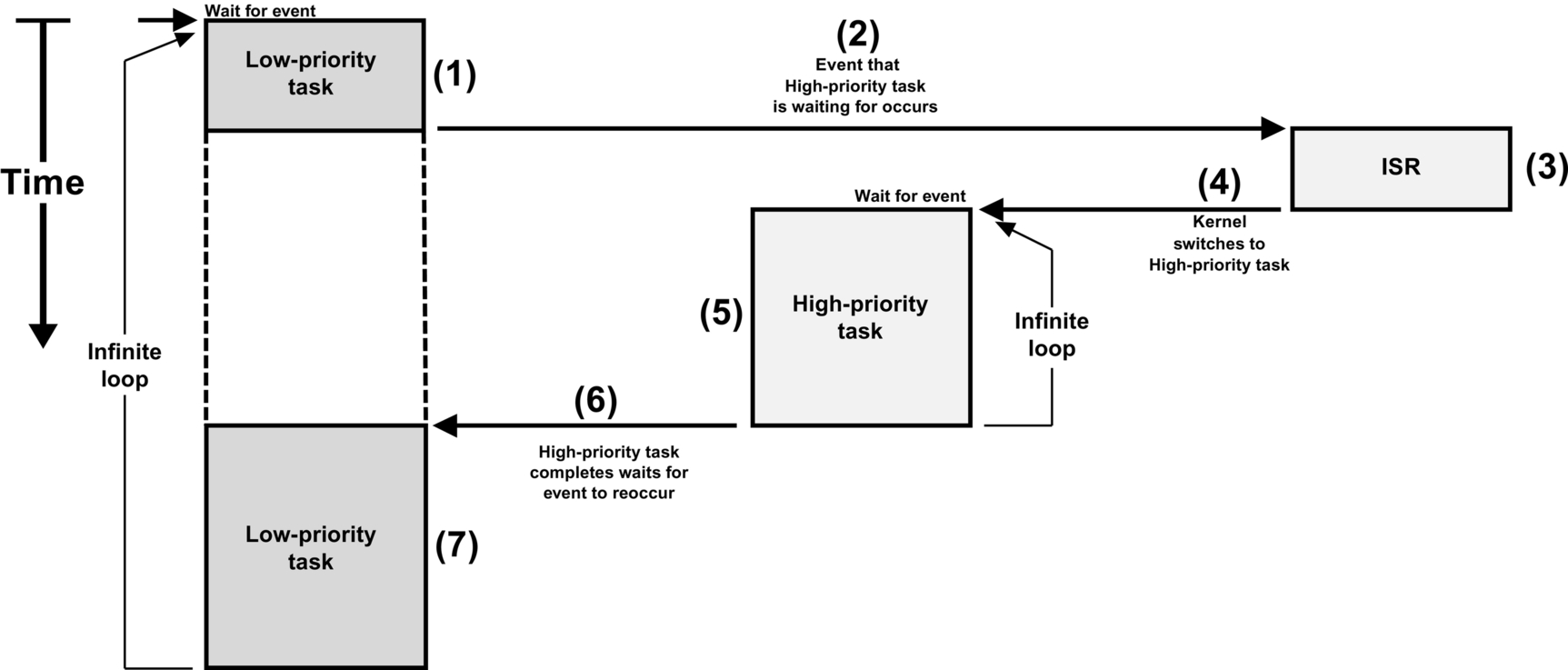
Here, we will discuss the context-switching process in generic terms using a fictitious CPU, as shown in Fig. 6. Our fictitious CPU contains 16 integer registers (R0 to R15), a separate ISR stack pointer, and a separate status register (SR). Every register is 32 bits wide and each of the 16 integer registers can hold either data or an address. The program counter (or instruction pointer) is R15 and there are two separate stack pointers labeled R14 and R14’. R14 represents a task stack pointer (TSP) and R14’ represents an ISR stack pointer (ISP). The CPU automatically switches to the ISR stack when servicing an exception or interrupt. The task stack is accessible from an ISR (i.e., we can push and pop elements onto the task stack when in an ISR), and the interrupt stack is also accessible from a task.

The task initialization code (i.e., the task create function) for a kernel generally sets up the stack frame for a ready task to look as if an interrupt has just occurred and all processor registers were saved onto it. Tasks enter the ready state upon creation and thus their stack frames are preinitialized by software in a similar manner. Using our fictitious CPU, we will assume that a stack frame for a task that is ready to be restored is shown in Fig. 7.

The task stack pointer points to the last register saved onto the task’s stack. The program counter (PC or R15) and status register (SR) are the first registers saved onto the stack. In fact, these are saved automatically by the CPU when an exception or interrupt occurs (assuming interrupts are enabled) while the other registers are pushed onto the stack by software in the exception handler. The stack pointer (SP or R14) is not actually saved on the stack but instead is saved in the task’s control block (TCB).
The interrupt stack pointer points to the current top-of-stack for the interrupt stack, which is a different memory area. When an ISR executes, the processor uses R14’ as the stack pointer for function calls and local arguments.
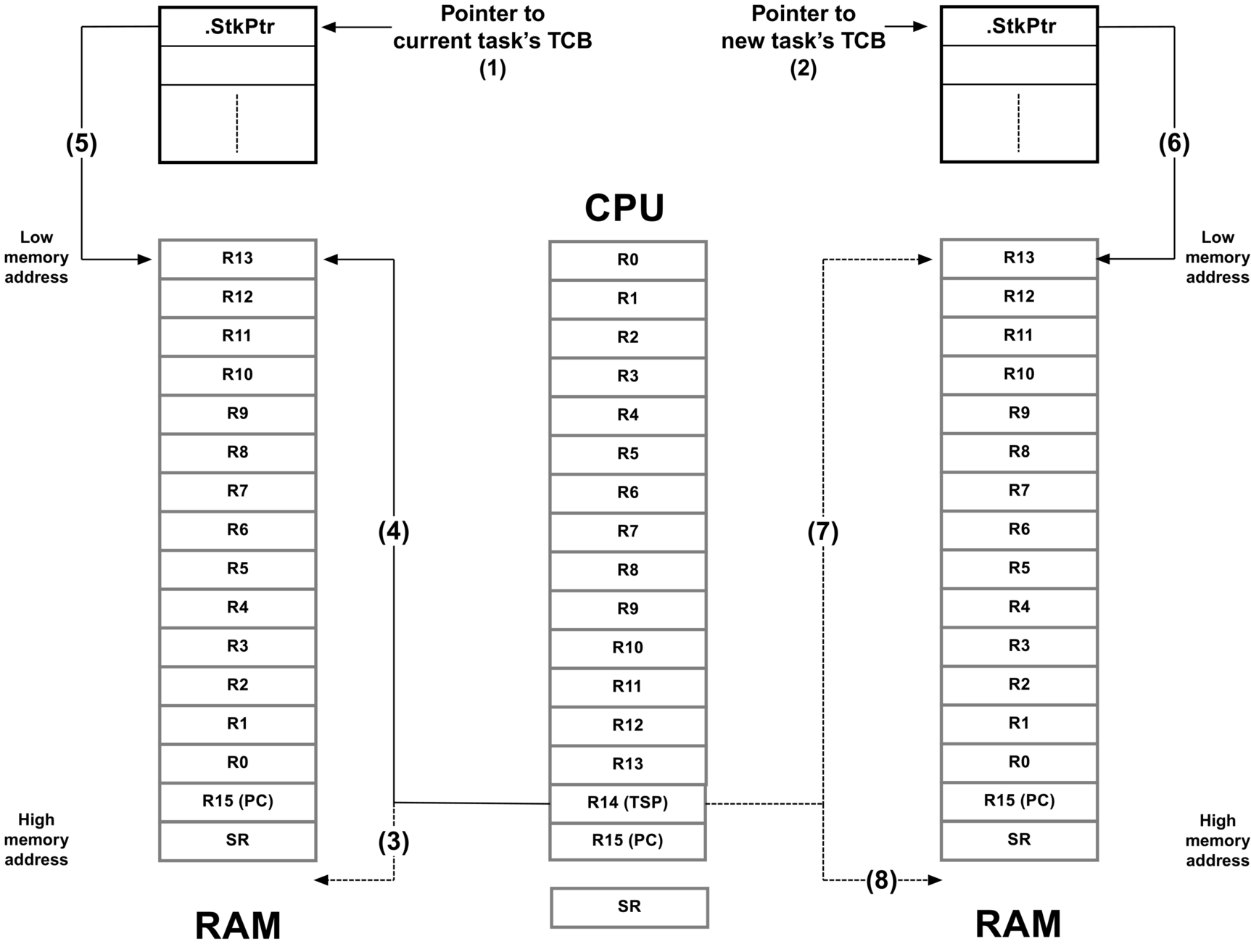
Fig. 8 shows what happens during a context switch.
- (1) The kernel maintains a pointer to the current task’s TCB (task control block).
- (2) Through scheduling, the kernel determined the address of the new task’s TCB.
- (3) The processor’s stack pointer points to the current top-of-stack of the task being switched out.
- (4) The kernel saves all the CPU registers (except the stack pointer itself) onto the current task’s stack.
- (5) The kernel then saves the current value of the CPU’s stack pointer into the TCB of the current task. At this point, the “context” of the CPU of the task being suspended has been completely saved.
- (6) The new task’s TCB contains the value of the top-of-stack of the new task to run.
- (7) The kernel loads the pointer to the new task’s top-of-stack into the CPU’s stack pointer register from the new task’s TCB.
- (8) Finally, the CPU registers are loaded from the stack frame of the new task and, once the PC is loaded into the CPU, the CPU executes the code of the new task.
The execution time of the above process greatly depends on the number of CPU registers to save and restore and, in fact, should be about the same from one kernel to another. Also, a context switch is normally performed with interrupts disabled so that the whole process is treated atomically.
10 Interrupt Management
An interrupt is a hardware mechanism used to inform the CPU that an asynchronous event occurred. When an interrupt is recognized, the CPU saves part (or all) of its context (i.e., registers) and jumps to a special subroutine called an ISR. The ISR processes the event, and—upon completion of the ISR—the program either returns to the interrupted task, or the highest priority task, if the ISR made a higher priority task ready-to-run.
Interrupts allow a microprocessor to process events when they occur (i.e., asynchronously), which prevents the microprocessor from continuously polling (looking at) an event to see if it occurred. Task-level response to events is typically better using interrupt mode as opposed to polling mode. Microprocessors allow interrupts to be ignored or recognized through the use of two special instructions: disable interrupts and enable interrupts, respectively.
In a real-time environment, interrupts should be disabled as little as possible. Disabling interrupts affects interrupt latency, possibly causing interrupts to be missed.
Processors generally allow interrupts to be nested, which means that while servicing an interrupt, the processor recognizes and services other (more important) interrupts.
All real-time systems disable interrupts to manipulate critical sections of code and reenable interrupts when critical sections are completed. The longer interrupts are disabled, the higher the interrupt latency.
Interrupt response is defined as the time between the reception of the interrupt and the start of the user code that handles the interrupt. Interrupt response time accounts for the entire overhead involved in handling an interrupt. Typically, the processor’s context (CPU registers) is saved on the stack before the user code is executed.
Interrupt recovery is defined as the time required for the processor to return to the interrupted code or to a higher priority task if the ISR made such a task ready-to-run.
Task latency is defined as the time it takes from the time the interrupt occurs to the time task-level code resumes.
10.1 Handling CPU Interrupts
There are many popular CPU architectures on the market today, and most processors typically handle interrupts from a multitude of sources. For example, a UART receives a character, an Ethernet controller receives a packet, a DMA controller completes a data transfer, an analog-to-digital converter (ADC) completes an analog conversion, a timer expires, etc.
In most cases, an interrupt controller captures all of the different interrupts presented to the processor, as shown in Fig. 9 (note that the “CPU interrupt enable/disable” is typically part of the CPU, but is shown here separately for sake of the illustration).

Interrupting devices signal the interrupt controller, which then prioritizes the interrupts and presents the highest priority interrupt to the CPU.
Modern interrupt controllers have built-in intelligence enabling the user to prioritize interrupts, remember which interrupts are still pending and, in many cases, have the interrupt controller provide the address of the ISR (also called the vector address) directly to the CPU.
If “global” interrupts (i.e., the switch in Fig. 9) are disabled, then the CPU will ignore requests from the interrupt controller. However, interrupts will be held pending by the interrupt controller until the CPU reenables interrupts.
CPUs deal with interrupts using one of two models:
- 1) All interrupts vector to a single interrupt handler.
- 2) Each interrupt vectors directly to an interrupt handler.
Before discussing these two methods, it is important to understand how a kernel handles CPU interrupts.
In most cases, ISRs are written in assembly language. However, if a C compiler supports in-line assembly language, the ISR code can be placed directly into a C source file. The pseudocode for a typical ISR when using a kernel is shown in Listing 4.
- (1) As mentioned earlier, an ISR is typically written in assembly language. MyKernelAwareISR() corresponds to the name of the handler that will handle the interrupting device.
- (2) It is important that all interrupts are disabled before going any further. Some processors have interrupts disabled whenever an interrupt handler starts. Others require the user to explicitly disable interrupts as shown here. This step may be tricky if a processor supports different interrupt priority levels. However, there is always a way to solve the problem.
- (3) The first thing the interrupt handler must do is save the context of the CPU onto the interrupted task’s stack. On some processors, this occurs automatically. However, on most processors it is important to know how to save the CPU registers onto the task’s stack. You should save the full “context” of the CPU, which may also include floating-point unit (FPU) registers if the CPU used is equipped with an FPU. However, it’s possible that some tasks may not do any floating-point calculations and it would be a waste of CPU cycles to save the FPU registers. Luckily, you can tell some kernels (through task create options) that a task will not require floating-point capabilities.
Certain CPUs also automatically switch to a special stack just to process interrupts (i.e., an interrupt stack). This is generally beneficial as it avoids using valuable task stack space. However, for most kernels, the context of the interrupted task needs to be saved onto that task’s stack.
If the processor does not have a dedicated stack pointer to handle ISRs then it is possible to implement one in the software. Specifically, upon entering the ISR, you would simply save the current task stack, switch to a dedicated ISR stack, and when done with the ISR, switch back to the task stack. Of course, this means that there would be additional code to write, however, the benefits are enormous since it is not necessary to allocate extra space on the task stacks to accommodate for worst-case interrupt stack usage including interrupt nesting. - (4) Next, the ISR would increment a nesting counter to keep track of interrupt nesting. This is done because upon completing the ISR, the kernel needs to know whether it will return to a task or a previous ISR.
- (5) If this is the first nested interrupt, you need to save the current value of the stack pointer of the interrupted task into its TCB.

The previous four steps are called the ISR prolog.
- (6) At this point, the ISR needs to clear the interrupting device so that it does not generate the same interrupt. However, most people defer the clearing of the interrupting device within the user ISR handler which can be written in “C.”
- (7) If the interrupting source has been cleared, it is safe to reenable interrupts if you want to support nested interrupts. This step is optional.
- (8) At this point, further processing can be deferred to a C function called from assembly language. This is especially useful if there is a large amount of processing to do in the ISR handler. However, as a rule, keep the ISRs as short as possible. In fact, it is best to simply signal or send a message to a task and let the task handle the details of servicing the interrupting device.
The ISR must call a kernel function to signal or send a message to a task that is waiting for this event. In other words, most likely you would have designed your task to wait for ISRs to notify them. If the ISR does not need to signal or send a message to a task then you might consider writing the ISR as a “nonkernel-aware interrupt service routine,” as described in the next section. - (9) When the ISR completes, the kernel is notified once more. The kernel simply decrements the nesting counter and if all interrupts have nested (i.e., the counter reaches 0) then the kernel will need to determine whether the task that was signaled or sent a message is now the most important task because it has a higher priority than the interrupted task, or not.
If the task that was waiting for this signal or message has a higher priority than the interrupted task then the kernel will context switch to this higher priority task instead of returning to the interrupted task. In this latter case, the kernel doesn’t return from the ISR but takes a different path. - (10) If the ISR signaled or sent a message to a lower priority task than the interrupted task, then the kernel code returns to the ISR and the ISR restores the previously saved registers.
- (11) Finally, the ISR performs a return from interrupts to resume the interrupted task.
These last three steps are called the ISR epilog.
10.2 NonKernel-Aware Interrupt Service Routine (ISR)
The above sequence assumes that the ISR signals or sends a message to a task. However, in many cases, the ISR may not need to notify a task and can simply perform all its work within the ISR (assuming it can be done quickly). In this case, the ISR will appear as shown in Listing 5.
- (1) As mentioned above, an ISR is typically written in assembly language. MyNonKernelAwareISR() corresponds to the name of the handler that will handle the interrupting device.
- (2) Here, you save sufficient registers required to handle the ISR.
- (3) The user probably needs to clear the interrupting device to prevent it from generating the same interrupt once the ISR returns.
- (4) You should not reenable interrupts at this point since another interrupt could be kernel aware thus forcing a context switch to a higher priority task. This means that the above ISR would complete, but at a much later time.
- (5) Now you can take care of the interrupting device in assembly language or call a C function, if necessary.
- (6) Once finished, simply restore the saved CPU registers.
- (7) The ISR completes by performing a return from interrupt to resume the interrupted task.

10.3 Processors with Multiple Interrupt Priorities
There are some processors that actually support multiple interrupt levels, as shown in Fig. 10.
- (1) Here, we are assuming that the processor supports 16 different interrupt priority levels. Priority 0 is the lowest priority while 15 is the highest. As shown, interrupts are always higher in priority than tasks (assuming interrupts are enabled).
- (2) The designer of the product decided that interrupt levels 0 through 12 will be “kernel aware” and thus will be able to notify tasks that are assigned to service these interrupts. It’s important to note that disabling interrupts (when entering critical sections) for task-aware interrupts means raising the interrupt mask to level 12. In other words, interrupt levels 0 through 11 would be disabled but, levels 12 and above would be allowed.
- (3) Interrupt levels 12 through 15 are “nonkernel aware” and thus are not allowed to make any kernel calls and are thus implemented as shown in Listing 5. It is important to note that since the kernel cannot disable these interrupts, interrupt latency for these interrupts is very short.

Listing 6 shows how to implement nonkernel-aware ISRs when the processor supports multiple interrupt priorities.

10.4 All Interrupts Vector to a Common Location
Even though an interrupt controller is present in most designs, some CPUs still vector to a common interrupt handler, and the ISR needs to query the interrupt controller to determine the source of the interrupt. At first glance, this might seem silly since most interrupt controllers are able to force the CPU to jump directly to the proper interrupt handler. It turns out, however, that for some kernels, it is easier to have the interrupt controller vector to a single ISR handler than to vector to a unique ISR handler for each source. Listing 7 describes the sequence of events to be performed when the interrupt controller forces the CPU to vector to a single location.
- (1) An interrupt occurs from any device. The interrupt controller activates the interrupt pin on the CPU. If there are other interrupts that occur after the first one, the interrupt controller will latch them and properly prioritize the interrupts.
- (2) The CPU vectors to a single interrupt handler address. In other words, all interrupts are to be handled by this one interrupt handler.
- (3) The ISR executes the “ISR prologue” (see Listing 4) code needed by the kernel.
- (4) The ISR calls a special handler which is typically written in C. This handler will continue processing the ISR. This makes the code easier to write (and read). Notice that interrupts are not reenabled at this point.
- (5) The kernel handler then interrogates the interrupt controller and asks: “Who caused the interrupt?” The interrupt controller will either respond with a number (0 to N − 1) or with the address of the interrupt handler of the highest priority interrupting device. Of course, the handler will know how to handle the specific interrupt controller since the C handler is written specifically for that controller.
If the interrupt controller provides a number between 0 and N − 1, the C handler simply uses this number as an index into a table (in ROM or RAM) containing the address of the ISR associated with the interrupting device. A RAM table is handy to change interrupt handlers at runtime. For many embedded systems, however, the table may also reside in ROM.
If the interrupt controller responds with the address of the ISR, the C handler only needs to call this function.
In both the cases above, the ISRs for all the interrupting devices need to be declared as follows:
void MyISRHandler (void);
There is one such handler for each possible interrupt source (obviously, each having a unique name).
The “while” loop terminates when there are no other interrupting devices to service. - (6) Finally, the ISR executes the “ISR epilogue” (see Listing 4) code.

A couple of interesting points to note:
- • If another device caused an interrupt before the C handler had a chance to query the interrupt controller, most likely the interrupt controller will capture that interrupt. In fact, if that second device happens to be a higher priority interrupting device, it will most likely be serviced first, as the interrupt controller will prioritize the interrupts.
- • The loop will not terminate until all pending interrupts are serviced. This is like allowing nested interrupts, but better, since it is not necessary to redo the ISR prologue and epilogue.
The disadvantage of this method is that a high-priority interrupt that occurs after the servicing of another interrupt that has already started must wait for that interrupt to complete before it will be serviced. So, the latency of any interrupt, regardless of priority, can be as long as it takes to process the longest interrupt.
10.5 Every Interrupt Vectors to a Unique Location
If the interrupt controller vectors directly to the appropriate interrupt handler, each of the ISRs must be written in assembly language as described in Section 10.1 and as shown in Listing 4. This, of course, slightly complicates the design. However, you can copy and paste the majority of the code from one handler to the other and just change what is specific to the actual device.
If the interrupt controller allows the user to query it for the source of the interrupt, it may be possible to simulate the mode in which all interrupts vector to the same location by simply setting all vectors to point to the same location. Most interrupt controllers that vector to a unique location, however, do not allow users to query it for the source of the interrupt since, by definition, having a unique vector for all interrupting devices should not be necessary.
11 The Clock Tick (or System Tick)
Kernel-based systems generally require the presence of a periodic time source called the clock tick or system tick.
A hardware timer configured to generate an interrupt at a rate of between 10 and 1000 Hz provides the clock tick. A tick source may also be obtained by generating an interrupt from an AC power line (typically 50 or 60 Hz). In fact, you can easily derive 100 or 120 Hz by detecting zero crossings of the power line. That said, if your product is subject to use in regions that use both power line frequencies then you may need to have the user specify which frequency to use or, have the product automatically detect which region it’s in.
The clock tick interrupt can be viewed as the system’s heartbeat. The rate is application specific and depends on the desired resolution of this time source. However, the faster the tick rate, the higher the overhead imposed on the system.
The clock tick interrupt allows the kernel to delay (also called sleep) tasks for an integral number of clock ticks and provide timeouts when tasks are waiting for events to occur.
A common misconception is that a system tick is always needed with a kernel. In fact, many low-power applications may not implement the system tick because of the power required to maintain the tick list. In other words, it is not reasonable to continuously power down and power up the product just to maintain the system tick. Since most kernels are preemptive, an event other than a tick interrupt can wake up a system placed in low-power mode by either a keystroke from a keypad or other means. Not having a system tick means that the user is not allowed to use time delays and timeouts on system calls. This decision needs to be made by the designer of the low-power product.
11.1 Wait Lists
A task is placed in a wait list (also called a pend list) when it is waiting on a kernel object. A kernel object is generally a data structure that provides an abstraction of a concept, such as a semaphore, mailbox, message queue, or other. Tasks will generally be waiting on these objects to be signaled or posted by other tasks or ISRs.
A wait list is similar to the ready list, except that instead of keeping track of tasks that are ready-to-run, the wait list keeps track of tasks waiting for an object to be signaled or posted. In addition, the wait list is sorted by priority; the highest priority task waiting on the object is placed at the head of the list, and the lowest priority task waiting on the object is placed at the end of the list. A kernel object, along with tasks waiting for this object to be signaled or posted to, is show in Fig. 11. We will be looking at different types of kernel objects in upcoming sections.

11.2 Time Management
Kernels typically provide time-related services to the application programmer.
As previously discussed, kernels require that the user provide a periodic interrupt to keep track of time delays and timeouts. This periodic time source is called a clock tick and should occur between 10 and 1000 times per second (Hertz). The actual frequency of the clock tick depends on the desired tick resolution of the application.
A kernel provides a number of services to manage time: delay (or sleep) for “N” ticks, delay for a user-specified amount of time in seconds and milliseconds, get the current tick count, set the current tick count, and more. Example kernel APIs for these functions could be:
OSTimeDly() or OSTaskSleep()
OSTimeDlySecMilli() or OSTaskSleepSecMilli()
OSTimeGet() or OSTickCntGet()
OSTimeSet() or OSTickCntSet()
A task can call OSTimeDly() to suspend execution until some amount of time expires. The calling function will not execute until the specified time expires. Listing 8 shows a typical use of this function.

The actual delay is not exact, as shown in Fig. 12.
- (1) We get a tick interrupt and the kernel services the ISR.
- (2) At the end of the ISR, all higher priority tasks (HPTs) execute. The execution time of HPTs is unknown and can vary.
- (3) Once all HPTs have executed, the kernel runs the task that has called OSTimeDly(), as shown in Listing 8. For the sake of discussion, it is assumed that this task is a lower priority task (LPT).
- (4) The task calls OSTimeDly() and specifies to delay for two ticks. At this point, the kernel places the current task in the tick list where it will wait for two ticks to expire. The delayed task consumes zero CPU time while waiting for the time to expire.
- (5) The next tick occurs. If there are HPTs waiting for this particular tick, the kernel will schedule them to run at the end of the ISR.
- (6) The HPTs execute.
- (7) The next tick interrupt occurs. This is the tick that the LPT was waiting for and will now be made ready-to-run by the kernel.
- (8) Since there are no HPTs to execute on this tick, the kernel switches to the LPT.

Given the execution time of the HPTs, the time delay is not exactly two ticks, as requested. In fact, it is virtually impossible to obtain a delay of exactly the desired number of ticks. You might ask for a delay of two ticks, but the very next tick could occur almost immediately after calling OSTimeDly()! In fact, imagine what might happen if all HPTs took longer to execute and pushed (3) and (4) further to the right. In this case, the delay would actually appear as one tick instead of two.
12 Resource Management
In this section we will consider the services provided by kernels to manage shared resources. A shared resource is typically a variable (static or global), a data structure, table (in RAM), or registers in an I/O device.
When protecting a shared resource, it is preferable to use mutual exclusion semaphores, as will be described later. Other methods are also presented.
Tasks can easily share data when all tasks exist in a single address space and can reference global variables, pointers, buffers, linked lists, ring buffers, etc. Although sharing data simplifies the exchange of information between tasks, it is important to ensure that each task has exclusive access to the data to avoid contention and data corruption.
For example, when implementing a module that performs a simple time-of-day algorithm in the software, the module obviously keeps track of hours, minutes, and seconds. The TimeOfDay() task may appear as shown in Listing 9.

Imagine this task was preempted by another task, because an interrupt occurred, and that the other task was more important than the TimeOfDay(). Let’s suppose the interrupt occurred after setting the Minutes to 0. Now imagine what will happen if this higher priority task wants to know the current time from the time-of-day module. Since the Hours were not incremented prior to the interrupt, the higher priority task will read the time incorrectly and, in this case, it will be incorrect by a whole hour.
The code that updates variables for the TimeOfDay() task must treat all of the variables indivisibly (or atomically) whenever there is possible preemption. Time-of-day variables are considered shared resources and any code that accesses those variables must have exclusive access through what is called a critical section. All kernels provide services to protect shared resources and enable the easy creation of critical sections.
The most common methods of obtaining exclusive access to shared resources and to create critical sections are:
- • disabling interrupts.
- • disabling the scheduler.
- • using semaphores.
- • using mutual exclusion semaphores (a.k.a. a mutex).
The mutual exclusion mechanism used depends on how fast the code will access a shared resource, as shown in Table 2.
Table 2
| Resource Sharing Method | When should you use? |
|---|---|
| Disable/enable interrupts | When access to a shared resource is very quick (reading from or writing to few variables) and access is faster than the kernel’s interrupt disable time. It is highly recommended to not use this method as it impacts interrupt latency |
| Semaphores | When all tasks that need to access a shared resource do not have deadlines. This is because semaphores may cause unbounded priority inversions (described later). However, semaphore services are slightly faster (in execution time) than mutual exclusion semaphores |
| Mutual exclusion semaphores | This is the preferred method for accessing shared resources, especially if the tasks that need to access a shared resource have deadlines μC/OS-III’s mutual exclusion semaphores have a built-in priority inheritance mechanism, which avoids unbounded priority inversions However, mutual exclusion semaphore services are slightly slower (in execution time) than semaphores since the priority of the owner may need to be changed, which requires CPU processing |
12.1 Resource Management—Disable/Enable Interrupts
The easiest and fastest way to gain exclusive access to a shared resource is by disabling and enabling interrupts, as shown in the pseudocode in Listing 10.

Most kernels use this technique to access certain internal variables and data structures, ensuring that these variables and data structures are manipulated atomically. Note that this is the only way that a task can share variables or data structures with an ISR. Although this method works, you should avoid disabling interrupts as it affects the responsiveness of the system to real-time events.
12.2 Resource Management—Semaphores
A semaphore was originally a mechanical signaling mechanism. The railroad industry used the device to provide a form of mutual exclusion for railroad tracks shared by more than one train. In this form, the semaphore signaled trains by closing a set of mechanical arms to block a train from a section of track that was currently in use. When the track became available, the arm would swing up and the waiting train would then proceed.
The notion of using a semaphore in software as a means of mutual exclusion was invented by the Dutch computer scientist Edgser Dijkstra in 1959. In computer software, a semaphore is a protocol mechanism offered by most multitasking kernels. Semaphores were originally used to control access to shared resources but now are used for synchronization, as described later. However, it is useful to describe here how semaphores can be used to share resources. The pitfalls of semaphores will be discussed in a later section.
A semaphore was originally a “lock mechanism” where code acquired a key to the lock to continue execution. Acquiring a key means that the executing task has permission to enter the section of otherwise locked code. Entering a section of locked code causes the task to wait until a key becomes available.
Typically, two types of semaphores exist: binary semaphores and counting semaphores. As its name implies, a binary semaphore can only take two values: 0 or 1. A counting semaphore allows for values between 0 and 255, 65,535, or 4,294,967,295 depending on whether the semaphore mechanism is implemented using 8, 16, or 32 bits, respectively. Along with the semaphore’s value, the kernel contains a list of tasks waiting for the semaphore’s availability. Only tasks are allowed to use semaphores when semaphores are used for sharing resources; ISRs are not allowed.
Listing 11 shows how semaphores are typically used.
- (1) A semaphore is a kernel object and an application can have any number of semaphores (limited only by the amount of RAM available). The semaphore object must be globally accessible to all tasks that will be sharing the resources guarded by the semaphore.
- (2) A semaphore must be created before it can be used. Creating a semaphore is done by calling a function provided by the kernel. When you create a semaphore, you need to specify its maximum value, which represents the number of resources the semaphore is guarding. In other words, if you are protecting a single variable or data structure, you would create a semaphore with a count of 1. If you are protecting a pool of 100 identical buffers then you’d initialize the semaphore to 100. In the code of Listing 11, the semaphore is initialized to 1—this type of semaphore is typically called a binary semaphore.

Kernel objects are typically created prior to the start of multitasking.
- (3) A task that wants to acquire a resource must perform a wait (or pend) operation. If the semaphore is available (the semaphore value is greater than 0) the semaphore value is decremented and the task continues execution (owning the resource). If the semaphore’s value is 0 the task performing a wait on the semaphore is placed in a waiting list.
- (4) A task releases a semaphore by performing a release (or post) operation. If no task is waiting for the semaphore, the semaphore value is simply incremented. If there is at least one task waiting for the semaphore, the highest priority task waiting on the semaphore is made ready-to-run, and the semaphore value is not incremented. If the readied task has a higher priority than the current task (the task releasing the semaphore), a context switch occurs and the higher priority task resumes execution. The current task is suspended until it again becomes the highest priority task that is ready-to-run.
The application must declare a semaphore as a variable of type OS_SEM. This variable will be referenced by other semaphore services.
You create a semaphore by calling OSSemCreate() and pass the address to the semaphore allocated in (1). The semaphore must be created before it can be used by other tasks. Here, the semaphore is initialized in startup code (i.e., main ()), however, it could also be initialized by a task (but it must be initialized before it is used).
You can assign an ASCII name to the semaphore, which can be used by debuggers or μC/Probe to easily identify the semaphore. Storage for the ASCII characters is usually in ROM, which is typically more plentiful than RAM. If it is necessary to change the name of the semaphore at runtime, you can store the characters in an array in RAM and simply pass the address of the array to OSSemCreate(). Of course, the array must be NUL terminated.
Semaphores are especially useful when tasks share I/O devices. Imagine what would happen if two tasks were allowed to send characters to a printer at the same time. The printer would contain interleaved data from each task. For instance, the printout from Task 1 printing “I am Task 1,” and Task 2 printing “I am Task 2,” could result in “I Ia amm T Tasask k1 2.” In this case, you can use a semaphore and initialize it to 1. The rule is simple: to access the printer each task must first obtain the resource’s semaphore. Fig. 13 shows tasks competing for a semaphore to gain exclusive access to the printer. Note that the key in this figure, indicating that each task must obtain a key to use the printer, represents the semaphore symbolically.

The above example implies that each task knows about the existence of the semaphore to access the resource. It is almost always better to encapsulate the critical section and its protection mechanism. Each task would therefore not know that it is acquiring a semaphore when accessing the resource.
A counting semaphore is used when elements of a resource can be used by more than one task at the same time. For example, a counting semaphore is used in the management of a buffer pool, as shown in Fig. 14.

Let’s assume that the buffer pool initially contains 10 buffers. A task obtains a buffer from the buffer manager by calling BufReq(). When the buffer is no longer needed, the task returns the buffer to the buffer manager by calling BufRel(). The buffer manager satisfies the first 10 buffer requests because the semaphore was initialized to 10. When all buffers are used, a task requesting a buffer is suspended (placed in the semaphore wait list) until a buffer becomes available. When a task is done with the buffer it acquired, the task calls BufRel() to return the buffer to the buffer manager and the buffer is inserted into the linked list before the semaphore is signaled. If there are tasks in the wait list then the buffer is allocated to the highest priority task waiting for a buffer. By encapsulating the interface to the buffer manager in BufReq() and BufRel(), the caller does not need to be concerned with actual implementation details.
12.3 Resource Management—Notes on Semaphores
Using a semaphore to access a shared resource does not increase interrupt latency. If an ISR or the current task makes a higher priority task ready-to-run while accessing shared data, the higher priority task executes immediately.
An application may have as many semaphores as required to protect a variety of different resources. For example, one semaphore may be used to access a shared display, another to access a shared printer, another for shared data structures, and yet another to protect a pool of buffers, etc. However, it is preferable to use semaphores to protect access to I/O devices rather than memory locations.
Semaphores are often overused. The use of a semaphore to access a simple shared variable is overkill in most situations. The overhead involved in acquiring and releasing the semaphore consumes valuable CPU time. You can perform the job more efficiently by disabling and enabling interrupts, however, there is an indirect cost to disabling interrupts: even higher priority tasks that do not share the specific resource are blocked from using the CPU. Suppose, for instance, that two tasks share a 32-bit integer variable. The first task increments the variable, while the second task clears it. When considering how long a processor takes to perform either operation, it is easy to see that a semaphore is not required to gain exclusive access to the variable. Each task simply needs to disable interrupts before performing its operation on the variable and enable interrupts when the operation is complete. A semaphore should be used if the variable is a floating-point variable and the microprocessor does not support hardware floating-point operations. In this case, the time involved in processing the floating-point variable may affect interrupt latency if interrupts are disabled.
Semaphores are subject to a serious problem in real-time systems called priority inversion, which is described next.
12.4 Resource Management—Priority Inversions
Priority inversion is a problem in real-time systems and occurs only when using a priority-based preemptive kernel. Fig. 15 illustrates a priority-inversion scenario. Task H (high priority) has a higher priority than Task M (medium priority), which in turn has a higher priority than Task L (low priority).
- (1) Task H and Task M are both waiting for an event to occur and Task L is executing.
- (2) At some point, Task L acquires a semaphore, which it needs before it can access a shared resource.
- (3) Task L performs operations on the acquired resource.
- (4) The event that Task H was waiting for occurs, and the kernel suspends Task L and starts executing Task H since Task H has a higher priority.
- (5) Task H performs computations based on the event it just received.
- (6) Task H now wants to access the resource that Task L currently owns (i.e., it attempts to get the semaphore that Task L owns). Because Task L owns the resource, Task H is placed in a list of tasks waiting for the semaphore to be available.
- (7) Task L is resumed and continues to access the shared resource.
- (8) Task L is preempted by Task M since the event that Task M was waiting for occurred.
- (9) Task M handles the event.
- (10) When Task M completes, the kernel relinquishes the CPU back to Task L.
- (11) Task L continues accessing the resource.
- (12) Task L finally finishes working with the resource and releases the semaphore. At this point, the kernel knows that a higher priority task is waiting for the semaphore, and a context switch takes place to resume Task H.
- (13) Task H has the semaphore and can access the shared resource.

So, what has happened here is that the priority of Task H has been reduced to that of Task L since it waited for the resource that Task L owned. The trouble began when Task M preempted Task L, further delaying the execution of Task H. This is called an unbounded priority inversion. It is unbounded because any medium priority can extend the time Task H has to wait for the resource. Technically, if all medium-priority tasks have known worst-case periodic behavior and bounded execution times, the priority inversion time is computable. This process, however, may be tedious and would need to be revised every time the medium-priority tasks change.
This situation can be corrected by raising the priority of Task L, for the time it takes to access the resource, and restoring its original priority level when the task is finished. The priority of Task L should be raised to the priority of Task H. In fact, many kernels contain a special type of semaphore that does just that—a mutual exclusion semaphore.
12.5 Resource Management—Mutual Exclusion Semaphores (Mutex)
Some kernels support a special type of binary semaphore called a mutual exclusion semaphore (also known as a mutex) which eliminates unbounded priority inversions. Fig. 16 shows how priority inversions are bounded using a mutex.
- (1) Task H and Task M are both waiting for an event to occur and Task L is executing.
- (2) At some point, Task L acquires a mutex, which it needs before it is able to access a shared resource.
- (3) Task L performs operations on the acquired resource.
- (4) The event that Task H waited for occurs and the kernel suspends Task L and begins executing Task H since Task H has a higher priority.
- (5) Task H performs computations based on the event it just received.
- (6) Task H now wants to access the resource that Task L currently owns (i.e., it attempts to get the mutex from Task L). Given that Task L owns the resource, the kernel raises the priority of Task L to the same priority as Task H to allow Task L to finish with the resource and prevent Task L from being preempted by medium- priority tasks.
- (7) Task L continues accessing the resource, however, it now does so while it is running at the same priority as Task H. Note that Task H is not actually running since it is waiting for Task L to release the mutex. In other words, Task H is in the mutex wait list.
- (8) Task L finishes working with the resource and releases the mutex. The kernel notices that Task L was raised in priority and thus lowers Task L to its original priority. After doing so, the kernel gives the mutex to Task H, which was waiting for the mutex to be released.
- (9) Task H now has the mutex and can access the shared resource.
- (10) Task H is finished accessing the shared resource and frees up the mutex.
- (11) There are no higher priority tasks to execute therefore Task H continues execution.
- (12) Task H completes and decides to wait for an event to occur. At this point, μC/OS-III resumes Task M, which was made ready-to-run while Task H or Task L were executing. Task M was made ready-to-run because an interrupt (not shown in Fig. 16) occurred which Task M was waiting for.
- (13) Task M executes.

Note that there is no priority inversion, only resource sharing. Of course, the faster Task L accesses the shared resource and frees up the mutex, the better.
Kernels should implement full-priority inheritance and therefore if a higher priority requests the resource, the priority of the owner task will be raised to the priority of the new requestor.
Only tasks are allowed to use mutual exclusion semaphores (ISRs are not allowed).
12.6 Resource Management—Deadlocks (or Deadly Embrace)
A deadlock, also called a deadly embrace, is a situation in which two tasks are each unknowingly waiting for resources held by the other.
Assume Task T1 has exclusive access to Resource R1 and Task T2 has exclusive access to Resource R2, as shown in the pseudocode of Listing 12.
- (1) Assume that the event that Task T1 is waiting for occurs and T1 is now the highest priority task that must execute.
- (2) Task T1 executes and acquires Mutex M1.
- (3) Resource R1 is accessed.
- (4) An interrupt occurs causing the CPU to switch to Task T2 since T2 has a higher priority than Task T1.
- (5) The ISR is the event that Task T2 was waiting for and therefore T2 resumes execution.
- (6) Task T2 acquires Mutex M2 and is able to access Resource R2.
- (7) Task T2 tries to acquire Mutex M1, but the kernel knows that Mutex M1 is owned by another task.
- (8) The kernel switches back to Task T1 because Task T2 can no longer continue. It needs Mutex M1 to access Resource R1.
- (9) Task T1 now tries to access Mutex M2 but, unfortunately, Mutex M2 is owned by Task T2. At this point, the two tasks are deadlocked, neither one can continue because each owns a resource that the other one wants.

Some techniques used to avoid deadlocks are for tasks to:
- • Acquire all resources before proceeding.
- • Always acquire resources in the same order.
- • Use timeouts on wait calls (the kernel must provide timeouts on wait calls).
13 Synchronization
This section focuses on how tasks can synchronize their activities with ISRs, or other tasks.
When an ISR executes, it can signal a task telling the task that an event of interest has occurred. After signaling the task, the ISR exits and, depending on the signaled task priority, the scheduler is run.
The signaled task may then service the interrupting device, or otherwise react to the event. Servicing interrupting devices from task level is preferred whenever possible, since it reduces the amount of time interrupts are disabled and the code is easier to debug.
13.1 Synchronization—Semaphores
As previously described, a semaphore is a protocol mechanism offered by most multitasking kernels. Semaphores were originally used to control access to shared resources. However, a mutex is a better mechanism to protect access to shared resources, as previously described.
Semaphores are best used to synchronize an ISR with a task or synchronize a task with another task, as shown in Fig. 17. This is called a unilateral rendez-vous.

Note that the semaphore is drawn as a flag to indicate that it is used to signal the occurrence of an event. The initial value for the semaphore is typically zero (0), indicating the event has not yet occurred.
The value “N” next to the flag indicates that the semaphore can accumulate events or credits. An ISR (or a task) can signal a semaphore multiple times and the semaphore will remember how many times it was signaled. It is possible to initialize the semaphore with a value other than zero, indicating that the semaphore initially contains that number of events.
Also, the small hourglass close to the receiving task indicates that the task has an option to specify a timeout. This timeout indicates that the task is willing to wait for the semaphore to be signaled within a certain amount of time. If the semaphore is not signaled within that time, the kernel will resume the task and return an error code indicating that the task was made ready-to-run because of a timeout and not because the semaphore was signaled.
A few interesting things are worth noting in Fig. 17. First, the task that calls OSSemWait() will not consume any CPU time until it is signaled and becomes the highest priority task ready-to-run. In other words, as far as the task is concerned, it called a function (OSSemWait()) that will return when the event it is waiting for occurs. Second, if the signal does not occur, the kernel maximizes the use of the CPU by selecting the next most important task to run. In fact, the signal may not occur for many milliseconds and, during that time, the CPU will work on other tasks.
Again, semaphores must be created before they can be signaled or waited on.
13.2 Synchronization—Credit Tracking
As previously mentioned, a semaphore “remembers” how many times it was signaled. In other words, if an ISR occurs multiple times before the task waiting for the event becomes the highest priority task, the semaphore will keep count of the number of times it was signaled. When the task becomes the highest priority ready-to-run task, it will execute without blocking as many times as there were ISR signals. This is called credit tracking and is illustrated in Fig. 18 and described in the following text.
- (1) A high-priority task is executing.
- (2) □
- (3) An event meant for a lower priority task occurs which preempts the task (assuming interrupts are enabled). The ISR executes and posts the semaphore. At this point the semaphore count is 1.
- (4) □
- (5) □
- (6) A kernel API is called at the end of the ISR to see if the ISR caused a higher priority task to be ready-to-run. Since the ISR was an event that a lower priority task was waiting for, the kernel will resume execution of the higher priority task at the exact point where it was interrupted.
- (7) The high-priority task is resumed and continues execution.
- (8) □
- (9) The interrupt occurs a second time. The ISR executes and posts the semaphore. At this point the semaphore count is 2.
- (10) □
- (11) □
- (12) The kernel is called at the end of the ISR to see if the ISR caused a higher priority task to be ready-to-run. Since the ISR was an event that a lower priority task was waiting for, the kernel resumes execution of the higher priority task at the exact point where it was interrupted.
- (13) □
- (14) The high-priority task resumes execution and actually terminates the work it was doing. This task will then call one of the kernel services to wait for “its” event to occur.
- (15) □
- (16) The kernel will then select the next most important task, which happens to be the task waiting for the event and will context switch to that task.
- (17) The new task executes and will know that the ISR occurred twice since the semaphore count is two. The task will handle this accordingly.

14 Bilateral Rendez-vous
Two tasks can synchronize their activities by using two semaphores, as shown in Fig. 19. This is called a bilateral rendez-vous. A bilateral rendez-vous is similar to a unilateral rendez-vous, except that both tasks must synchronize with one another before proceeding. A bilateral rendez-vous cannot be performed between a task and an ISR because an ISR cannot wait on a semaphore.

The code for a bilateral rendez-vous is shown in Listing 13.
- (1) Task #1 is executing and signals Semaphore #2.
- (2) Task #1 waits on Semaphore #1. Because Task #2 has not executed yet, Task #1 is blocked waiting on its semaphore to be signaled. The kernel context switches to Task #2.
- (3) Task #2 executes, and signals Semaphore #1.
- (4) Since it has already been signaled, Task #2 is now synchronized to Task #1. If Task #1 is higher in priority than Task #2, the kernel will switch back to Task #1. If not, Task #2 continues execution.

15 Message Passing
It is sometimes necessary for a task or an ISR to communicate information to another task. This information transfer is called intertask communication. Information can be communicated between tasks in two ways: through global data or by sending messages.
As discussed in the Section 12, when using global variables, each task or ISR must ensure that it has exclusive access to variables. If an ISR is involved, the only way to ensure exclusive access to common variables is to disable interrupts. If two tasks share data, each can gain exclusive access to variables either by disabling interrupts, using a semaphore, or preferably, using a mutual exclusion semaphore. Note that a task can only communicate information to an ISR by using global variables. A task is not aware when a global variable is changed by an ISR, unless the ISR signals the task or the task polls the contents of a variable periodically.
Messages can be sent to an intermediate object called a message queue. Multiple tasks can wait for messages to arrive on a message queue and the kernel generally gives the received message to the highest priority task waiting for a message for that queue. When a task waits for a message to arrive, it does not consume CPU time.
15.1 Messages
A message generally consists of a pointer to data instead of copying the actual data. The pointer can point to a data area or even a function. Obviously, the sender and the receiver must agree as to the contents and the meaning of the message. In other words, the receiver of the message will need to know the meaning of the message received to be able to process it. For example, an Ethernet controller receives a packet and sends a pointer to this packet to a task that knows how to handle the packet.
The message contents must always remain in scope since the data is actually sent by reference (i.e., a pointer to the data) instead of by value. In other words, data sent is not copied. You might consider using dynamically allocated memory for the actual message content but you should avoid using allocated memory from the heap because your heap will eventually become so fragmented that your request for memory might not be satisfied. Alternatively, you can pass a pointer to a global variable, a global data structure, a global array, or a function, etc.
15.2 Message Queues
A message queue is a kernel object allocated by the application. In fact, you can allocate any number of message queues. The only limit is the amount of RAM available. There are a number of operations that the user can perform on message queues but the most typical ones are “create a queue,” “send a message through a queue,” and “wait for a message to arrive on a queue.” An ISR can only send a message to a queue; it cannot wait for a message. A message queue must be created before sending messages through it.
Message queues are drawn as a first-in, first-out (FIFO) pipe. However, some kernels allow messages to be sent in a last-in, first-out (LIFO) order. The LIFO mechanism is useful when a task or an ISR must send an “urgent” message to a task. In this case, the message bypasses all other messages already in the message queue. The size of the message queue (i.e., the number of messages that can be held in a queue waiting for processing) is typically configurable either at runtime or configuration time.
Fig. 20 shows typical operations performed on a message queue (queue creation is not shown). The small hourglass close to the receiving task indicates that the task has an option to specify a timeout. This timeout indicates that the task is willing to wait for a message to be sent to the message queue within a certain amount of time. If the message is not sent within that time, the kernel resumes the task and returns an error code indicating that the task was made ready-to-run because of a timeout, and not because the message was received. It is possible to specify an infinite timeout and indicate that the task is willing to wait forever for the message to arrive.

The message queue also contains a list of tasks waiting for messages to be sent to the message queue. Multiple tasks can wait on a message queue as shown in Fig. 21. When a message is sent to the message queue, the highest priority task waiting on the message queue receives the message. Optionally, the sender can broadcast a message to all tasks waiting on the message queue. In this case, if any of the tasks receiving the message from the broadcast have a higher priority than the task sending the message (or interrupted task, if the message is sent by an ISR), the kernel will run the highest priority task that is waiting. Notice that not all tasks must specify a timeout; some tasks may want to wait forever.

16 Flow Control
Task-to-task communication often involves data transfer from one task to another. One task produces data while the other consumes it. However, data processing takes time and consumers might not consume data as fast as it is produced. In other words, it is possible for the producer to overflow the message queue if a higher priority task preempts the consumer. One way to solve this problem is to add flow control in the process, as shown in Fig. 22.

Here, a counting semaphore is used and initialized with the number of allowable messages that can be received by the consumer. If the consumer cannot queue more than 10 messages, the counting semaphore contains a count of 10.
As shown in the pseudocode of Listing 14, the producer must wait on the semaphore before it is allowed to send a message. The consumer waits for messages and, when processed, signals the semaphore.

17 Clients and Servers
Another interesting use of message queues is shown in Fig. 23. Here, a task (the server) is used to monitor error conditions that are sent to it by other tasks or ISRs (clients). For example, a client detects whether the RPM of a rotating wheel has been exceeded, another client detects whether an overtemperature exists, and yet another client detects that a user pressed a shutdown button. When the clients detect error conditions, they send a message through the message queue. The message sent could indicate the error detected, which threshold was exceeded, the error code that is associated with error conditions, or even suggest the address of a function that will handle the error, and more.

17.1 Memory Management
An application can allocate and free dynamic memory using any ANSI C compiler’s malloc() and free() functions, respectively. However, using malloc() and free() in an embedded real-time system may be dangerous. Eventually, it might not be possible to obtain a single contiguous memory area due to fragmentation. Fragmentation is the development of a large number of separate free areas (i.e., the total free memory is fragmented into small, noncontiguous pieces). Execution time of malloc() and free() is generally nondeterministic given the algorithms used to locate a contiguous block of free memory large enough to satisfy a malloc() request.
Kernels provide alternatives to malloc() and free() by allowing an application to obtain fixed-sized memory blocks from a partition made from a contiguous memory area, as illustrated in Fig. 24. All memory blocks are the same size, and the partition contains an integral number of blocks. Allocation and deallocation of these memory blocks is performed in constant time and is deterministic. The partition itself is typically allocated statically (as an array) but can also be allocated by using malloc() as long as it is never freed.

As indicated in Fig. 25, more than one memory partition may exist in an application and each one may have a different number of memory blocks and be a different size. An application can obtain memory blocks of different sizes based upon requirements. However, a specific memory block must always be returned to the partition that it came from. This type of memory management is not subject to fragmentation except that it is possible to run out of memory blocks. It is up to the application to decide how many partitions to have and how large each memory block should be within each partition.

18 Summary
A real-time kernel is software that manages the time and resources of a microprocessor, microcontroller, or DSP. A kernel provides valuable services to your application (product) through a series of application programming interfaces (APIs). Functions are thus available to manage tasks, manage shared resources, notify tasks that events have occurred, send messages to tasks, suspend execution of tasks for a user specified amount of time, and more.
A kernel allows a CPU to multitask. Multitasking is the process of scheduling (determining which task to run next) and context switching (assigning the CPU to a task) the CPU between several tasks. Multitasking provides the illusion of having multiple CPUs and by doing so, maximizes the use of the CPU and helps in the creation of modular applications.
Most real-time kernels are preemptive meaning that the kernel always runs the highest priority task that is ready-to-run.
One of the world’s most popular real-time kernels is called μC/OS-III (pronounced micro-C-OS-three). μC/OS-III is available from Micrium and its source code has been made source available by Micrium. Source available means that the source code can be downloaded from the Micrium website and evaluated for free. However, a license is required if μC/OS-III is used commercially (used with the intent to make a profit).
The internals of μC/OS-III are fully described in the book: μC/OS-III, The Real-Time Kernel published by MicriumPress (see www.micrium.com). There are in fact many versions of the μC/OS-III book, each of which provides examples of running μC/OS-III on different popular CPU architectures (see the Micrium website for details).
This chapter was excerpted from sections of the μC/OS-III book