12.2.2 Counter Current Flow
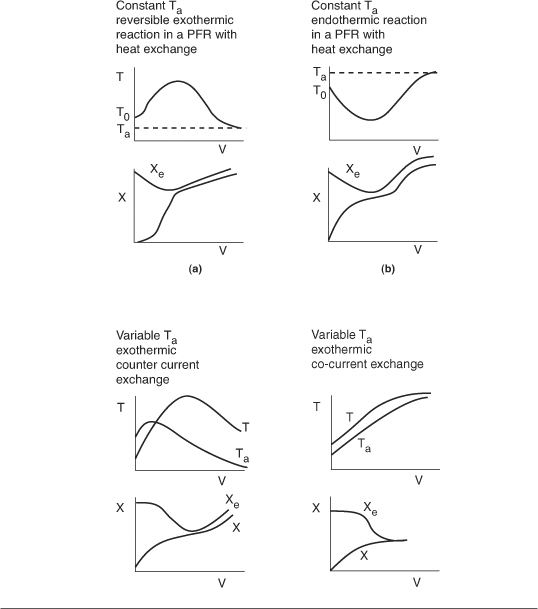
Here the reacting mixture and coolant flow in opposite directions for counter current flow of coolant and reactants. At the reactor entrance, V = 0, the reactants enter at temperature T0, and the coolant exits at temperature Ta2. At the end of the reactor, the reactants and products exit at temperature T, while the coolant enters at Ta0.
Figure 12-4. Counter current, double pipe heat exchanger.
Again we write an energy balance over a differential reactor volume to arrive at.

At the entrance V = 0 ∴ X = 0 and Ta = Ta2.
At the exit V = Vf ∴ Ta = Ta0.
We note that the only difference between Equations (12-10) and (12-11) is a minus sign [i.e., (T – Ta) vs. (Ta – T)].
Solution to a counter current flow problem to find the exit conversion and temperature requires a trial-and-error procedure.
Table 12-1. Procedure to Solve for the Exit Conditions for PFRs with Counter Current Heat Exchange
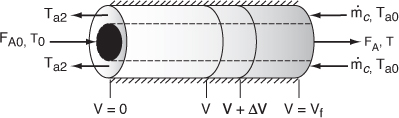
- Consider an exothermic reaction where the coolant stream enters at the end of the reactor (V = Vf) at a temperature Ta0, say 300 K. We have to carry out a trial-and-error procedure to find the temperature of the coolant exiting the reactor.
- Assume an exit coolant temperature at the feed entrance (X = 0, V = 0) to the reactor to be Ta2 = 340 K, as shown in Figure 12-5(a).
- Use an ODE solver to calculate X, T, and Ta as a function of V.
Figure 12-5. Trial and error results for counter current heat exchanger.
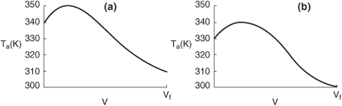
We see from Figure 12-5(a) that our guess of 340 K for Ta2 at the feed entrance (V = 0 and X = 0) gives an entering temperature of the coolant of 310 K (V = Vf), which does not match the actual entering coolant temperature of 300 K.
- Now guess a coolant temperature at V = 0 and X = 0 of 330 K. We see from Figure 12-5(b) that an exit coolant temperature of Ta2 = 330 K will give a coolant temperature at Vf of 300 K, which matches the acutal Ta0.
12.3 Algorithm for PFR/PBR Design with Heat Effects
We now have all the tools to solve reaction engineering problems involving heat effects in PFRs and PBRs for the cases of both constant and variable coolant temperatures.
Table 12-2 gives the algorithm for the design of PFRs and PBRs with heat exchange: In Case A Conversion is reaction variable and in Case B Molar Flow Rates are the reaction variables. The procedure in Case B must be used to analyze multiple reactions with heat effects.
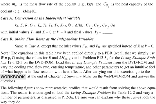
Table 12-2. Algorithm for PFR/PBR Design with Heat Effects