
5.3.2 CSTRs in Series
A first-order reaction with no change in the volumetric flow rate (υ = υ0) is to be carried out in two CSTRs placed in series (Figure 5-5).
Figure 5-5. Two CSTRs in series.

The effluent concentration of reactant A from the first CSTR can be found using Equation (5-9)
![]()
with τ1 = V1/υ0. From a mole balance on reactor 2,
![]()
Solving for CA2, the concentration exiting the second reactor, we obtain
![]()
If both reactors are of equal size (τ1 = τ2 = τ) and operate at the same temperature (k1 = k2 = k), then
![]()
If instead of two CSTRs in series we had n equal-sized CSTRs connected in series (τ1 = τ2 = ··· = τn = τi = (Vi/υ0)) operating at the same temperature (k1 = k2 = ··· = kn = k), the concentration leaving the last reactor would be
![]()
Substituting for CAn in terms of conversion
![]()
and rearranging, the conversion for these identical n tank reactors in series will be
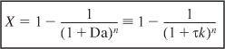
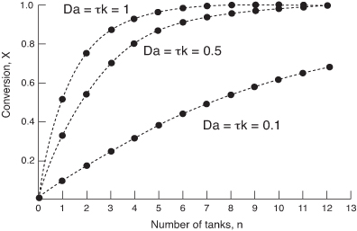
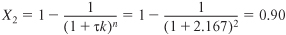
A plot of the conversion as a function of the number of reactors in series for a first-order reaction is shown in Figure 5-6 for various values of the Damköhler number τk. Observe from Figure 5-6 that when the product of the space time and the specific reaction rate is relatively large, say, Da = 1, approximately 90% conversion is achieved in two or three reactors; thus the cost of adding subsequent reactors might not be justified. When the product τk is small, Da ~ 0.1, the conversion continues to increase significantly with each reactor added.
Figure 5-6. Conversion as a function of the number of tanks in series for different Damköhler numbers for a first-order reaction.
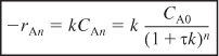
The rate of disappearance of A in the nth reactor is
Example 5-2. Producing 200 Million Pounds per Year in a CSTR
Close to 6 billion pounds of ethylene glycol (EG) were produced in 2007. It previously ranked as the twenty-sixth most produced chemical in the nation on a total pound basis. About one-half of the ethylene glycol is used for antifreeze, while the other half is used in the manufacture of polyesters. In the polyester category, 88% was used for fibers and 12% for the manufacture of bottles and films. The 2000 selling price for ethylene glycol was $0.69 per pound.
It is desired to produce 200 million pounds per year of EG. The reactor is to be operated isothermally. A 16.1 mol/dm3 solution of ethylene oxide (EO) in water is mixed (see Figure E5-2.1) with an equal volumetric solution of water containing 0.9 wt % of the catalyst H2SO4 and fed to the reactor. The specific reaction rate constant is 0.311 min–1, as determined in Example 5-1. Practical guidelines for reactor scale-up are given by Mukesh1.

a. If 80% conversion is to be achieved, determine the necessary CSTR volume.
b. If two 800-gal reactors were arranged in parallel with the feed equally divided, what would be the corresponding conversion?
Assumption: Ethylene glycol (EG) is the only reaction product formed.
The specified Ethylene Glycol (EG) production rate in mol/s is
![]()
From the reaction stoichiometry
FC = FA0X
we find the required molar flow rate of ethylene oxide for 80% conversion to be
![]()
a. We now calculate the single CSTR volume to achieve 80% conversion using the CRE algorithm.
- CSTR Mole Balance:
E5-2.1

- Rate Law:
E5-2.2


- Stoichiometry. Liquid phase (υ = υ0):
E5-2.3
- Combining:
E5-2.4

- Evaluate:
The entering volumetric flow rate of stream A, with CA01 = 16.1 mol/dm3 before mixing, is
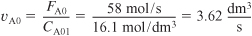
From the problem statement υB0 = υA0

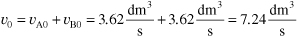
The total entering volumetric flow rate of liquid is
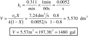
Substituting in Equation (E5-2.4), recalling that k = 0.311 min–1, yields

b. CSTRs in parallel. For two 800-gal CSTRs arranged in parallel (as shown in Figure E5-2.2) with 3.62 dm3/s (υ0/2) fed to each reactor, the conversion achieved can be calculated by rearranging Equation (E5-2.4)

to obtain

where

Figure E5-2.2. CSTRs in parallel.

Da = τk = 836.5s×0.0052s-1 = 4.35
Substituting into Equation (E5-2.5) gives us

The conversion exiting each of the CSTRs in parallel is 81%.
Problem P5-2(b) asks you to generalize the result for n equal size rectors Vi in parallel with equal feed rates (FA0/n) and show that the conversion would also be the same if everything were fed to one big reactor of volume V = nVi
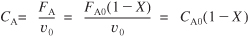
c. CSTRs in series. If the 800-gal reactors are arranged in series, the conversion in the first reactor [cf. Equation (E5-2.5)] is

where
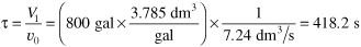
The Damköhler number is
To calculate the conversion exiting the second reactor, we recall that V1 = V2 = V and υ01 = υ02 = υ0; then
τ1 = τ2 = τ
Conversion in the series arrangement is greater than in parallel for CSTRs. From our discussion of reactor staging in Chapter 2, we could have predicted that the series arrangement would have given the higher conversion.
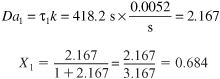
Figure E5-2.3. CSTRs in series.
A mole balance on the second reactor is

Basing the conversion on the total number of moles reacted up to a point per mole of A fed to the first reactor,
FA1 = FA0 (1 – X1) and FA2 = FA0 (1 – X2)
Rearranging
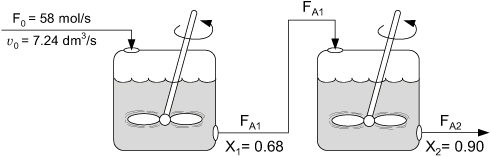
Combining the mole balance on the second reactor [cf. Equation (2-24)] with the rate law, we obtain
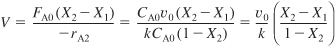
Solving for the conversion exiting the second reactor yields

The same result could have been obtained from Equation (5-15):
Over two hundred million pounds of EG per year can be produced using two 800-gal (3.0-m3) reactors in series.
Analysis: The CRE algorithm was applied to a first-order-irreversible-liquid phase reaction carried out isothermally in a single CSTR, 2 CSTRs in series, and also 2 CSTRs in parallel. The equations were solved algebraically for each case. When the entering molar flow rate was equally divided between the 2 CSTRs in parallel, the overall conversion was the same as that for a single CSTR. For two CSTRs in series, the overall conversion was greater than that of a single CSTR. This result will always be the case for isothermal reactions with power law rate laws with reaction orders greater than zero.
We can find information about the safety of ethylene glycol and other chemicals from the World Wide Web (WWW) (Table 5-4). One source is the Vermont Safety Information Resources, Inc. Web site (Vermont SIRI, www.siri.org). For example, we can learn from the Control Measures that we should use neoprene gloves when handling the material, and that we should avoid breathing the vapors. If we click on “Dow Chemical USA” and scroll the Reactivity Data, we would find that ethylene glycol will ignite in air at 413°C.
Table 5-4. Accessing Safety Information

5.4 Tubular Reactors
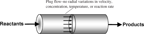
Gas-phase reactions are carried out primarily in tubular reactors where the flow is generally turbulent. By assuming that there is no dispersion and there are no radial gradients in either temperature, velocity, concentration, or reaction rate, we can model the flow in the reactor as plug-flow.2
Figure 1-9. (Revisited) Tubular reactor.
The differential form of the PFR design equation
![]()
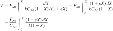
must be used when there is a pressure drop in the reactor or heat exchange between the PFR and the surroundings. In the absence of pressure drop or heat exchange, the integral form of the plug-flow design equation is used,

As an example, consider the elementary reaction
![]()
for which the rate law is
![]()
We shall first consider the reaction to take place as a liquid-phase reaction and then as a gas-phase reaction.
Liquid Phase υ = υ0
The combined PFR mole balance and rate law is
![]()
If the reaction is carried out in the liquid phase, the concentration of A is
CA = CA0 (1 – X)
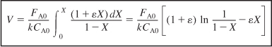
and for isothermal operation, we can bring k outside the integral
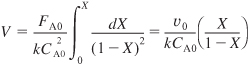
This equation gives the reactor volume to achieve a conversion X. Dividing by υ0 (τ = V/υ0) and solving for conversion, we find
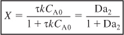
where Da2 is the Damköhler number for a second-order reaction, i.e. τkCA0.
![]()
For constant-temperature (T = T0) and constant-pressure (P = P0) gas-phase reactions, the concentration is expressed as a function of conversion:
![]()
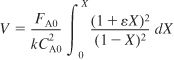
and then combining the PFR mole balance, rate law, and stoichiometry

The entering concentration CA0 can be taken outside the integral sign since it is not a function of conversion. Because the reaction is carried out isothermally, the specific reaction rate constant, k, can also be taken outside the integral sign.
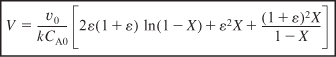
From the integral equations in Appendix A.1, we find that
Effect of ε on Conversion
We now look at the effect of the change in the number of moles in the gas phase on the relationship between conversion and volume. For constant temperature and pressure, Equation (4-23) becomes
υ = υ0 (1 + εX)
Let’s now consider three types of reactions, one in which ε = 0 (δ = 0), one in which ε < 0 (δ < 0), and one in which ε > 0 (δ > 0). When there is no change in the number of moles with reaction, (e.g., A → B) δ = 0 and ε = 0; then the fluid moves through the reactor at a constant volumetric flow rate (υ = υ0) as the conversion increases.
When there is a decrease in the number of moles (δ < 0, ε < 0) in the gas phase, the volumetric gas flow rate decreases and the conversion increases. For example, when pure A enters for the reaction 2A → B, then taking A as the basis of calculation, then A → B/2 and we have: ![]()
υ = υ0(1 – 0.5X)
Consequently, the gas molecules will spend more time in the reactor than they would if the flow rate were constant, υ = υ0. As a result, this longer residence time would result in a higher conversion than if the flow were constant at υ0.
On the other hand, if there is an increase in the total number of moles (δ > 0, ε > 0) in the gas phase, then the volumetric flow rate will increase as the conversion increases. For example, for the reaction A → 2B, then ε = yA0δ = 1(2 – 1)=1
and the molecules will spend less time in the reactor than they would if the volumetric flow rate were constant. As a result of this smaller residence time in the reactor, the conversion will be less than what would result if the volumetric flow rate were constant at υ0.
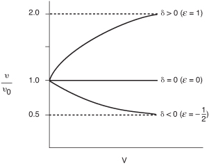
Figure 5-7 shows the volumetric flow rate profiles for the three cases just discussed. We note that, at the end of the reactor, virtually complete conversion has been achieved.
Figure 5-7. Change in gas-phase volumetric flow rate down the length of the reactor.
Example 5-3. Producing 300 Million Pounds per Year of Ethylene in a Plug-Flow Reactor: Design of a Full-Scale Tubular Reactor
Ethylene ranks first in the United States in total pounds of organic chemicals produced each year, and it is the number one organic chemical produced each year. Over 60 billion pounds were produced in 2010, and it sold for $0.37 per pound. Sixty-five percent of the ethylene produced is used in the manufacture of fabricated plastics, 20% for ethylene oxide, 16% for ethylene dichloride and ethylene glycol, 5% for fibers, and 5% for solvents.
Determine the plug-flow reactor volume necessary to produce 300 million pounds of ethylene a year from cracking a feed stream of pure ethane. The reaction is irreversible and follows an elementary rate law. We want to achieve 80% conversion of ethane, operating the reactor isothermally at 1100 K and at a pressure of 6 atm. The specific reaction rate at 1,000 K is 0.072 s–1 and the activation energy is 82,000 cal/mol.
![]()
Let A = C2H6, B = C2H4, and C = H2. In symbols,
![]()
Because we want the reader to be familiar with both metric units and English units, we will work some of the examples using English units. Trust me, a number of old timers still use concentrations in lb-mol/ft3. To help you relate English and metric units, the corresponding metric units will be given in parenthesis next to the English units. The only step in the algorithm that is different is the evaluation step.
The molar flow rate of ethylene exiting the reactor is

Next, calculate the molar feed rate of ethane, FA0, to produce 0.34 lb mol/s of ethylene when 80% conversion is achieved,

- Plug-flow Mole Balance:

Rearranging and integrating for the case of no pressure drop and isothermal operation yields

- Rate Law:3

The activation energy is 82 kcal/g mol.
- Stoichiometry. For isothermal operation and negligible pressure drop, the concentration of ethane is calculated as follows:
Gas phase, constant T and P:


- Combine Equations (E5-3.1) through (E5-3.3) to obtain
- Evaluate.
Since the reaction is carried out isothermally, we can take k outside the integral sign and use Appendix A.1 to carry out our integration.
- Parameter evaluation:

Oops! The rate constant k is given at 1000 K, and we need to calculate k at reaction conditions, which is 1100 K.
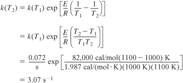
Substituting into Equation (E5-3.6) yields


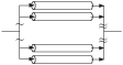
It was decided to use a bank of 2-inch schedule 80 pipes in parallel that are 40 feet in length. For pipe schedule 80, the cross-sectional area, AC, is 0.0205 ft2. The number of pipes necessary is
![]()
To determine the concentrations and conversion profiles down the length of the reactor, z, we divide the volume Equation (E5-3.8) by the cross-sectional area, AC,
![]()
Equation (E5-3.9) was used along with AC = 0.0205 ft2, and Equations (E5-3.8) and (E5-3.3) were used to obtain Figure E5-3.1. Using a bank of 100 pipes will give us the reactor volume necessary to make 300 million pounds per year of ethylene from ethane. The concentration and conversion profiles down any one of the pipes are shown in Figure E5-3.1.
Figure E5-3.1. Conversion and concentration profiles.

Analysis: The CRE algorithm was applied to a gas phase reaction that had a change in the total number of moles during the reaction. A bank of 100 PFRs in parallel each with a volume of 0.81 ft3 will give the same conversion as 1 PFR with a volume of 81 ft3. The conversion and concentration profiles are shown in Figure E5-3.1. You will note that the profiles change more rapidly near the entrance to the reactor where the reactant concentrations are high and changes more slowly near the exit where most of the reactants have been consumed resulting in a smaller rate of reaction.
5.5 Pressure Drop in Reactors
In liquid-phase reactions, the concentration of reactants is insignificantly affected by even relatively large changes in the total pressure. Consequently, we can totally ignore the effect of pressure drop on the rate of reaction when sizing liquid-phase chemical reactors. However, in gas-phase reactions, the concentration of the reacting species is proportional to the total pressure; consequently, proper accounting for the effects of pressure drop on the reaction system can, in many instances, be a key factor in the success or failure of the reactor operation. This fact is especially true in microreactors packed with solid catalyst. Here the channels are so small (see Problem 5-24B) that pressure drop can limit the throughput and conversion for gas-phase reactions.