
Chapter 8. The Host/Controller Interface
The best way to predict the future is to invent it.
—Alan Kay
8.1. Introduction
As shown in Figure 3–1, the Host Controller Interface (HCI) is the interface between the host and the controller. It is responsible for two main functions: It sends commands to the controller and receives events back, and it sends and receives data from a peer device.
Typically, the host interface is both a physical and logical interface between devices. The logical interface defines a number of packet formats for commands, events, and data. The physical interface then defines how these packets can be transported between the host and controller.
8.2. Physical Interfaces
There are four defined physical interfaces in the Bluetooth specification. Each is optimized for a different purpose:
• The Universal Asynchronous Receiver/Transmitter (UART) is optimized for very simple implementations.
• 3-Wire UART is optimized for reliable UART implementations.
• USB is optimized for high speed, typically in computers and similar devices.
• Secure Digital Input Output (SDIO) is optimized for medium speed, typically in consumer electronic devices.
8.2.1. UART
The UART interface is the simplest of all the transports available. It defines a simple universal asynchronous receiver/transmitter that is connected in a null-modem configuration between the host and the controller. Null modem simply means the transmit and receive wires cross over at opposite ends of the link so that transmit data (TXD) from the controller connects to receive data (RXD) on the host, and vice versa. Three-wire UARTS only have TXD, RXD, and ground. Five-Wire UARTS also have flow control wires by which the request to send (RTS) on the controller connects to clear to send (CTS) on the host, and vice versa.
In Bluetooth low energy, the UART interface always uses 8-bit characters with no parity and one stop bit. The stop bit is an extra bit’s worth of time at the end of each byte. The parity bit is used for error checking when used. When the link between Bluetooth controller and host is very short, errors don’t tend to occur and the parity check is not needed. It uses hardware flow control lines CTS and RTS. To send an HCI packet, one of the following three packet type codes is prepended to it. That is it. That’s all it is.
• Command = 0x01
• Data = 0x02
• Event = 0x04
Unfortunately, the UART interface cannot do any low-power signaling, and, therefore, this interface is not suitable for very-low-power devices. Some devices will use additional hardware signaling lines to allow the interface to be moved into a very-low-power mode, but these are typically proprietary extensions and each device will do these extensions differently.
In Bluetooth classic, the HCI packet type of 0x03 is also defined for synchronous data packets; low energy does not use synchronous data packets; thus, they would never be sent to or from a low-energy-only controller.
8.2.2. 3-Wire UART
The 3-wire UART is a little more complex than the previously described UART transport because it is designed to work without any hardware flow control lines as well as in the presence of some bit errors. If your host and controller are separated by more than a few millimeters and they are in a noisy electrical environment, using the 3-wire UART is a strong recommendation.
For the 3-wire UART to work, channels are used in a similar manner to the UART interface described earlier. The channel numbers are the same, with 0x1 for commands, 0x2 for data, and 0x4 for events. The 3-wire UART also defines two additional channels for link establishment on channel 0xF and one for acknowledgements on channel 0x0. Note: Channel numbers in 3-wire UART are only four bits in size.
The 3-Wire UART has three main modes:
• Link establishment
• Active state
• Low-power state
The link establishment channel is used to confirm that the peer device is awake and to configure any parameters. The link establishment channel can also be used for automatic baud-rate detection. It does this by sending link establishment messages at different baud rates and determining which one caused the peer device to respond. The link establishment process is effectively a three-way handshake between the two devices to move them into the normal state. This includes configuration of the reliable sliding window size, whether a cyclic redundancy check (CRC) is used, and if out-of-frame software flow control is used.
In the active state, reliable packets can be sent. All packets are framed and include a sequence number and an acknowledgement number. These numbers are both three bits in size, allowing multiple packets to be in transit at the same time. This is useful for very fast UARTs for which it might take some time to process a packet.
The framing of packets uses SLIP, as defined in RFC 1055. SLIP places a 0xC0 octet at the start and end of every packet to frame it. It then replaces any occurrences of 0xC0 in the packet with a two-octet byte stream of 0xDB 0xDC. Given that 0xDB is an escape sequence, this also needs to be converted into a two-octet byte stream of 0xDB 0xDD. If out-of-frame software flow control is used, the XON and XOFF octets will also be escaped to 0xDB 0xDE and 0xDB 0xDF.
The packet header of a framed packet also includes the length of the packet and a header checksum. The header checksum just validates that the header information can be trusted. If it is invalid, then the entire packet is rejected, and a retransmission scheme will automatically retransmit this packet.
The payload can be up to 4,095 bytes and is protected by a CRC value. The CRC used in the 3-wire UART is the same CRC that is used in the Bluetooth classic baseband packets—the 16-bit CRC-CCITT. Again, if the CRC fails to validate the packet, the packet is just ignored, and the entire packet will be retransmitted by the peer device.
It is also possible to move the connection into low power mode by sending a “sleep” message. In this mode, the UART is typically turned off and any packet that is transmitted is not guaranteed to be fully received; it can take some time for the UART hardware on the peer device to wake up once a packet is transmitted. To aid the efficient wakeup of a peer device before sending HCI messages, a very short wakeup message can be sent. The device responds with a “woken” message, after which, the devices have an active connection and can send any packets.
If a device only has a UART interface, and the basic UART interface isn’t proving robust against bit errors, the 3-wire UART is the right way to go.
8.2.3. USB
The USB interface is optimized for devices that already include a USB host. It defines how to transmit commands and events as well as data between the host and the device. For enumeration, a standard class code for Bluetooth devices is also defined. This has allowed plug-and-play Bluetooth dongles to be sold by many manufacturers.
Commands from the host to a device are sent on the Control endpoint (0x00) using a “host to device class request, device as target” request type. Events are polled from the device by the host using an Interrupt endpoint (0x81). This endpoint should be polled every millisecond to ensure that events can flow with the minimum of latency.
Data is sent on two endpoints: one for Bulk data out (0x02) for data from the host to the device, and one for Bulk data in (0x82) for data from the device to the host. Again, a one-millisecond poll interval is used; however, multiple Bulk data USB packets can be sent in a single frame, allowing for very high data throughput where needed.
The biggest problem with USB is that it is not very power sensitive. To implement a USB interface requires lots of high-speed hardware and software control. This is an expensive proposition. Another problem is that the USB host must poll for data from the device every millisecond. Typically, this stops the host from moving into the lowest-power processor states while the device is being used. This can be solved by another USB featured called Link Power Management. It is recommended to use this on Bluetooth devices.
8.2.4. SDIO
The SDIO protocol is a high-speed interface by which a host can communicate with a controller over the SDIO Card Type-A interface. SDIO is a packet-based bus that uses between 4 and 8 lines to transmit data in both directions very quickly using very little power.
The transport uses the same channel assignments that are used by UART and 3-wire UART transports for commands, events, and data.
The SDIO interface has very low error rates, which makes it very useful for devices that already have an SDIO interface available.
To obtain the full SDIO transport specifications, you must be a member of the SD Association. However, a version of these specifications has been made available to help companies evaluate the technology. These simplified specifications do not include everything that is necessary to build a product, but they do contain enough information to obtain an understanding of how the system works.
8.3. Logical Interface
Above the HCI physical transports is the logical interface. It is a logical interface because in the single-chip device, this interface doesn’t need to be implemented as a message-passing interface between components. For a system in which the controller and host are on separate chips connected by a physical interface, the HCI logical interface is represented as physical packets transferred over this physical interface.
There are three concepts to understand about the logical interface:
• Channels
• Packet formats
• Flow control
8.3.1. HCI Channels
Whenever a controller has a connection to another device, the controller’s lower HCI interface creates an HCI channel that is identified by using a connection handle. This connection handle is used to identify all data that is sent from the host to the controller that is to be sent to a specific peer device as well as all data that is received from that peer device by the controller before it is sent to the host.
The connection handle is given to the host whenever the attempt to create a connection completes. The connection handle is valid until the connection is terminated, either locally, by the Link Layer termination procedure, or due to a link supervision timeout.
8.3.2. Command Packets
To command the controller to do something useful, command packets are sent by the host to the controller. These command packets typically are used to either configure the state of the controller or ask it to do something.
As illustrated in Figure 8–1, the HCI command packet contains an opcode that determines the command that is being sent, a parameter length field, and the parameters for the command. Each command has its own unique set of parameters.

Figure 8–1. The HCI command packet format
There are three basic types of commands in Bluetooth low energy that perform the following functions:
• Configure the controller state
• Request a specific action
• Control a connection
8.3.2.1. Configuring the Controller State
The controller can be considered to be one big state machine that has a number of parameters which can be configured. For example, advertising can be considered to be a state that has the following state that can be configured by using the LE Set Advertising Parameters command, LE Set Advertising Data command, LE Set Scan Response Data command, and the LE Set Advertise Enable command.
Typically, within Bluetooth low energy, the state used within a state machine cannot be changed while that state is being used. Therefore, it is impossible to change the advertising parameters while advertising is enabled. It is therefore necessary to disable advertising, change the advertising parameters, and then enable advertising again.
8.3.2.2. Requesting a Specific Action
Some commands request a specific action to occur without altering the state of the device or the state of a connection. For example, the LE Encrypt command takes a key and some plain-text data and requests the controller to generate some encrypted data based on these.
8.3.2.3. Controlling a Connection
When a connection has been created between two devices, commands can be sent to manage this connection. These commands always include the connection handle. For example, the LE Read Channel Map command is used to read the current adaptive frequency-hopping channel map for a given connection.
8.3.3. Event Packets
Event packets are used to send information from the controller to the host, typically in response to something that the host has previously commanded.
Figure 8–2 shows that the HCI event packet contains an event code that determines which event is being sent, a parameter length field, and the parameters for the event. Each event has its own unique set of parameters.

Figure 8–2. The HCI event packet format
Three basic event types are used in Bluetooth low energy:
• Generic command complete events
• Generic command status events
• Command-specific completion events
8.3.3.1. Generic Command Complete Events
Whenever a command is sent to the controller that can be completed immediately, a generic command complete event is returned. This is the Command Complete event. This event is generic in that the event parameters include the command opcode that this event is completing along with the return parameters that are specified by that command. The first parameter of all command return parameters is a status code that specifies whether the command was successful or had an error and couldn’t complete.
For example, the LE Rand command that is used to command the controller to return a random number has two return parameters: the status code and the requested random number.
The generic command complete event is used whenever the controller can complete a command without doing any over-the-air transactions. For example, the LE Encrypt command does not request any Link Layer packets to be transmitted, so the generic command complete event is used, whereas the LE Create Connection command requires that at a minimum a Link Layer CONNECT_REQ packet is transmitted before the connection is established; therefore, the generic command complete event cannot be used.
8.3.3.2. Generic Command Status Events
For those commands that perform over-the-air transactions, such as creating the connection mentioned in the previous section, a generic command status event is normally followed some time later by a command-specific completion event. The generic command status event is the Command Status event.
8.3.3.3. Command-Specific Completion Events
Some commands require time to complete. These commands always have command-specific completion events. For all of these commands, there is just one command completion event. For example, the LE Create Connection command will first have a Command Status event sent and then an LE Connection Complete event will be sent once the connection is created or the connection fails. It is not until this command-specific completion event is received that the command is considered to be finished.
8.3.4. Data Packets
Data packets are used to send application data from the host to the controller so that it can be transmitted to a peer device, and from the controller to the host that has been received from a peer device.
As illustrated in Figure 8–3, data packets are always labelled with a connection handle. This is a 12-bit value that is provided to the host in the LE Connection Complete event. Until the event is received by the host, it cannot send any data to a peer device. However, once this event is received, the host can start to send data to the peer device, and it will start to receive data from the peer device.
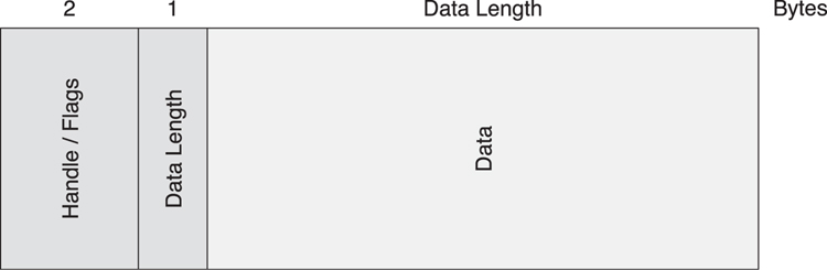
Figure 8–3. The HCI data packet format
There are two flags in the HCI data packet: the Packet Boundary Flag and the Broadcast Flag. Because these packets are reused from Bluetooth classic, some of these flags don’t have any meaning in low energy. The Packet Boundary Flag determines if this packet is a start or continuation of a higher-layer (Logical Link Control and Adaptation Protocol) message. This can be considered to be very similar to the LLID bits in a Data Channel PDU in the Link Layer (for more information, see Chapter 7, The Link Layer, Section 7.8.2).
The interesting thing is that from the host to the controller, this can contain the values 00 (start) and 01 (continuation), whereas from the controller to the host, this can contain the values 10 (start) and 01 (continuation). This is because in Bluetooth classic the value 10 from the host to the controller means that the data packet can be flushed if necessary; with Bluetooth low energy, the concept of flushing doesn’t exist. Instead, it simply drops the link if the data cannot get through, so this value cannot be used. It is for this reason that the value used for the start indication from the host to the controller is 00 (instead of the LLID value 10 at the Link Layer) because this is used for unflushable data in Bluetooth classic.
8.3.5. Command Flow Control
The HCI interface has two forms of flow control: command flow control and data flow control. Command flow control is used to enable the controller to manage how many HCI commands it can process at the same time. The easiest way to consider how this works is to think of the controller as having enough memory to buffer a small number of commands. It communicates the number of these buffers to the host so that the host knows how many commands it can send to the controller at the same time.
There is no event flow control. It is assumed that the number of events that can be sent is limited by the number of commands that can be processed. It is also assumed that the host has more resources than the controller; therefore, it can buffer and process these events in sequence.
To enable command flow control, all Command Complete and Command Status events include a parameter called Num HCI Command Packets. This parameter indicates how many command packets can be buffered in the controller. Each time a command is sent, it uses one of these slots. Each time a Command Complete or Command Status event is sent to the host, it includes the number of slots that are currently free. It is also possible to send a Command Complete event for the opcode “No Operation” with a new Num HCI Command Packets at any time. This is most useful at the initial boot-up of the controller, when it might want to grant the controller more command buffer slots to speed up the initial configuration of the controller by the host.
8.3.6. Data Flow Control
Data flow control is performed in a similar manner. There are two flows of data: host to controller and controller to host. Host to controller data flow control must be used, but the flow control from the controller to the host can be ignored. Most hosts should be able to cope with the quantity of data being sent from the controller to the host, so flow control is not necessary.
For host to controller data flow control, the controller is considered to have a number of buffers, each a fixed size. Each time a data packet is sent from the host to the controller, it uses one of these buffers. Each time a data packet is successfully transmitted by the controller to the peer device, the buffer that held that data packet is released back to the host to fill up with another data packet.
A slight complication with this flow control system is that a dual-mode controller can have two different buffers, one for basic rate data and one for low energy data. This means that there are two HCI commands to discover the buffers on a controller: Read Buffer Size command and LE Read Buffer Size command. Using these two commands, the host can therefore determine which buffers are available. For a low energy–only device, only the LE Read Buffer Size command will return non-zero length buffers.
After the host has discovered the number of buffers available, each time it sends a data packet to the controller, it uses one of these buffers. The buffers are released when a Number Of Completed Packets event is sent from the controller to the host. This has a list of connection handles and the number of packets that was sent. This means that not only does the host know how many buffers have been released but also which data was sent to the peer devices.
8.4. Controller Setup
There are a number of things that the host can do before it attempts to transmit or receive any packets from peer devices. This includes resetting the controller to a known state, reading the device address, setting event masks, reading the flow control buffers, reading the supported features for the local controller, generating a random number, encrypting some data, setting the random address, and configuring white lists.
8.4.1. Reset the Controller to a Known State
It is always useful to reset the controller to a known state before doing anything else (see Figure 8–4). The controller might have been doing something else, and the host transport might only now have been connected. Therefore, resetting should place the controller to the standby state and return all configurable parameters to their default state.
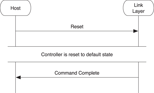
Figure 8–4. HCI reset
To reset the controller, the host sends the Reset command to it. Once the controller has been reset, the Command Complete event for the reset command is sent to the host. It should be noted that this command does not reset the physical transport. If the physical transport needs to be reset, this should be done by using that transport’s reset procedure. It should be further noted that even if the host can send multiple commands, due to command flow control, it is not allowed to send any other commands while the controller is resetting. Any commands that were being processed when the reset is sent will be discarded.
8.4.2. Reading the Device Address
Many low energy devices will have a preprogrammed device address. It is useful for the host to be able to read this address.
To read the device address, the host sends a Read BD_ADDR command to the controller, as shown in Figure 8–5. This causes a Command Complete event to be sent back with the fixed device address. If the controller does not have a fixed address, this address will have the value 00:00:00:00:00:00. The host will then need to generate and program a random address into the controller before it does anything that would cause packets to be transmitted.

Figure 8–5. Reading the device address
8.4.3. Set Event Masks
There are many possible events defined for the controller that can be sent. In the highly likely event that additional functionality is defined in a future version of the specification, there must be a way for the controller to know which events that host is able to receive and process. If the controller just sent every event it knows to the host, but the host doesn’t understand these events, then interoperability problems will occur. The only way to solve this is to allow the host to configure the controller with the set of events that it can accept. The controller will then send only those events.
As demonstrated in Figure 8–6, to set the event masks, two commands are required. First, there is the classic Set Event Mask command that configures the events used by Bluetooth classic. One of these events is the “meta-event” for low energy. It is therefore necessary for the host to enable this meta-event by using this command. Second, the LE Set Event Mask command is used to enable any low energy events that are required.
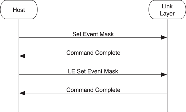
Figure 8–6. HCI set event mask
8.4.4. Read Buffer Sizes
As explained in the data flow control section, the controller has up to two sets of buffers it uses to buffer data that is transmitted from the host to the controller before it is sent to a peer device.
To read the buffers available in the controller, the host sends both the LE Read Buffer Size command and the Read Buffer Size command, as illustrated in Figure 8–7. Once the Command Complete events have been returned, the host can determine how many buffers are available to send low energy data packets to connected devices.
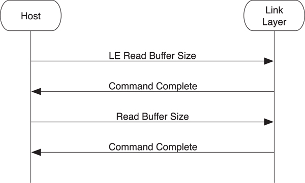
Figure 8–7. Reading the buffer size
8.4.5. Read Supported Features
Another way to ensure that a host can be forward-compatible with a controller is by allowing the host to determine what features a controller supports before sending any feature-specific commands to the controller.
To read the supported features that a controller supports, the host sends the LE Read Supported Features command, as illustrated in Figure 8–8. The controller responds with the Command Complete event, which includes the set of features that this controller supports. This should be sent before any feature-specific commands are sent.

Figure 8–8. Determining what supported features are available on the controller
8.4.6. Read Supported States
The controller can be very simple or it can be very complex. So that a host can scale its operations to the capabilities of the controller without trying possibly invalid combinations of states and receiving back failures, a command is provided that can obtain this information.
To obtain the set of supported state combinations, the host sends the LE Read Supported States command, as depicted in Figure 8–9. The controller responds with a Command Complete event that includes the complete list of possible support states.
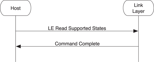
Figure 8–9. Using the LE Read Supported States command
The states that can be supported include the following:
• Nonconnectable advertising
• Scannable advertising
• Connectable advertising
• Directed advertising
• Passive scanning
• Active scanning
• Initiating a connection to the master role
• A connection to the slave role
It also has bits that determine if various combinations of states can be supported, such as the following:
• Nonconnectable advertising and passive scanning at the same time
• Nonconnectable advertising and a connection in the slave role at the same time
With this information, the host can determine whether a given command to start advertising, scanning, or initiating will succeed.
8.4.7. Random Numbers
The controller has a very good source of random numbers. Typically, these random numbers come from some physical property of the device; for example, the phase noise between a free running oscillator and an external crystal time source. As with most random number generators that are based off inherently chaotic physical properties, the number of random numbers that can be generated is limited; therefore, the host should ask for as few random numbers as it possibly can. It can then use these random numbers as seeds into a more classic pseudo-random number generator or by infrequently injecting randomness into such a generator.
To ask the controller to generate a random number, the host sends the LE Rand command. The controller responds with the random number in a Command Complete event, as shown in Figure 8–10.
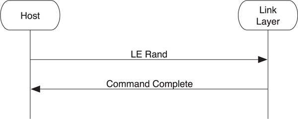
Figure 8–10. Generating random numbers
8.4.8. Encrypting Data
It is sometimes useful for the host to encrypt data by using the AES-128 encryption engine that is used by low energy. Given that the controller has to have implemented this encryption engine, it makes sense to provide access to this engine to the host.
The host can encrypt some plain-text data using an encryption key by sending these pieces of data in an LE Encrypt command to the controller, as illustrated in Figure 8–11. The controller then performs the encryption by using the AES-128 encryption engine and returns the encrypted data in a Command Complete event.
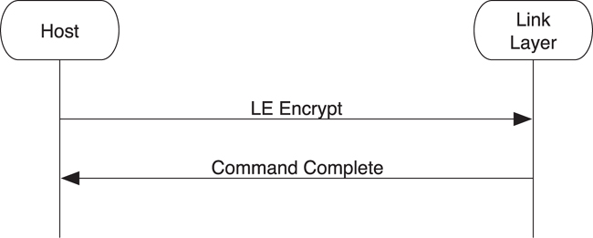
Figure 8–11. The HCI encrypting data
It should be noted that there is no decrypt command. There was a requirement for the host to generate encrypted data for private addresses, but there was no requirement for decrypting data at the host layer. The host can only check that the encrypted data is the same each time something is encrypted and not recover the plain-text data from the encrypted data and an encryption key.
8.4.9. Set Random Address
Some controllers have no fixed device address, or the host wishes to use a private address instead of the fixed address. To accommodate this, the host must program a random address into the controller that can then be used when advertising, active scanning, or initiating connections.
Typically, a random address is generated by using either a random number or a combination of a random number and an identity resolving key. As Figure 8–12 demonstrates, the host requests a good random number from the controller by using the LE Rand command. Next, it uses that as the plain-text data along with its identity resolving key as inputs into the encryption engine by using the LE Encrypt command. The resultant value can then be used to set the random address via the LE Set Random Address command. The random address is available for use by other commands when the Command Complete event is returned.
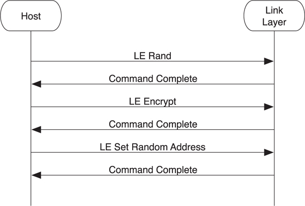
Figure 8–12. Setting a random address
8.4.10. White Lists
The controller has a list of device addresses that can be used for white listing devices. This is especially useful when searching for a few known devices in the fog of advertising packets in busy locations. The white list has a fixed size, so the first thing that needs to be determined is how large this list is. The list can then be managed by using commands to clear, add, and remove devices from this list. The controller can use the list, under the control of the host, to filter advertising packets.
To read the white list size, the LE Read White List Size command is sent by the host to the controller (see Figure 8–13). The controller responds with a Command Complete event that contains the maximum number of entries in its white list. The host can clear all the entries in this list by using the LE Clear White List command. It can also add devices to the white list by using the LE Add Device To White List command. It is also possible to remove a single entry in the white list by using the LE Remove Device From White List command.
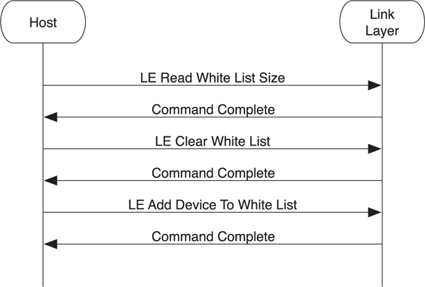
Figure 8–13. Reading a white list
It should be noted that it is not possible to change the contents of the white list while it is being used. For example, if the device is advertising and using the white list to filter the devices to and from which it will respond to scan requests or connection requests, the white list cannot be changed until advertising is disabled. The white list can then be changed and advertising re-enabled.
8.5. Broadcasting and Observing
The most primitive form of communication possible between two Bluetooth low energy devices is the broadcasting and observing model. These use advertising and scanning to transmit and receive data.
8.5.1. Advertising
The controller has two sets of data that can be transmitted by using advertising: advertising data and scan response data. It also has a set of parameters that are used for determining how and when it should transmit advertising packets.
The LE Set Advertising Parameters command allows the host to configure the advertising parameters (see Figure 8–14). This includes the minimum and maximum interval that the host requires the controller to advertise, anywhere from 20 milliseconds to 10.24 seconds. The type of advertising is also specified here. Four types of advertising are available:
• Connectable undirected advertising that is used for general advertising of the advertising and scan response data. This allows any other device to connect to this device.
• Connectable directed advertising that is used to request a particular peer device to connect. This does not include any advertising data.
• Scannable undirected advertising that is used to broadcast advertising data and scan response data to active scanners.
• Nonconnectable undirected advertising that is used to just broadcast advertising data.
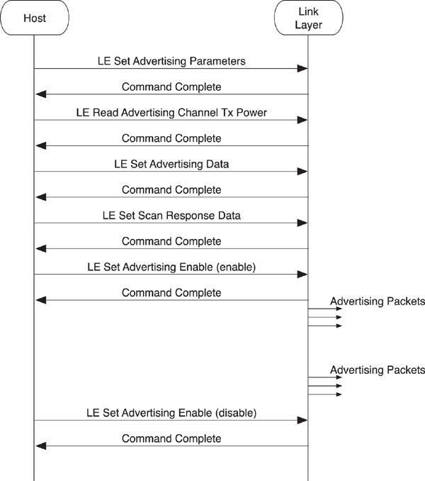
Figure 8–14. HCI advertising
Another parameter of the LE Set Advertising Parameters command is the address type to be used in the advertising data. This can either be the fixed device address or the random address just described. If the type of advertising used is directed advertising, the peer device address is also included. The final two parameters are the advertising channel map that is used to determine which of the three advertising channels should be used and the advertising filter policy. The filter policy determines if the white list is used to help filter out advertising packets that are received in response to an advertising packet. This can be set to one of the following states:
• Allow a scan request or connect request from any device.
• Allow a scan request only from devices in the white list, but allow connect requests from any device.
• Allow a scan request from any device, but only allow connect requests from devices in the white list.
• Allow only scan requests and connect requests from devices in the white list.
The next command that can be sent is the LE Read Advertising Channel Tx Power command. This returns the transmit power used when advertising. This is useful because it allows this value to be included in the advertising data or the scan response data to enable proximity pairing, or sorting devices by path loss in a user interface.
The host can then configure the advertising data and scan response data by using the LE Set Advertising Data and the LE Set Scan Response Data commands.
Once everything is configured, advertising can be enabled or disabled by using the LE Set Advertising Enable command. While advertising is enabled, the controller advertises by using the configured parameters.
8.5.2. Passive Scanning
To receive advertising data from peer devices, you can use passive scanning.
As illustrated in Figure 8–15, the LE Set Scan Parameters command is used to configure the controller’s scanning parameters. These parameters include the scanning filter policy as well as the following:
• Scan type—Either passive scanning or active scanning
• Scan interval—How often the controller should scan
• Scan window—How long the controller should scan for each scan interval
• Scanning filter policy—Accept all advertising packets or only those in the white list
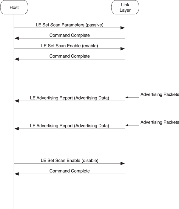
Figure 8–15. HCI passive scanning
The scan interval and window are recommendations from the host to the controller that determine how often and for how long the controller should scan. The interval divided by window determines the duty cycle for which the controller should scan.
For example, if the interval is 100 milliseconds and the window is 10 milliseconds, then the controller should scan for 10 percent of the time. The slowest practical duty cycle that can still pick up a directed advertising packet directed at the controller is a 3.75-millisecond window every 1 second—a 0.4 percent duty cycle.
It is possible to have the interval and window set to the same value. In this case, the scanning is continuous, with a change of scanning frequency once every interval. For example, setting the default parameters at a 10-millisecond interval and a 10-millisecond window results in a 100 percent duty cycle that changes the scanning channel every 10 milliseconds.
The scanning filter policy determines if the white list is used or not. This can allow either all advertising packets to be received, or only advertising packets from devices in the white list to be processed. It should be noted that directed advertising packets that are not addressed to this device would also be discarded, even if sent from a device in the white list.
Once the scanning parameters have been configured, scanning can be enabled by using the LE Set Scan Enable command. Once scanning, the controller sends events up for any advertising packets received that pass the scanning filter policy and other rules. This advertising data is sent to the host in an LE Advertising Report event. In addition to the device address of the advertiser, this event includes any advertising data that was in the packet and the received signal strength indication of this advertising packet. The signal strength can be combined with the transmit power data included in the advertising packet to determine the path-loss of the signal and hence give an approximation of range.
The host can also end scanning by using the same LE Set Scan Enable command but with a parameter set to disable.
8.5.3. Active Scanning
The next complexity up from passive scanning is active scanning. This is used not only to obtain advertising data from peer devices but also their scan response data if possible.
The commands used to configure and enable active scanning are identical to those for passive scanning. However, because the controller will need to send SCAN_REQ packets to the peer device to obtain the scan response data, these packets need to include a device address. Therefore, you use an additional parameter in the LE Set Scan Parameters command to determine whether these Link Layer packets use the fixed device address or the programmed random address, as illustrated in Figure 8–16.
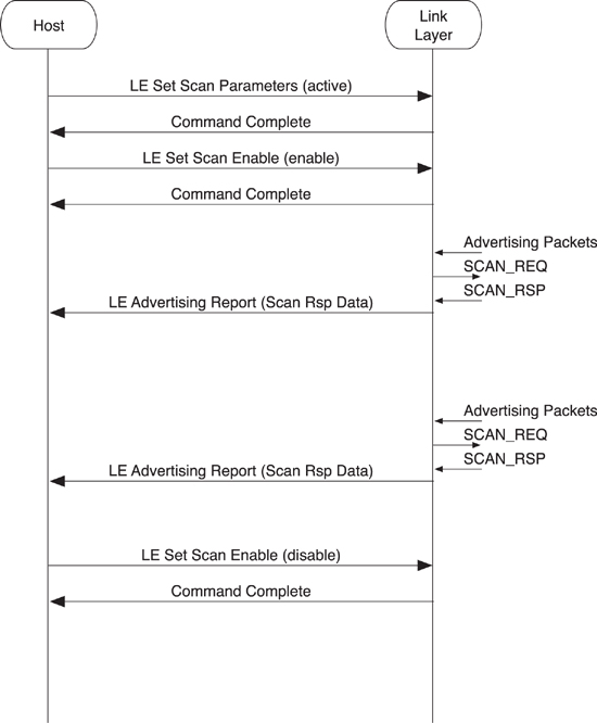
Figure 8–16. HCI active scanning
When the controller receives the SCAN_RSP packets, it sends the same LE Advertising Report event to the host. This event also includes the advertising packet type of the Link Layer packet that caused this event. Thus, it’s possible for the host to distinguish between a peer device that is advertising as connectable or nonconnectable, or whether the device can be scanned, or if this data is advertising data or scan response data.
8.6. Initiating Connections
Advertising and scanning is only useful up to a point. To perform most application work, a connection is required between two devices. To set up a connection, one device must be advertising as connectable, and the other device must be initiating. It is possible to initiate a connection to either a white list or directly to a device. Creating a connection can take some time; therefore, it is useful to be able to cancel the connection creation procedure if the user or application decides that it’s no longer necessary.
8.6.1. Initiating Connection to White List
The most common way to connect to a device is for the host to add the device to the white list and then initiate a connection to the white list. By doing this, a controller can initiate a connection to many devices at the same time. Effectively, this allows a host to ask the controller to initiate a connection to device A, B, C, D, E, F, and so on, all at the same time.
To initiate a connection to one or more devices in the white list, the white list must include that device. As depicted in Figure 8–17, the host uses the LE Add Device To White List and other white list management commands to do this. Once the host is happy with the set of device addresses in the white list, it sends the LE Create Connection command to the controller.
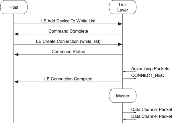
Figure 8–17. HCI initiating a connection to a white list
The LE Create Connection command includes a number of parameters, including the following:
• Scan interval and scan window—Just as with the passive scanning parameters, these determine how often the controller should listen for advertising packets from devices.
• Initiator filter policy—This should be set to “use white list” to initiate a connection to any device in the white list.
• Initiating address type—This determines whether the fixed device address or random address is used in the CONNECT_REQ packet.
• Initial connection parameters—This is used to determine how often the master transmits to the slave and the latency that the slave is allowed to use by ignoring the master, as well as the supervision timeout and the expected quantity of data that is to be sent to or from the slave at each connection interval
It should be noted that the initial connection parameters will be identical for each device in the white list. This command is therefore very useful when connecting to lots of similar devices—for example, automation sensors—but not that useful when connecting to many diverse types of devices. For those circumstances, the host should use the worst-case connection parameters in the LE Create Connection command.
If an advertising packet is received from a device that is in the white list, and this advertising packet is a connectable advertising packet type, the controller will send the CONNECT_REQ packet with all the information required and then generate the LE Connection Complete event. The peer device will also send the LE Connection Complete event up to its host once it receives the CONNECT_REQ packet.
The LE Connection Complete event includes the connection handle that is used to label data packets sent from the host to the controller and the controller to the host for this connection. This event also includes the current role of this controller (either master or slave). It is possible for a device to be advertising as connectable and initiating a connection at the same time; this is useful to determine which one of these succeeded. The event also includes the peer device address as well as the interval, latency, and supervision timeout connection parameters. Finally, the event includes the master’s clock accuracy that is needed to determine how much window widening is required on a slave device. This parameter is provided to the host for informational purposes only.
The other side effect of sending the LE Connection Complete event from the controller to the host is that any advertising or initiating that was ongoing while the connection was being created automatically stops. Therefore, if the host wants to initiate connections to other devices or continue advertising, it must issue new commands to the controller to do so.
8.6.2. Initiating a Connection to a Device
It is also possible to initiate a connection to a single specific device.
To initiate a connection with a single device, the host uses the same LE Create Connection command, as demonstrated in Figure 8–18. However, the initiator filter policy is set to ignore the white list, and other parameters are used to define the device address of the peer device to which it is connecting. Apart from these minor differences, the connection procedure is the same as when initiating to a white list; an LE Connection Complete event is generated on both devices when the connection has been created.
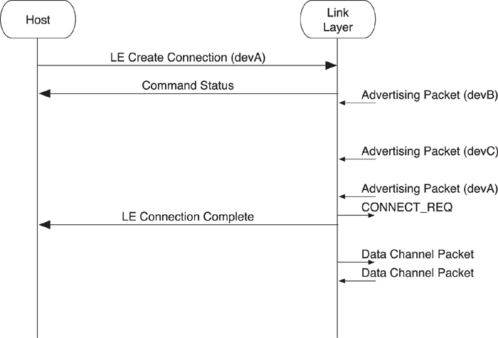
Figure 8–18. HCI initiating a connection to a device
8.6.3. Canceling Initiating a Connection
Sometimes a connection is initiated to a device that is not responding, probably because it is nowhere near the initiating device, and the host wants to cancel this connection request to do something else.
In this example, which is shown in Figure 8–19, the host uses the LE Create Connection command to attempt to connect to a specific device. This also works for initiating a connection to a white list. When the host wants to cancel the initiating of this connection, it sends an LE Create Connection Cancel command to the controller that responds with a Command Complete event for the cancel command as well as an LE Connection Complete event for the initial LE Create Connection command. It is important to complete all commands, and the LE Create Connection command is completed with the LE Connection Complete event, regardless of whether the connection was created.
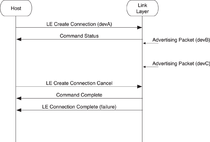
Figure 8–19. Canceling a connection initiation
It should be noted that there is a race condition here. It is possible for the host to send the LE Create Connection Cancel command to the controller at approximately the same time that the controller sends a CONNECT_REQ packet to the peer device but before the LE Connection Complete event is sent to the host to notify it of the new connection. In this condition, the LE Create Connection Cancel command will be completed by using the Command Complete event, but the LE Connection Complete event will be sent up to the host reporting the new connection that has been created. It is possible, therefore, to have created a valid connection even when trying to cancel this very same connection.
8.7. Connection Management
Once a connection has been created, devices can start to manage that connection to lower power consumption, increase or decrease latency, start encryption, or ultimately terminate the connection.
8.7.1. Connection Update
If the connection parameters that are currently being used on a given connection are no longer useful, the host of the master can change the connection parameters. This could be because the connection was initially created with a very fast connection interval to help the devices initially configure themselves, but once the services are in use, a much longer connection interval is much more beneficial to save power.
The master can change the connection parameters by using the LE Connection Update command, as shown in Figure 8–20. This includes the requested new values for the connection interval and connection latency as well as the supervision timeout and new expected connection event length.

Figure 8–20. Changing the connection parameters
The controller responds with a Command Status event before sending a Link Layer connection update request packet to the peer device (for more information on this, go to Chapter 7, Section 7.10.1). This packet includes the timing of an instant when these new connection parameters will take place. Once this instant passes, the new connection parameters are used, and the LE Connection Update Complete event notifies the host that the new connection parameters have been updated.
8.7.2. Channel Map Update
The host might have information about the local channel usage and wish to communicate this information to the controller. For example, it might be co-located with a Wi-Fi radio that is connected to an access point on a given channel and therefore communicating that the low energy channels in the same part of the band would reduce the possibility of the two radios from directly interfering with one another.
There is no way to directly instruct the controller to send a Link Layer channel map request to the peer (for more information about this, go to Chapter 7, Section 7.10.2). However, the host can send the LE Set Host Channel Classification command to the controller, as illustrated in Figure 8–21. This includes a bit field that denotes each Link Layer data channel as either bad or unknown. It is obviously not possible to denote a data channel as good from the point of view of the host because the controller might be measuring the packet error rates by channel already and noticed that some channels denoted as unknown by the host are actually bad.

Figure 8–21. Updating the channel map
The LE Set Host Channel Classification command causes a Command Complete event to be immediately sent to the host. The controller can use the Link Layer control procedures to change the channel map at any time it wants. It is possible for the host to monitor the channel map on a given connection by using the LE Read Channel Map command. This command returns whether each Link Layer data channel is used or unused at this time.
8.7.3. Feature Exchange
It is possible for the host to discover the features that are available on a connection. For example, even if the local controller supports encryption, encryption can only be used if the peer controller also supports it.
Figure 8–22 shows how the master’s host can ask for the remote used features by sending the LE Read Remote Used Features command. This causes a Command Status event to be returned, and the Link Layer feature request (LL_FEATURE_REQ) and response (LL_FEATURE_RSP) to be exchanged (for more information about this, go to Chapter 7, Section 7.10.6). The controller then sends the feature response Link Layer message information to the host in the LE Read Remote Used Features Complete event.

Figure 8–22. Exposing connection features
8.7.4. Version Exchange
When debugging devices, especially those that you do not directly control, it is sometimes useful to find the Link layer version information. This information can then be used to help contact the company that manufactured this device so that you can fix the problem. This information can be requested by either the master or slave host, allowing both devices to debug the link if necessary.
To exchange the version information, the host sends the LE Read Remote Version Information command to the controller, as shown in Figure 8–23. The controller responds with a Command Status event and starts the Link Layer version exchange (for more information about this, go to Chapter 7, Section 7.10.5).
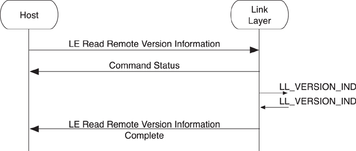
Figure 8–23. Obtaining version information
Once the version information has been exchanged, the controller sends the LE Read Remote Version Information Complete event to the host with the peer device’s version information.
Note that if the LE Read Remote Version Information command is sent a second time, the same sequence of events is returned, but no Link Layer procedure will be performed because the version information is static information and is cached in the controller. This is also true if the remote device has already exchanged version information before the local host sent the command to the controller. Because the controller already has the version information from the remote device, it immediately sends the completion event after the status event.
8.7.5. Starting Encryption
It is possible for the host to enable the encryption of data packets while in a connection, as long as both sides have a shared secret. This shared secret is set up by the Security Manager, either during the initial paring process or through key distribution during bonding.
Two sequences of commands and events must be considered: one from the master’s point of view and one from the slave’s point of view.
The master’s host can ask for the Link Layer to start encryption by sending the LE Start Encryption command that includes the key used to encrypt the connection (see Figure 8–24). The controller returns a Command Status event while encryption is started. The Link Layer then starts encryption (for more information about this, go to Chapter 7, Section 7.10.3). Once encryption has started, the controller sends the Encryption Change event to the master’s host to notify it as to whether encryption is now on or if there was a problem with encryption.

Figure 8–24. HCI master starting encryption
From the point of view of the slave’s host, the sequence of events and commands is slightly different. As depicted in Figure 8–25, the first event that warns the slave’s host that encryption is being enabled is the LE Long Term Key Request event. This event needs to be responded to, by the host, by sending the LE Long Term Key Request Reply command that includes the key to be used for encrypting the connection. Because this is a command, a Command Complete event is used to complete it. After the connection is encrypted, the Encryption Change event is sent to the slave’s host to notify it of the new encryption state.
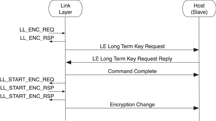
Figure 8–25. HCI slave starting encryption
8.7.6. Restarting Encryption
Sometimes, it is necessary for the host to restart encryption, either by using a new encryption key or just to refresh the initialization vector that is generated as part of the starting of encryption.
As is illustrated in Figure 8–26, from the point of view of the master’s host, the sequence of commands and events are identical to the starting of encryption. The Link Layer has to send more packets, first to pause encryption and then to restart it.
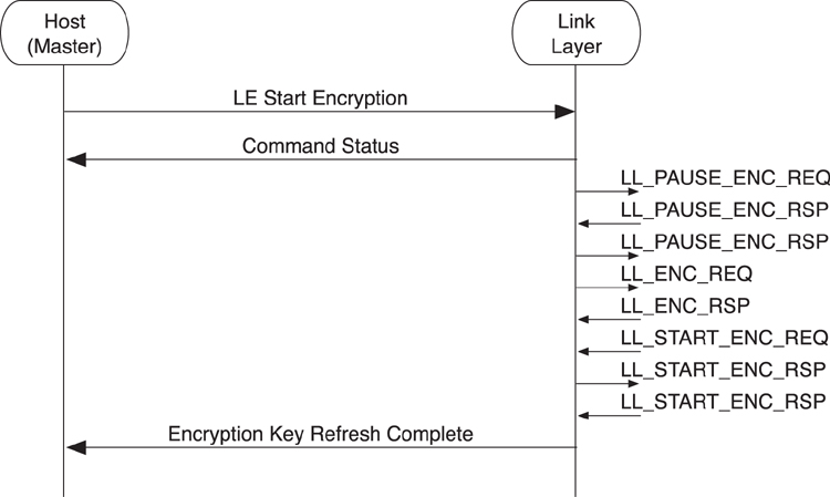
Figure 8–26. HCI master restarting encryption
From the point of view of the slave’s host, the events and commands are also identical, as shown in Figure 8–27.
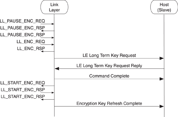
Figure 8–27. HCI Slave Restarting Encryption
It should be noted that it is not possible to turn off encryption in low energy and then send application or host data. Therefore, it is not necessary to send an Encryption Key Refresh Complete as soon as encryption is paused.
This is because of a problem discovered in early versions of Bluetooth classic. Hosts that desired maximum security would try to refresh keys regularly to make them more difficult to crack. However, refreshing keys required turning off encryption, but while encryption was off, data could still be sent. The host couldn’t get around this by simply pausing its flow of data to the controller because there might be data in the controller’s buffers awaiting transmission. This meant that in early versions of Bluetooth classic, hosts trying to increase security ended up actually decreasing security and causing the controller to send unencrypted data. This was fixed in a later version of Bluetooth classic.
Once a host has requested encryption on a connection, there is usually no reason to disable it. So when encryption is paused, data transmission is also paused, closing the security hole that existed in early Bluetooth specifications.
8.7.7. Terminating a Connection
Once either host has decided that no more data needs to be sent on a connection, or if maintaining the connection would use more power than disconnecting and reconnecting at a later time, then the host can terminate the connection.
To terminate the link, the host sends a Disconnect command to the Link Layer, as shown in Figure 8–28. The Link Layer responds with a Command Status and then attempts to terminate the link by using the Link Layer procedures, as defined in Chapter 7, Section 7.10.7. Once the link is terminated, the controller sends the Disconnect Complete event to the host.
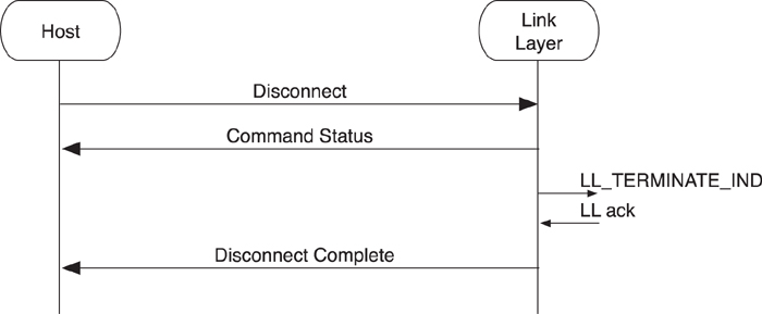
Figure 8–28. Terminating the connection
Is it also possible for the host to receive the Disconnect Complete event at any time when the link terminates due to a supervision timeout or due to an encrypted message integrity check failure. Supervision timeout typically occurs when two devices have moved so far apart from one another that they can no longer receive Link Layer packets from the peer device. Encrypted message integrity check failures should never occur, except when an attacker is attempting to take over a connection, or in very exceptional cases when a very rare pattern of bit errors passes the cyclic redundancy check but fails the message integrity check.