
Chapter 4. The System Context
My context: my conscious mind, connecting me with the multiverse.
In the first chapter, which introduced the case study, I stated that setting the context is key; it helps bring focus to the task at hand. Metaphorically speaking, it is critical that any IT System knows its surroundings, particularly the systems and users with which it is expected to interact in its daily life and the specific languages it needs to speak to communicate effectively and to exchange relevant information with the external systems.
In tech speak, establishing the context in which an application or system will be developed is an important early step toward gaining a good understanding of the interaction and relationships that the evolving system or application will have with its environment (that is, the users and other systems). This insight assists the architect in gaining an understanding of how the system is going to coexist and interact with other entities that are outside the boundary of the application under development.
This chapter focuses on the System Context of an IT System. The System Context provides a catalog of systems (external to the system under consideration), the information flow with the external systems, the external events that the IT System needs to be aware of or respond to, along with a catalog of profiles of different types of user roles that will be accessing and interacting with the IT System to harness its capabilities. For flexibility, I use the terms IT System and system interchangeably.
The Business Context Versus System Context Conundrum
A common discussion point arises around the scope of what should constitute a System Context definition. Finding it difficult to decide where to draw the boundary is quite common: should only the entities within the enterprise be considered, or can entities in other participating organizations also be considered? This is a classic problem that manifests itself in an inconsistent representation of the application’s System Context.
Any entity that resides outside the enterprise perimeter falls, to begin with, under the purview of what is termed as the “Business Context” of a system under construction. The Business Context provides a big picture understanding of interenterprise relationships in relation to interaction between user communities and information exchange. The Business Context consists of one or more diagrams that depict the boundary of the enterprise. Typical examples of Business Context entities are consumers, suppliers, clearinghouses, regulatory bodies, external service providers such as credit card merchandisers, and so on.
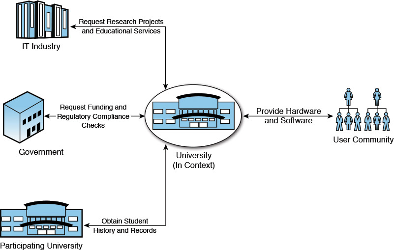
Let’s look at another explanation for the Business Context. The Business Context provides an organizational-level view of how enterprises and organizations are related to each other, supplemented by the type of information exchange, between the organizations, that may be required. IT System designs benefit from leveraging the Business Context diagrams to determine an initial understanding of the percentage split between intersystem communication that lies within the enterprise and the communication that lies outside the enterprise. This understanding is particularly important while building systems that have a substantial amount of dependency on external organizations. The Business Context does not differentiate between the various users and roles but depicts them as a “user community” that interacts with the business. Say you are building particular software for a university. In this case, the Business Context may depict the university as a central entity and represent dependencies on the government, to request for funding and to obtain and perform regulatory conformance checks; on the IT industry, to request for research projects and educational services; on the user community, to which the university will provide hardware and software support; and on other universities in the consortium to obtain student history and records. Figure 4.1 gives a diagrammatic representation of the example.
Although understanding the Business Context may be essential to developing a system that is properly positioned to support the business, it is important to realize and remember that the Business Context diagram does not represent the application or system that is under consideration. Moreover, a Business Context diagram is not necessarily an IT artifact.
Within the System Context, on the other hand, the IT System is brought into focus and relevance. The System Context leverages the Business Context to identify the external organizations. Once the organizational dependencies to build the IT System are identified, the System Context focuses on identifying the specific IT Systems and applications within each of the dependent organizations with which the IT System needs to interact and communicate. Upon its completion, a system-level view can be formed that represents the relevant external systems that need to be brought in scope of the overall solution. Hence, the System Context not only provides a breakdown of the Business Context but a traceability between Business Context constructs (for example, user community and organizations) and the System Context constructs (for example, user roles and systems within organizations) with the business context information. It is important to recognize that “external” does not necessarily imply systems that are outside the enterprise perimeter. Any entity (system or user) inside or outside the organization perimeter is considered external to the system under construction.
Capturing the System Context
As a practical software architect, you must focus on the work at hand. You must agree on, identify, and then analyze the essential artifacts that need to be captured for the System Context. Documenting your understanding of the System Context becomes your top priority.
The first and foremost task in capturing the System Context is to come up with a System Context diagram. The System Context diagram represents the system to be built as a black box (that is, its internal structure and design is hidden), depicts its interaction with external entities (systems and end users), and identifies the information and control flows between the system and the external entities. Keep in mind that external entities need not necessarily be systems that are outside the enterprise perimeter; an existing enterprise application or a database can very well be represented as an external entity in the System Context.
Two essential aspects of the system should be captured:
• The System Context diagram
• The information flows
You may certainly come up with a few more related aspects to capture, but then again, remember that as a practical software architect, you are focusing on just enough!
The following sections focus on artifacts to document and how much of them is enough to be captured; any artifact of relevance when documented may also be called a “work product.”
The System Context Diagram
The best way to understand a System Context diagram is to take a look at an example. Figure 4.2 shows a sample System Context diagram for a fictitious banking solution; I chose banking because it is a commonly known entity.
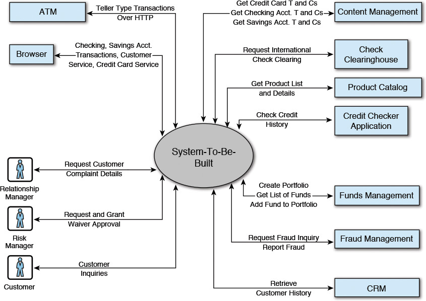
The first category of artifacts is the users (or user profiles) that interact with the system through a set of delivery channels (end-user devices or applications through which users access the IT System). Although there is no hard and fast rule, a common practice in IT is to depict the users, roles, and channels on the left of the diagram. While you are documenting the System Context work product, the recommendation is to create a subsection, under the main section, where the details of the user roles or profiles and the delivery channels may be captured.
Users are usually categorized by the various roles they play in an organization; a set of characteristics and attributes defines their profile. In the real world, however, you may find that user roles and profiles are used interchangeably. In Figure 4.2, the Relationship Manager, Risk Manager, and the Customer are three user roles. The documentation for each of the roles or profiles should have the following information:
• A description of the role and the context in which the users access the system
• A description of the various types of information that the users may request from the system
• The volume of transactions that a typical user, in a given role, would be performing in a given unit of time
The second category of artifacts is the different channels that are used for interaction between the users and the system. Similar to the user profiles, capturing the details of the delivery channels in a separate subsection is recommended. In Figure 4.2, the Browser and the ATM are two delivery channels. The minimum set of artifacts for the delivery channels may include
• A description of the channel along with the types of users who typically use it to interact with the system; for example, browsers, mobile devices, and so on
• The network and bandwidth supported by the channels; for example, T1 line, 802.11a/b/g, modems, and so on
• The access protocol used to send data to and receive it from the system; for example, HTTP, sockets, and so on
The third category of artifacts that must be documented is the external systems with which the IT System needs to interact to fulfill some of its functionality. Typically, a significant amount of analysis of requirements occurs, leading up to the identification of the external systems that need to be brought into the scope of the solution. The results of such analysis warrant sufficient documentation. Following a similar pattern, it is best to dedicate a separate subsection to the documentation of external systems. In Figure 4.2, Content Management, Check Clearinghouse, and all the other systems down to the CRM (that is, the “systems represented” side of the figure—to the right of the System-To-Be-Built) are the external systems. The documentation should minimally capture the following information:
• A descriptive overview of the external system, along with information regarding its proximity to the system to be built. For example, the external system may be inside the enterprise intranet, in the extranet as defined by the business, on the public Internet, or in a different organization’s network.
• The access protocol required to interface with the external system; for example, secure HTTP, sockets, some proprietary access mechanism, and so on.
• The data formats supported or expected by the external system to facilitate integration.
• Any specific compliance requirements that need to be followed to interact with the external system.
• Nonfunctional specifications of the external system; for example, security, availability, information throughput, and so on. Note that you may not need to document all nonfunctional requirements of the external system. Document only those that may influence the architecture and design of the system that needs to be built.
When documented in a commensurate manner, the user profiles, the delivery channels, and the external system details should provide a good illustration of the System Context diagram. However, the information captured so far provides only a static view of the System Context: the user roles and profiles, the information delivery channels, and the external systems. To depict a complete view, the architect would need to understand both the static as well as a dynamic view of the System Context. Identifying and capturing the information that gets exchanged between the system and each of the external systems provides a dynamic view of the System Context. The next section on information flows focuses on addressing the dynamic view.
The Information Flows
Information is everything. Can we ever live without it? If we cannot, why would we deprive our System Context from it? One of the essential tenets of system characterization is defined by the information exchanged between the IT System and the external systems, users, and delivery channels. Information flow can be in batch mode (for example, bulk data transferred in periodic intervals) or in real time (for example, operational and process data as they are generated) or near real time (for example, transactions at a point of sales terminal [POST] in a popular grocery store). Documenting the information and its characteristics, as a part of the System Context, assumes paramount importance when you are defining the overall software architecture.
The information flow is typically represented by a short phrase that can take either a noun or a verb form. Choosing a noun or a verb form is a matter of preference, but whichever you choose, stick with it! I happen to choose the verb form (for example, the Request International Check Clearing information flow between the System-To-Be-Built and the Check Clearinghouse external system in Figure 4.2), but then again, that is a matter of personal choice. Exercise your free will, and choose what you want!
For each information flow, the following minimal set of artifacts may be captured:
• A description of the information that is flowing between the system and the users, the delivery channels, and the external systems
• Classifying the information flow as either batch, real time, or near real time
• The number of transactions that need to be supported per unit of time
• The type of data that constitutes a typical information flow
• The volume of data transferred in each information flow
• The frequency in which each information flow is executed
The artifacts mentioned here do not address the sequence of the interactions between the system and the external entities. When a chain of information flows between two systems, the information flow may also need to document such sequence of interactions.
It’s important to capture the information flow. The reasons that naturally come to mind and are worth noting are as follows:
• The information flow identifies a set of important information entities that will influence the final information model for the software that is going to be built.
• The data formats supported by the external system can be understood by analyzing the information elements. For example, for systems outside the enterprise perimeter, the data format is, more often than not, different from the format that is prescribed to be supported by the IT System. This leads to the identification of data transformation requirements between the two interacting systems.
• The access protocol (network and data) that is used and supported by the external system may be different from the protocol that is agreed upon to be supported by the IT System. The protocol disparity raises technology requirements for application integration. The requirements are usually addressed by the choice of technology adapters. A technology adapter usually normalizes the data format and access protocol differences between the external systems and the IT System. The choice of technology adapters is an important facet of an integration architecture that supports the system that is envisioned to be architected, designed, built, and rolled out.
• The data, protocol, and network adapters are essential recipes that go in the definition of the architecture overview of the system or application. In effect, the heterogeneity of the external systems influences multiple layers of the architecture. (Architecture Overview is covered in the next chapter.)
Business process modeling is a top-down approach to requirements gathering; it is used to analyze and understand the business processes that are in the scope of the business or IT transformation initiative. Process breakdown identifies a set of subprocesses, activities, or tasks that constitute a larger business process. Some of the activities or tasks require interaction or integration with external systems, typically in the form of data dependencies between one system and the other. Such activities can be traced back to one or more information flow definitions that are defined as a part of the portfolio of information flows. This provides a key traceability between the system requirements and their implementation dependency on external systems; such traceability is a fundamental tenet of an efficient and well-organized software development life cycle.
The System Context diagram and its associated information flows, when appropriately captured, provide just enough information for the software architect to start formulating the application architecture.
Case Study: System Context for Elixir
Having developed a good understanding of the areas to address and the artifacts to generate, you should have a template in your head to start capturing the System Context for any system that you are tasked to build.
For our case study, we are trying to architect, design, and build a system for Best West Manufacturers, Inc. The IT System is code-named Elixir. Using the artifacts described in the preceding sections, let’s develop the System Context for Elixir.
Elixir: System Context Diagram
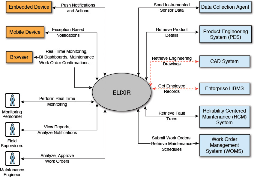
Figure 4.3 depicts the System Context diagram for Elixir. It follows the guidelines stated earlier in this chapter and dedicates separate subsections describing the user profiles, delivery channels, and external systems.
Elixir: User Profiles
Table 4.1 captures the details for a subset of the user profiles for Elixir. The table has four columns: the name of the user profile or role, a description of the role played by the user profile and how the user accesses the system (Elixir, in this case), the information requested by the user profile from the system, and the frequency (along with the volume of information in each request) in which such information requests are made.
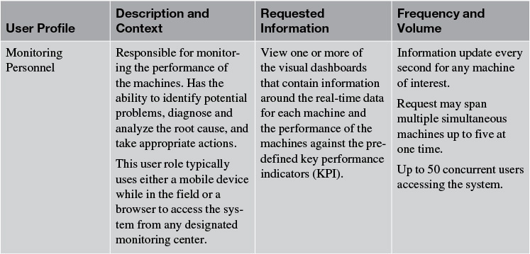
For the sake of readability, I have purposefully refrained from continuing with the table format to capture the complete set of user profile information. In the real world, Table 4.1, appropriately filled in, reads perfectly well in a document format such as Microsoft Word.
The rest of the user profile details for the System Context diagram for Elixir are as follows:
User Profile Name—Field Supervisor
Description and Context—Responsible for analyzing the system’s output related to machine-related exception conditions. The user will get a set of notifications based on exceptions; that is, possible machine conditions that may require attention.
Requested Information—The user requests the system to display the list of machine-related exceptions along with any supporting data (for example, KPI) that she may use to gain more insights into the machine conditions before taking subsequent action.
Frequency and Volume—There could be up to 20 concurrent field supervisors at any given time. The typical user would request to view up to 5 key performance indicators (KPI) at any time. Each KPI data packet may vary anywhere between 250KB to 500KB.
User Profile Name—Maintenance Engineer
Description and Context—Responsible for analyzing maintenance recommendations suggested by the Elixir system. The user is usually notified of outstanding maintenance recommendations in the form of action items in his workbasket. The user analyzes each recommendation in relation to its criticality and the machine’s upcoming maintenance schedule before eventually deciding whether a maintenance order may be dispatched right away or to defer taking action on the system-generated recommendation to the next scheduled maintenance window.
Requested Information—The user requests the system to provide (that is, display) further details regarding the exception conditions that led to the recommendation. The exception details are displayed in the form of a single or composite KPI against which the appropriate business rules were triggered. From the KPI charts, the user can request further details by drilling down to the raw machine data (for example, current, voltage, pressure, temperature, and any relevant values that enable the maintenance engineer to perform additional diagnosis). If, however, the notification was based on a prediction of a future event, instead of an actual occurrence, the user requests the details behind the reason a prediction was made. For example, output of a predictive model stated, with a confidence level of 80 percent, that a specific machine part is predicted to fail in the next 12 hours.
Frequency and Volume—There could be at most 15 concurrent maintenance engineers accessing the system at any given time. The typical user would request to view up to 10 key performance indicators (KPI) at any time. Each KPI data packet may vary anywhere between 250KB to 500KB.
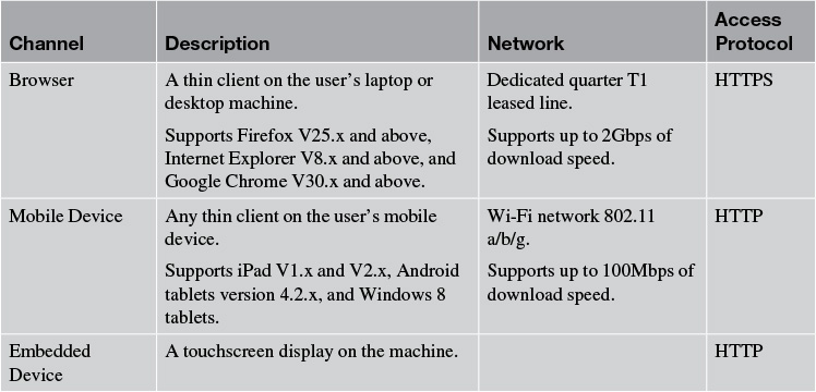
Elixir: Delivery Channels
Table 4.2 captures the details of the delivery channels for Elixir. The delivery channel information, as described earlier in the chapter, focuses on capturing the name of the channel, a brief description of the channel, the type of network used by the delivery channel, and the access protocol used by the network.
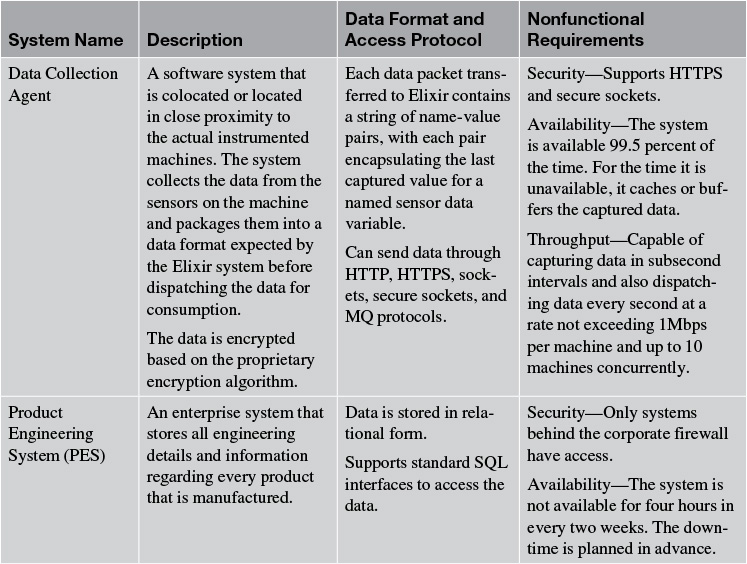
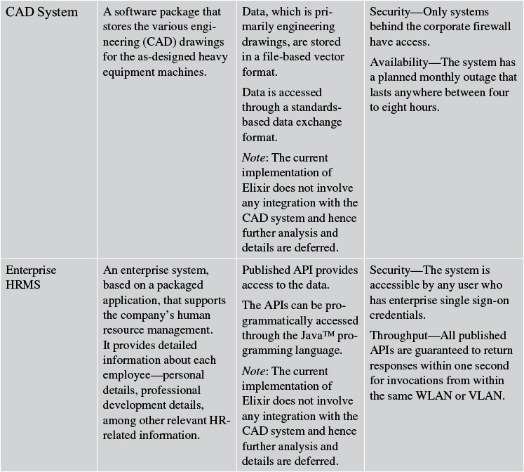
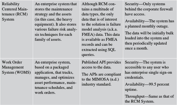
Elixir: External Systems
The Elixir system interfaces and exchanges data with six external systems: the Data Collection Agent, Product Engineering System, CAD System, Enterprise HRMS, Reliability Centered Maintenance System, and Work Order Management System. Table 4.3 captures the details of these external systems; specifically the name of the system, a brief description of the system, details about information exchange, and the nonfunctional requirements that are supported by the system.
Elixir: Information Flows
For the sake of brevity, I have consciously captured only those information flows that occur between Elixir and the four (out of the six) external systems (see Figure 4.3). This is because neither the Enterprise HRMS System nor the CAD System was in the scope of the first release of Elixir. The intent, however, is to capture as much detail of all the information flows as is available at this phase of the architecture definition process (see Table 4.4).
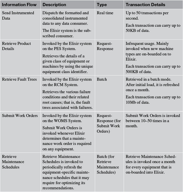
Note that the information flows between Elixir and the Enterprise HRMS System and the CAD System are not shown in Table 4.4. This is because neither of the two external systems is in the scope of the first release of Elixir.
Elixir now has a System Context. The complete artifact documentation may be much more elaborate than what we captured, however.
Summary
This chapter focused on our first real software architecture artifact—the System Context. I articulated the distinction between the Business Context and the System Context and also provided some clues on how they may be related.
The primary emphasis of this chapter was on the System Context artifact and the elements that define and characterize it. The System Context diagram is the first of the two main artifacts of the System Context that I recommend to be captured. The System Context diagram is composed of the user profiles, the delivery channels, and the external systems with which the IT System interacts and interfaces. The second main artifact is the information flows between the external systems and the IT System.
An appropriate level of analysis must be conducted to determine the just enough amount of details, which is commensurate in providing a firm contextual setting based on which the software architecture will be defined.
As an exercise, you can now develop a documentation template to capture the essential artifacts of the System Context. Elixir has a System Context that will form the basis of defining its software architecture. The stage is now set for you to define the software architecture!
References
MIMOSA. (n.d.). The MIMOSA specifications. Retrieved from http://www.mimosa.org/.
Mitra, Tilak. (2008, May 13). Documenting the software architecture, Part 2: Develop the system context. Retrieved from http://www.ibm.com/developerworks/library/ar-archdoc2/.