
Chapter 7. The Functional Model
I function; therefore, I exist.
There was once a clan of architects who strongly believed that their job, as architects, was complete when they provided a comprehensive treatment of the system context, the architecture overview, and the architecture decisions. The rest of the stuff they considered mere design work to be performed by lesser mortals. Take my word for it that times are much harder, my friends, and we need to work much harder and smarter not only to earn our bread but also, if we are passionate enough, to extend the value and reach of architecture and engrain it into much deeper pockets of the software development process.
This chapter demonstrates how to develop and document the macro-level design artifacts of the functional aspects of a system; that is, how the architecture building blocks (ABBs) are deconstructed into design-level constructs that collectively realize the functional requirements of an IT System. Each ABB describes, at a high level, the capabilities of an architecture component in the context of the entire solution. The components not only help in defining the architecture blueprint but also broadly categorize each to be either functional or operational in nature.
This chapter focuses on the functional ABBs of the system and provides guidance and recommendations on how to transform them into macro-level design artifacts—illustrating the various levels of a functional design models through their iterative evolution from higher to lower levels of specificity. It provides prescriptive instruction on how to best articulate and optimally capture the various steps of the functional deconstruction process. And the chapter concludes by instantiating a subset of the functional model for the case study; that is, the Elixir system.
Why We Need It
The functional model is the step that follows the initiation of the architecture decisions in the realization of the system’s architecture. The functional model helps in identifying and defining the following:
• The structure of the IT System
• The dependencies and interactions between a particular set of components of the IT System
• Components that are either specific to the IT System or to a set of technical components that may be leveraged by the IT System
The set of components in the functional model serve a wide variety of purposes. Let’s take a closer look at some of important ones:
Managing system complexity—The functional model follows a process of iterative deconstruction of the ABBs. The technique breaks down a larger system into a set of smaller, more manageable blocks. Each block has a clear set of responsibilities with a well-defined set of interfaces through which it not only realizes its responsibilities but also communicates (that is, collaborates) with other manageable blocks. The manageable blocks are called IT subsystems or just subsystems. You can independently design and implement each subsystem without worrying too much about the rest of the system, thereby managing the complexity of the system design and implementation process. (The book by Jacobson et al. [1999] provides a detailed treatment of UML-based systems design.) The overall functionality of the IT System, supporting the functional use cases, is realized by integrating the subsystems through their well-defined interfaces. The mantra is to divide and conquer (that is, decompose into subsystems) and then integrate back the ‘conquered’ pieces (that is, orchestrating subsystem functionality through their published interfaces in support of all the required use cases) to build your empire!
Establishing the link with the operational model—The functional model evolves by starting from a logical high-level definition to a physical instantiation, following a series of iterative steps. During this iterative process, the physical components are attributed with the nonfunctional parameters that they are expected to honor and support. The component characteristics (defined by their attributions) typically influence and determine the type of deployment units or nodes on which they would be running; that is, operational. The detailed-level specification of the functional model (a.k.a. physical model) enables the integration with the physical operational model. (You learn more about this later in the chapter; I won’t leave you high and dry, I promise!)
Establishing traceability between architecture and design activities and artifacts—The functional model identifies a set of components. The components are a direct derivative of and traceable to the ABBs; as such, they are directly traceable to the system architecture. Moreover, the components are specified at a level of detail that serves as the building blocks that may subsequently be designed and documented for implementation activities. The functional model thus serves as the glue between the system’s architecture and implementation artifacts.
Establishing traceability between requirements and architecture—The functional model explicitly specifies both the functional and nonfunctional capabilities for each of the components. As such, there is a direct traceability to the system requirements.
It is important to acknowledge the value of the functional model as it relates to the overall architecture discipline. My intent is to illustrate the various aspects of the functional model and the techniques to develop and capture the relevant artifacts. Once you acknowledge the value of functional modeling and understand the techniques to develop it, you will be in a position to not only direct the implementation team but also assist the project manager to apportion commensurate time to the design and implementation aspects of the project.
A Few Words on Traceability
It is paramount that any IT construct or artifact must, directly or indirectly, be traceable to some business construct. Being able to trace IT architecture constructs to the business domain assumes paramount importance; ensuring that architecture artifacts (a.k.a. work products) are coherent with and align to the business drivers, goals, and problems that are to be solved. Business analysts analyze the business domain and capture business requirements in a technology-neutral format. They try to capture what needs to be built while leaving how it should be implemented to the IT architects, designers, and implementation team.
Business domain analysis falls under the larger discipline of business architecture, the construction of which involves distinctive techniques and methods that are beyond the current scope of this discussion. However, let me offer a simple example. Component Business Modeling (CBM) is a mechanism used to define business architectures. The CBM matrix (see the “CBM Matrix” sidebar) is defined by a set of business competencies as columns, and accountability levels are rows. The elements in the matrix cell are individual business components that play a specific role within the enterprise ecosystem, collaborating and integrating seamlessly within each other to define and realize the enterprise business processes. (See IBM [2005] for more information on IBM’s CBM method and technique.)
Figure 7.1 shows an example of a typical Component Business Model (CBM) map. This figure is just a diagrammatic reference; if you come across something similar, you will know you are looking at something like a CBM!
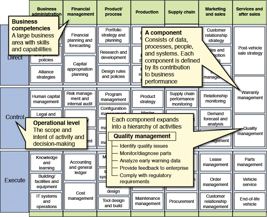
Source: IBM Business Consulting Services and IBM Institute for Business Value.
Figure 7.1 An example of a CBM map. This example is from the automotive industry.
While moving from the business architecture to the IT architecture of an IT System (supporting a whole or part of the business architecture), the business competencies in the CBM model may be used to define a core set of business domains. A business domain may be deconstructed into a set of functional areas. A functional area encapsulates the business processes, subprocesses, and business use cases of a business domain, each one of them being logically cohesive functional units. The functional areas provide a modular view of the business and form the basis of IT subsystem identification, nomenclature, and design. IT subsystem identification and design form the initiation of the functional model. There you go—the traceability is right here!
Developing the Functional Model
The functional model is developed in an iterative manner, enhancing the level of specificity in subsequent iterations, moving from higher levels of abstraction to more specific design and implementation artifacts. The intent is to close the gaps between high-level ABBs and implementation. The three iteration phases I focus on here are the logical-level, specification-level, and physical-level designs. I have found that using these three levels of iterative design is not only the most commonly used but also the most effective technique in developing a functional model for the overall architecture of the system. For the sake of completeness, I’d like to point out a fourth construct that is commonly termed the conceptual-level design; it describes the highest level of abstraction in an evolving functional model.
The four different semantic levels can be briefly summarized as follows:
Conceptual—Described through models that represent the concepts in the domain under consideration. The model elements are technology agnostic (that is, they are not specific to any technology) and deal with real-world entities such as people, processes, and objects, along with their associated attributes.
Logical—Described through a set of artifacts that define a structure of the software system through a set of functionally cohesive constructs called subsystems, each of which encapsulates one or more named components.
Specified—Described through models representing software components (with a detailed level of attribution) that collectively define the specification of the IT System through the interfaces and their externally visible behavior.
Physical—Described through a technology-specific realization of the specified components.
This chapter focuses only on the logical, specified, and physical levels of design because I feel that, from a practical standpoint, they drive more value, and hence focusing on them optimizes the time and effort spent in developing a functional model artifact.
Logical-Level Design
There are two main steps in developing the logical-level view of the functional model. The first step is to identify a set of subsystems (along with a set of identified interfaces for each subsystem) that are typically standalone in nature and collectively depict the behavior of the IT System through a set of well-defined interdependencies between one or more subsystems. The second step is to define the detailed specifications of the each of the components within the subsystems, focusing on their behavior through exposed interfaces and collaborations.
In this chapter, I use a banking scenario for illustrative purposes, choosing banking again because money matters are close to our hearts!
Subsystem Identification
A subsystem is a first-class IT construct and is a direct rendition of the functional areas. The capabilities of a functional area can be represented and realized by one or more IT subsystems. What business functions are to functional areas, IT functions are to IT subsystems: functional areas support business functions, while IT subsystems encapsulate IT functions. Just like functional areas are mapped to and deconstructed into IT subsystems, the business functions are realized by one or more IT functions. These IT functions are logically grouped, encapsulated by, and implemented as a single unit. That unit is the IT subsystem. IT functions are implemented using a collection (that is, one or more) of software components. Hence, a subsystem is a grouping of software components. The IT functions are exposed by a set of interfaces at the subsystem level; each such interface is implemented by a software component inside the subsystem. The subsystem groups the components that are functionally cohesive in nature; changes in the form of enhancements or fixes are hence controlled and their effects localized within a subsystem boundary. The modularization of an IT System into its constituent subsystems fosters parallel development: implementation teams can separately develop the internals of the subsystem while adhering to the external interface contracts.
Identifying the subsystems is typically the first task. Subsystems need to be identified and their definition and characteristics captured. For each subsystem, each of its high-level interfaces also needs to be identified and declared. Adhering to the principles of capturing just enough architecture artifacts, I recommend using a template, like the one shown in Table 7.1, to capture the necessary artifacts for each subsystem.
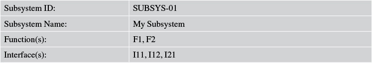
Subsystem ID—Provides a unique ID for each subsystem so that it is easy to identify and also to cross-reference between subsystems.
Subsystem Name—Indicates the name given to a subsystem; for example, Accounts Management, Transaction Management.
Function(s)—Provides a list of IT functions that the subsystem exposes as its behavior. The recommended technique to identify this set is to analyze the system use cases, group them logically, and assign them to the most functionally aligned subsystem.
Interface(s)—Enlists all the interfaces that the subsystem supports or exposes. For example, in an Accounts Management subsystem, an interface may be Withdrawal. At this level, only a textual description of the interface would suffice.
A Unified Modeling Language (UML) representation of the subsystems and their interdependencies may be produced as a part of capturing the design artifacts at the logical level. Figure 7.2 shows an example.
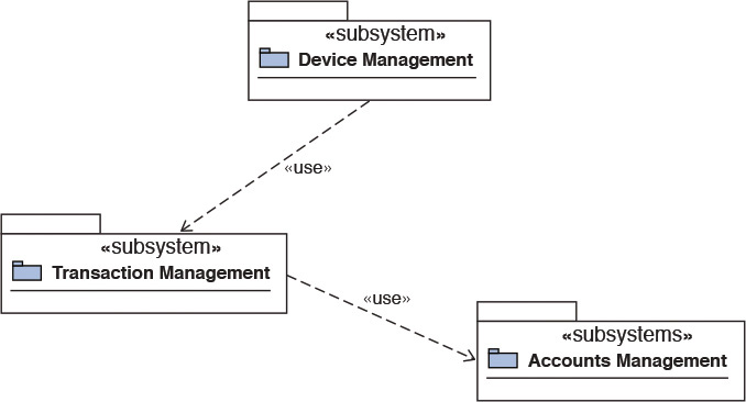
For more details on UML, refer to the UML specifications maintained by the Object Management Group (2011).
Component Identification
Once the subsystems are identified and their responsibilities captured, the next logical step is to identify a set of high-level software components, which collectively realize the interfaces that are exposed by the subsystem. An IT subsystem, as mentioned previously, is a first-class IT manifestation of a functional model. As such, the IT functions within a subsystem can be aligned according to their affinity with a set of core business entities. For example, for the Accounts Management subsystem in Figure 7.2, there might be a couple of software components, one addressing the savings account while the other focuses on implementing the features of the checking account.
So, in this example, there could be two components: namely, Savings Account Manager and Checking Account Manager. The identification of components is not an exact science, and it depends on the designer’s approach toward component granularity. As an example, some designers may choose to identify a single component called Accounts Manager (instead of two; that is, Savings Account Manager and Checking Account Manager) for the Accounts Management subsystem. There is no right or wrong between the two approaches; just keep in mind that the identified components should ideally be intuitive and relevant.
It is important to capture some of the essential details about each of the identified components. Table 7.2 provides a minimal set of details that I recommend capturing.
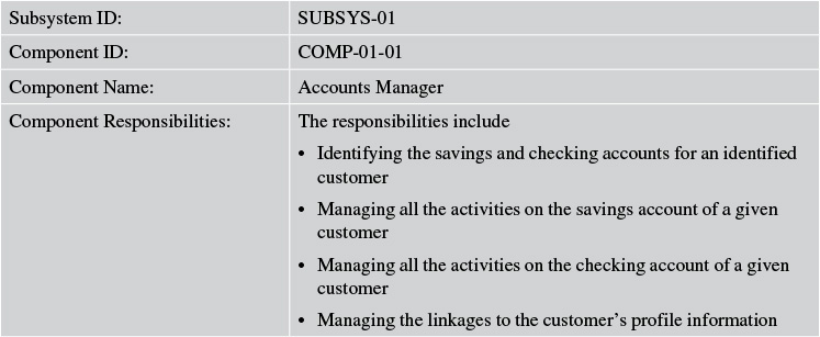
Subsystem ID—Denotes the unique identifier of the subsystem containing the component.
Component ID—Assigns a unique identifier (ID) to the component.
Component Name—Indicates the name given to the component. Ideally, the name should be intuitive based on the business entities that the component may typically manage.
Component Responsibilities—Provides a textual description for the set of responsibilities that are assigned to and are expected (to be implemented) of the component.
Component Interactions
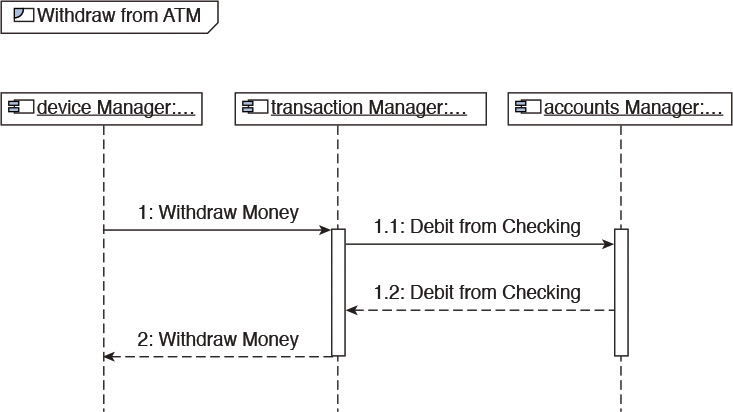
Once the components are identified at a logical level, the next step is to identify the architecturally significant business use cases. The use cases are analyzed, and subsets of them that are significant from an architectural standpoint are chosen. For each of the architecturally significant use cases, component interaction diagrams are used to elaborate how the use case may be realized through a collaborating set of components. A collaboration diagram illustrates how components interact by creating links between the components and by attaching messages to these links. The name of the message denotes the intent of invoking a specific behavior (a.k.a. function) of the invoked component to fulfill a part of the overall use case. Think of the messages as pseudo operations on the components. These pseudo operations manifest themselves as the responsibilities of the component.
Figure 7.3 illustrates a component interaction diagram. The Accounts Manager component and a couple of other components depict how a Withdraw from ATM business use case can be realized at a high level.
To summarize, the three steps—Subsystem Identification, Component Identification, and Component Interaction—are usually adequate to capture the logical-level design of the functional model.
Specified-Level Design
The specified-level design of the functional model focuses on elaborating the detailed behavior of each of the identified components. The logical definitions of the components are used as a starting point and are subsequently expanded to a point that ensures the following:
• The component interfaces are well defined.
• The data elements or entities owned by each subsystem are identified and detailed. (Data entities are aligned with the core business entities of an enterprise, the subset of which is applicable to the IT System being considered.)
• The responsibilities of each component are flushed out in more detail.
I typically recommend following a five-step process for developing the specified-level design for the functional model. The steps could be as follows:
• Component responsibility matrix (detailed)
• Interface specification for components
• Identification and association of data to subsystems
• Component interaction diagram (detailed)
• Assignment of components to layers
Component Responsibility Matrix
This step builds on the initial matrix (see Table 7.1) that was developed during the logical-level design. The existing matrix is enhanced with a more detailed and refined set of component responsibilities.
The existing responsibilities were identified based only on the functional specifications obtained through the analysis of the use cases; the nonfunctional requirements (NFR) of the application were not considered. The nonfunctional requirements are usually captured separately as a part of the requirements-gathering process. Each NFR is analyzed to determine which component or components may need to implement them. The component specification is thus assigned the set of NFRs it will support.
Like NFRs, business rules are typically captured separately in a business rules catalog. Each business rule is analyzed in relation to the functional responsibilities of the components. The outcome of this analysis results in the addition of one or more business rules to the responsibility set of the components. During the implementation phase, a business rules engine is typically selected to implement the collective set of business rules.
For purposes of this example, I assume that you realize how the high-level component responsibilities in the logical-level design are being expanded and elaborated during the specified level of component design.
A snippet of an updated component responsibility matrix is shown in Table 7.3.
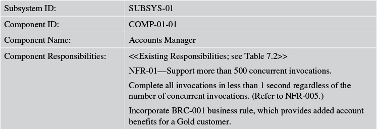
Note: References to NFR-01 and BRC-001 in Table 7.3 are representative examples of documented nonfunctional requirements and a business rule catalog.
Table 7.3 Updated Component Responsibility Matrix—An Illustrative Example
Interface Specification
I introduced the idea of identifying interfaces for subsystems during the logical-level component design. A subsystem is just a logical grouping of components that are functionally cohesive in nature. Hence, the subsystem interfaces, in reality, are interfaces on the components within the subsystem. The components are true physical entities that manifest themselves as executable code.
Now let’s focus on the component interfaces—in particular, their definition and design.
An interface is a software construct through which a component exposes its functionality to the outside world. In technical terms, an interface is a contract described through a collection of operations or methods. Developing the specifications for interfaces primarily deals with the art and science of identifying operations or methods and grouping them within interface boundaries.
To begin with, you should analyze each system use case that is owned by a component, keeping the key factors of complexity and cohesiveness in mind. System use cases that are atomic in nature—for example, Retrieve Customer Profile—should be categorized as operations (on an interface), whereas, for example, a use case like Savings Accounts Management would typically be categorized as an interface. A key point to note here is that many times use cases are documented at various and often inconsistent levels of granularity. As an example, some use cases are captured in such a way that the main flow is to create a particular entity, whereas its alternative flows are to update or delete the entity. Such use cases need to be tackled in either of two ways:
1. Refactor the use case and break it down where the main operations on the entity are in separate use cases; or
2. Consider the implementation of the use case at the level of an interface; an interface is a collection of a set of logically cohesive operations.
Once the operations are all identified through use case analysis, interfaces can be formally defined. The recommended approach is to consider a grouping of operations that exhibit logical cohesiveness, work on the same set of business entities, and are mutually exclusive from the rest of the operation set. Such a logical grouping of operations may be defined as an interface. As such, this exercise identifies a set of interfaces that are exposed by a given component. Figure 7.4 shows an example of mapping system use cases (as method operations) to interfaces.
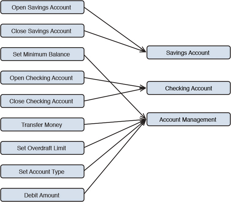
A friendly disclaimer: the technique I share here is by no means the only mechanism to identify interfaces and their operations. In fact, I’d submit that this is only one of the few techniques that I have used myself and found it to be successful more often than not. It is an effective one!
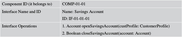
Capturing the outcomes in a way that fosters effective communication is paramount. The first part of the interface design is to document and model the interfaces and their operations with the proper signature and parameter list. Table 7.4 illustrates a format for capturing the information.
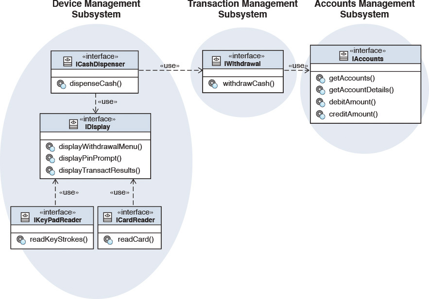
At this point, the interfaces are identified and their methods defined. Continuing with this work, the next task at hand is to identify how interfaces are dependent on other interfaces—interface dependency.
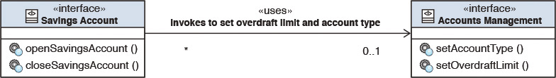
There are two types of interface dependency. The first type of dependency depicts how interfaces within a single subsystem are interrelated. The second type of dependency depicts how interfaces in one subsystem are related to or depend upon interfaces in other subsystems. This dependency is usually documented as a UML class diagram, wherein each class is stereotyped as an “interface” and association lines are used to depict the dependencies explicitly. A more complete definition takes this one step further to provide a complete textual description qualifying and elaborating on the exact nature of the dependency; for example, SavingsAccount::openAccount has a dependency on AccountsManagement::setAccountType, and so on. This is the recommended approach, but often the realities of time and cost constraints limit our freedom to exercise it.
Figure 7.5 shows a simple dependency of interfaces within a single subsystem, whereas Figure 7.6 shows an illustrative example of how interfaces may be dependent across different subsystems.
Identification and Association of Data Entries to Subsystems
The first two steps discussed so far focused primarily on component responsibilities. One of the fundamental aspects of component design is to identify the data entities that are owned by a subsystem and are used by the components to realize or implement its functionality.
The logical data model is used as an input to this task. The logical data model identifies the core business entities of the IT System to be built. A subsystem has a set of responsibilities to fulfill. These responsibilities, in turn, are implemented by the components that are encapsulated within the subsystem. The components expose the responsibilities through the interfaces and more specifically through the interface operations. Each of the interface operations requires data to be operated on to realize the functionality. The parameters on the interface operations are indicative of a logical grouping of data entities that are likely to be used and referenced together. Here is a simple set of rules to assist in identifying the data entities and associate them with subsystems:
1. Analyze, collect, and collate the parameter list on an interface.
2. Map the parameters to the closest business entities or data types in the logical data model.
3. Repeat steps 1 and 2 for each of the interfaces on a component.
4. Keep a running list of the data types that are identified.
5. Repeat steps 1 through 4 for each of the components within a subsystem.
6. Consolidate the list of data entities identified through steps 1 through 5.
7. Draw a boundary around the identified data entities from the logical data model and associate the data entities to the subsystem.
When you are following these steps, it is common to be faced with a situation in which you identify a few data entities belonging to more than one subsystem. For such entities, put on your architecture rationalization hat to analyze and assess which subsystem performs the primary operations on the data entity and determine the subsystem to be primarily responsible to own the data entity. An example of primary responsibility might be that a subsystem, say SUBSYS-01, may be responsible for the CRUD (Create, Read, Update, Delete) operations on a data entity, whereas another subsystem, say SUBSYS-04, may use the data entity to check the value of an attribute flag; for example, to check whether the customer is a premium or standard customer. In such a situation, your refactoring and rationalization thinking hat should influence you to associate the data entity to SUBSYS-01. Such a refactoring and rationalization activity is required for the data entities that are faced with this dilemma; some are intuitive, whereas some require you to exercise a little more gray matter!
Interface dependency should be captured, ideally using standard UML notations, explicitly identifying the dependencies of interfaces to the data entities. A picture is worth a thousand words, as the adage goes, and I recommend erring on the side of having more (rather than fewer) architecture and design diagrams while capturing the important architecture and design artifacts. You should typically develop UML model artifacts to depict the subsystem and component ownership of data entities. A good UML model, in this case, negates the necessity to provide textual descriptions for each of the data entities; you can refer to the logical data model to obtain such detailed descriptions for each of the data entities.
Component Interaction
During the logical-level design, we developed and captured a high-level component interaction diagram (see Figure 7.3). At the logical level, the components interacted; that is, they were invoked through pseudo operations only. From then until now, as a part of the detailed specifications, we have developed a significant amount of details in the form of an updated and elaborated component responsibility matrix, the interface’s specifications, and the identification and assignment of data entities to subsystems. At this stage, we have enough information on the components to update the component interaction diagrams: from pseudo invocations to real methods. The time is ripe and the information content rich enough to update the set of component interaction diagrams for the architecturally significant use cases with real method invocations. Figure 7.7 shows an example.
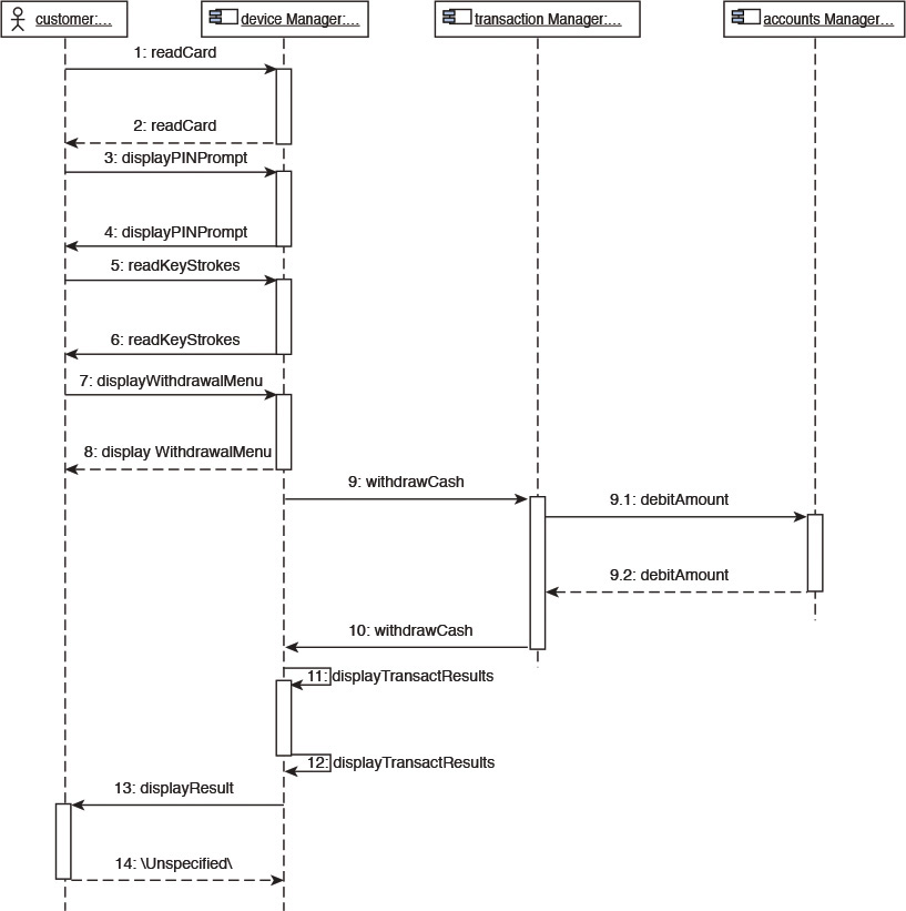
Figure 7.7 Component collaboration diagram (detailed) for Withdraw from ATM use case—an illustrative example.
Referring to Figure 7.7, although the details of all the components are not elaborated for the sake of brevity, you can see how the Accounts Manager component is invoked through the debitAccount method. When I analyze the artifacts in Figure 7.6 and try to relate them with the component interaction in Figure 7.7, I can see that the Accounts Management interface in Figure 7.6 has an exposed debitAccount method and can imagine how the Accounts Management interface is exposed by the Accounts Manager component in Figure 7.7. Now, if I can figure that one out, I am convinced beyond doubt that you had already figured it out!
For each UML sequence diagram, you ideally should capture a textual description of the step-by-step invocation of the operations on the components.
The level of specificity discussed here should be applied to all the architecturally significant use cases that were elaborated through component interactions during the logical-level design. In fact, as you drill down into more and more details and specificities, I advocate that you augment the list of use cases (that is, above and beyond only the architecturally significant ones). Doing so will not only provide additional overall coverage but also will exercise and validate most, if not all, of the operations on each of the interfaces. For each use case, UML sequence diagrams are used to draw the component interaction diagrams. Each component interaction diagram starts from an originating requestor (an actor), invokes specific operations on a series of components that collectively realize the use case, and typically returns the result to the originating requestor.
By this stage of the specification process, each subsystem is well flushed out with each of its components having a well-defined set of responsibilities that are, in turn, exposed through one or more interfaces; each interface is specified with a set of operations, with each operation being well defined through a list of input and output parameters, which, in turn, are mapped to one or more data entities that may or may not be owned by the subsystem. Sounds like a handful but actually it is quite trivial. Let me show you a little bit extra: even the overly loaded long preceding sentence can be pictorially represented through an object structure. The structure in Figure 7.8 depicts the relationship between subsystems, components, interfaces, and interface operations and is typically called the component meta-model.
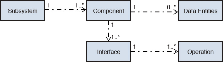
To summarize the component meta-model:
• A subsystem may encapsulate one or more components.
• A component may expose one or more interfaces.
• An interface may expose one or more operations.
• A component may assume primary responsibility of interacting with one or more data entities.
It is important to highlight that subsystems may also require refinement and refactoring after their initial identification. If a subsystem has grown to take up too much responsibility, it may be too complex to implement; if it looks to be less than optimal in features, it may need to be consolidated and merged with another related subsystem. Also, not all subsystems need to be custom built; some represent existing assets or products (for example, an HR module from an ERP package).
Component Assignment to Layers
Imagine that you were doing the design of a real-world IT System (for example, a banking application), and you identified and specified a list of system components (or a smaller set thereof), as shown in Table 7.5.
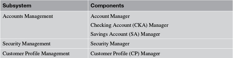
Above and beyond the components in Table 7.5, there would be a set of technical components that typically do not belong to any functional subsystem. An illustrative subset of technical components may be the following:
• DialogControl—Facilitates communication between the presentation components and the business logic components.
• Error Logger—Logs all application-specific errors and warnings into a file to facilitate subsequent diagnostics of application or system errors of failures.
• Relational DBMS—Stores the required data entities.
• ESB—Middleware component that serves as an information exchange layer facilitating mediation, routing, and transformation of data and protocols.
• Application Server—Middleware component in which the application will be deployed.
• Business Rules Engine (BRE)—Middleware component in which business rules are developed and hosted.
• Directory Server—Middleware component in which the user credentials and their access rights are modeled and stored.
Note the difference between functional components (that is, the ones in Table 7.5) and the technical components. The functional components encapsulate some specific business function or a subset thereof, whereas the technical components represent utility components such as DialogControl and ErrorLogger as well as technology tools and packaged applications such as RDBMS, ESB, BRE and Application Server, which are generally applicable to and leveraged by multiple functional components.
Recall from Chapter 5, “The Architecture Overview,” that one of the views of the architecture is the Layered view. Layering is a very important concept and technique in software architecture. Following are two value drivers of layering that I would like to reiterate:
• Enforces key characteristics for each layer that are influenced not only by the interlayer communication constraints and rules but also by the ever-so-important NFRs that are associated to and supported by the different layers
• Helps determine the placement of the components into the appropriate layers
Figure 7.9 depicts a representative allocation of the components, identified earlier, onto a layered view of the architecture.
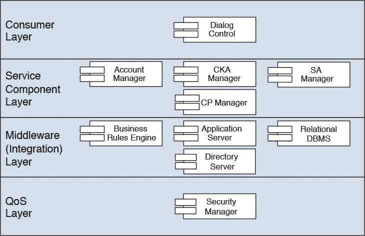
Obviously, this example does not show a complete layered view because it is missing quite a few layers from the layered architecture view in Chapter 5 and also a few components, for example, the ESB. Nonetheless, the idea here is to demonstrate the concept of component allocation to layers. (Notice, in Figure 7.9, that the QoS and Integration layers are depicted as horizontal layers, whereas in reality they are cross-cutting vertical layers. This depiction is done here for pictorial simplicity.)
The Layered view of the components and their placements on layers provides key data points on the physical-level design of the functional model—the topic of the next section.
Physical-Level Design
The physical-level design essentially revolves around two key elements:
• The choice of specific technology to implement the functional and technical components. For some technical components, the use of standard tools or products drives their implementation choice.
• The distribution of application components on a preliminary set of nodes so that they can be subsequently installed, configured, and hosted on physical hardware nodes, the latter representing the infrastructure topology of the system.
Hence, component design at the physical level focuses on the determination of the technology choice for implementation as well as the identification of the appropriate deployment components (nodes) on which the functional and technical components may be placed for runtime execution. Figure 7.10 shows a schematic of the nodal distribution of the components; that is, the placement of the components on infrastructure nodes.
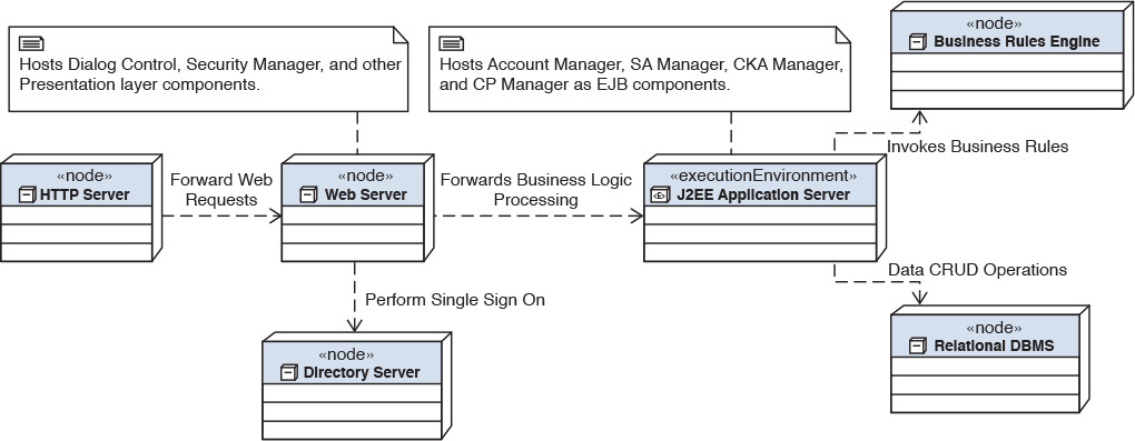
Notice in Figure 7.10 that the HTTP Server, Directory Server, Web Server, Relational DBMS, and Business Rules Engine are placed on dedicated physical machines while the J2EE Application Server is also placed on its own execution environment.
Many factors influence the decision of placing components onto deployment nodes. Specific NFRs and service-level agreements (SLAs) are core—availability, extensibility, latency, throughput, user response times, scalability, portability, and maintainability. The choice of technology is also critical; choosing between J2EE or .NET, choosing between leveraging a Commercial Off The Shelf (COTS) package software for business rules or custom developing them as a part of the embedded business logic, and choosing between a COTS portal technology for user experience or custom-developed user experience application front end, are some examples of decision points (specific to the illustrative banking example used here).
Now let’s peek at some of the rationale that may be used to arrive at the physical component design. Focusing on the 10 components in Figure 7.9, the decision (from a real-world implementation) to place the components on the physical infrastructure may be influenced by the following:
• HTTP Server on its own node—The application contains a good mix of both static as well as dynamic web content; the static content hosted on a dedicated HTTP server node that has built-in caching and other performance-optimizing techniques for better user experience. Further, based on the user traffic, this node can be mirrored and load-balanced to distribute the load from user requests.
• Web Server on its own node—The reasons for this are similar to the reasons for which the HTTP server is placed on a dedicated node. Additionally, horizontal scaling (more on horizontal scaling in Chapter 8, “The Operational Model”) of Presentation layer components, supporting peak loads and future projected workloads, is required to support the NFRs around user experience of the IT System. The node also hosts the DialogControl and the SecurityManager component.
• Directory Server on its own node—The COTS product that would implement the user repository typically mandates a dedicated environment.
• J2EE Application Server on its own execution environment—The technology chosen to implement the functional components—that is, Account Manager, SA Manager, CKA Manager, and CP Manager—is stateless session Enterprise JavaBeans (EJB) running on a J2EE platform. The NFRs around these functional components, especially the number of concurrent instances of each component that needs to be maintained, dictate a dedicated right-sized environment for execution.
• Business Rules Engine on its own node—The COTS product recommends a dedicated environment coupled with the fact that the transactional workload characteristics are different from other functional or technical components in the architecture.
• Relational DBMS on its own node—The NFRs around transactional workload metrics, along with concurrency requirements for simultaneous read and writes, mandate a dedicated compute node and environment.
Note that the reasons for your physical component design and placement decisions may be quite different from the ones presented here and would be dictated by the uniqueness of the NFRs, COTS products in the mix, and the choice of the implementation technology. You should use the example provided here as a guide to the thought process and decision-making criteria.
As you can see, physical-level component design provides a lot of information to influence the operational model of the system architecture—the topic of the next chapter.
Before closing out this chapter with the functional model for the Elixir case study, let me share some thoughts about functional modeling. Although the evolutionary steps of conceptual-, logical-, specified-, and physical-level design are apt and well thought out, time concerns often encroach upon projects, and frequently, architects must cut short their work activities. In such time-constrained situations, it is often beneficial to consider the specified-level design as the core first step in functional modeling; the artifacts that are typically identified in the conceptual and logical design phases can be built into the specified-level design artifacts. Thus, the practical architect is born!
Case Study: Functional Model for Elixir
Before returning to the case study, refer to the high-level components of Elixir that were identified in Table 5.1 in Chapter 5.
Here, I focus only on capturing the artifacts of the functional model and avoid illustrating the rationale behind each one of them. The technique followed is similar to what is described in the preceding sections on the general formulation of the functional model and its various artifacts.
Logical Level
This section illustrates the logical-level artifacts of the functional model of Elixir.
Subsystem Identification
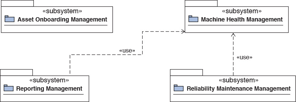
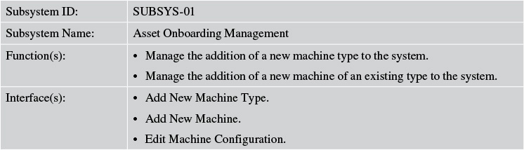
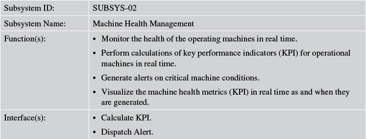
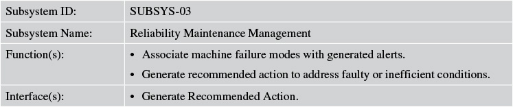
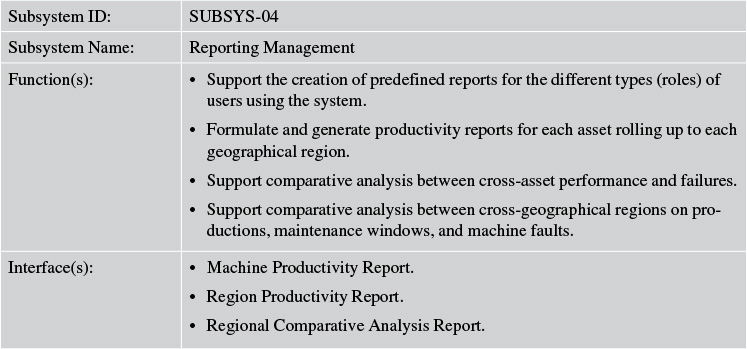
Four subsystems were identified for Elixir: Asset Onboarding Management, Machine Health Management, Reporting Management, and Reliability Maintenance Management. Figure 7.11 depicts the subsystems and their interrelationships.
Tables 7.6 through 7.9 expand on each of the subsystems and their functions.
Component Identification
Note that the components covered in this section are the functional components that are identified as a part of the subsystems. There is an additional set of components that are more technical in nature. The later section, on specified level design, has more details.
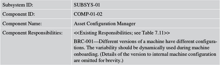
Tables 7.10 and 7.11 describe the components of the Asset Onboarding Management subsystem of Elixir.
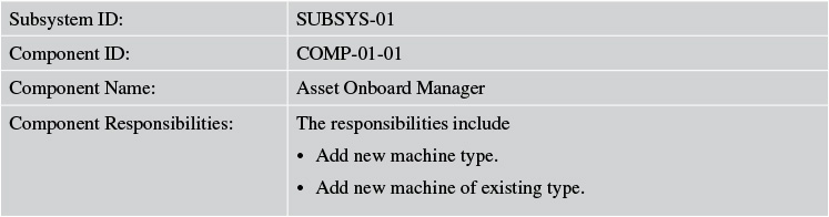
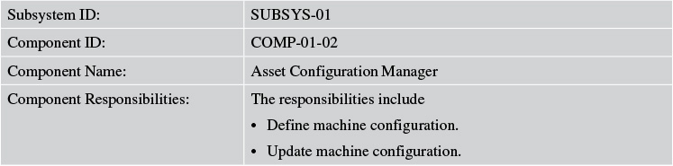
Because the preceding tables do not look too impressive or exciting, I have deferred the full details for each subsection of logical, specified, and physical design, wherever applicable, in Appendix B, “Elixir Functional Model (Continued).”
Component Collaboration
The logical level has three main architecturally significant use cases, namely:
• Machine Onboarding
• Generate Machine Alerts
• Recommend Work Orders
Figure 7.12 depicts the component collaboration for the Machine Onboarding use case.
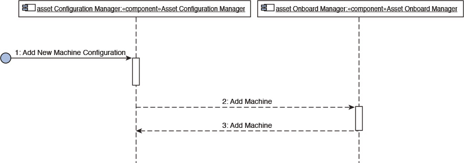
Refer to Appendix B for the other two component collaboration views.
Specified Level
This section illustrates the specified-level artifacts of the functional model of Elixir.
Component Responsibility Matrix
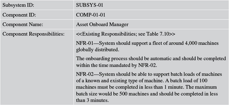
Tables 7.12 and 7.13 expand the component responsibilities of the first subsystem of Elixir, Asset Onboard Manager, to support the NFRs and business rules.
Interface Specification
Two interfaces are identified for the Asset Onboard Manager component of Elixir (see Tables 7.14 and 7.15).
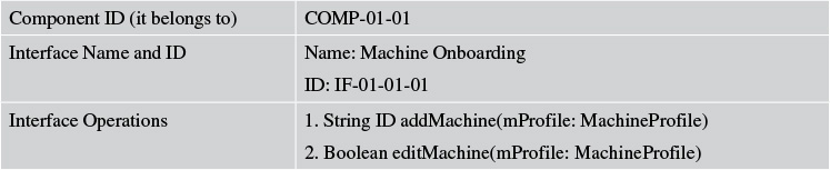
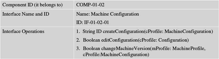
Refer to Appendix B for the component interface definitions for the rest of the components.
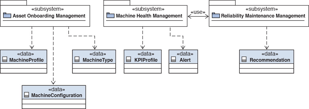
Associate Data Entities with Subsystems
Figure 7.13 depicts the most important data entities and their association to the subsystems of Elixir. Notice that the Reporting Management subsystem is not shown in the figure. The reason for its absence is that the Reporting Management subsystem uses most of the data entities to support the specific user reports; uses is the operative word here. As such, it does not own any specific data entities, only accessing them as appropriate.
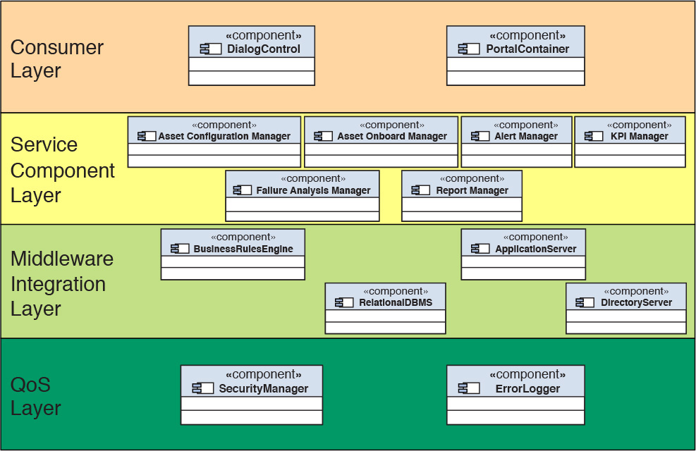
Component Assignment to Layers
Figure 7.14 depicts all the identified components (both functional and technical) of Elixir and their allocation to the different layers of a typical layered view of an architecture. Although one such component (that is, the ErrorLogger) is identified to be specific to Elixir, the components in the Consumer, Middleware, and QoS layers in Figure 7.14 are also part of the Elixir system. An additional component in the Consumer layer of Elixir—namely, the Portal Container component—is responsible for managing the interaction between the various user interface widgets and the user inputs.
Physical Level
The physical component design for Elixir is similar to the example used to illustrate the physical-level component design earlier in this chapter; Figure 7.10 and its associated narrative provide details on the techniques and criteria used to determine the physical-level design.
Figure 7.15 depicts the physical-level component design for Elixir. I explain only the additional (to Figure 7.10) nodes that appear in this diagram.
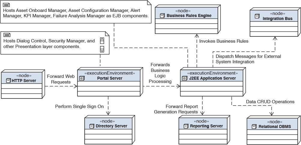
Portal Server on its own node—The user requests are forwarded to the portal server node, which is the gatekeeper for application-level security and access control. It leverages the Directory Server component to implement the security and access control. The portal server maintains the user interface of Elixir and forwards the business logic processing to the J2EE Application Server component. The Presentation layer NFRs dictate that it be placed on its own node.
Reporting Server on its own node—This node hosts the COTS package that will be used as the reporting engine for Elixir. Support for ad hoc and preconfigured reports on machine health and production metrics are among the core features of Elixir. The number of concurrent users requesting reports and the sheer number of reports necessitate the reporting server be hosted on a dedicated node.
Integration Bus—This is a separate dedicated node for the ESB technical component. The middleware COTS package currently owned by the client is already hosted on its own dedicated infrastructure (a.k.a. node) and hence the choice was simple.
Note: Keep in mind that a lot of software engineering best practices and techniques are employed to determine the rationale for component placement on physical nodes. A detailed study of these practices and techniques is beyond the scope of the current discussion.
Summary
The functional model is one of the most important domains of software architecture. A well-designed functional model is the key to building a robust and functional system architecture. The functional model not only addresses the architectural techniques used to deconstruct the problem domain into a set of architecture artifacts but also illustrates how to progressively build upon them by incrementally moving from the abstract to more detailed architectural constructs. The functional model is iteratively built through the four major phases of conceptual-, logical-, specified-, and physical-level design—a methodical approach that reaps maximum value.
Due to the time-critical nature of almost all IT projects, a four-step rigor may not be a natural fit. As such, it is acceptable to initiate the focus on the logical-level design and then progressively build the detailed functional model. In more time-critical situations, it is okay to take a calculated risk of initiating with the specified-level design. However, compromising on apportioning commensurate time and focus on the specified-level design will certainly defeat the purpose of this architecture and design work effort.
The main focus of this chapter was to provide a bit of a prescriptive guidance on how to go about iteratively and incrementally developing the functional model, focusing on the essential artifacts to capture and the techniques that may be used to rationalize the decision-making process. While the discourse may be quite detailed, the framework is not too hard to grasp:
• Identify the subsystems that could form a natural grouping of capabilities.
• Identify components, for each subsystem, that would work together internally (to the subsystem) to support the subsystem capabilities.
• Identify the subsystems that will hold primary ownership of the core data entities of the system.
• Identify the interfaces, on each of the components, that will collectively expose and implement the component functions.
• Determine the placement of the components onto a layered view of the system architecture and subsequently onto a set of logical infrastructure components.
And that’s all there is to it!
The Elixir case study now has a functional model. So as not to extend this chapter beyond what is necessary, the complete details of the functional model artifacts of Elixir are available in Appendix B.
Take a moment now to give yourself a well-deserved pat on the back if you have come this far in the book. I have seen many software architects who only dwell in what has been covered so far in this book, and they still make quite a good name and fan following for themselves!
The physical-level functional component design is a very good segue into the operational model—the topic of the next chapter!
References
Gamma, E., Helm, R., Johnson, R., & Vlissides, J. (1994). Design patterns: Elements of reusable object-oriented software. New York: Addison-Wesley Professional.
IBM. (2005). Component business models: Making specialization real. Retrieved from https://www-935.ibm.com/services/us/imc/pdf/g510-6163-component-business-models.pdf.
Jacobson, I, Booch, G., Rambaugh J. (1999). The unified software development process. New York: Addison-Wesley Professional.
Object Management Group (OMG) (2011). Documents associated with Unified Modeling Language (UML), v2.4.1. Retrieved from http://www.omg.org/spec/UML/2.4.1/.