
Chapter 9. Integration: Approaches and Patterns
Come together, my building blocks—lego my creation!
Gone are the days when an IT System with only a web front end and a back-end database was good enough for an enterprise to drive competitive advantage through IT automation. Current IT ecosystems are expected to support systems of systems: systems require complex interconnects; data (of wide variety, generated in varied volumes and velocities) needs to be converted into information, information into knowledge, and knowledge into insights. The need for systems integration has never be more demanding than it is now.
This chapter explores some of the essential techniques around systems integration. The focus is on understanding the various patterns of integration and identifying illustrative scenarios in which the patterns may be applicable. The patterns essentially revolve around codifying repeatable techniques to enable the linkage between customer-facing solutions, back-end systems, databases, and external systems. While patterns (in the context of IT Systems) are awesome, their real value is harnessed when one or more such patterns can be instantiated in real-world scenarios to solve architectural problems. This chapter demonstrates how some of the integration patterns, which I present, may also be used in the Elixir system.
And for you, the architect, a strong knowledge of some of the key integration techniques and patterns is destined to be a killer arrow in your architecture quiver!
Why We Need It
Many, if not most, organizations have made huge investments in their IT and legacy systems that, more often than not, they plan to leverage. Treating systems as corporate assets necessitates a conscious and coordinated effort to maximize their shelf life and life span. Increasing customer demands for timely and actionable insights warrants an integration pipeline that generates information from data, knowledge from information, insights from knowledge, and prescriptive actions from insights.
Appropriately integrated systems provide the ability to support business agility—adaptation to rapidly changing business needs and IT’s ability to react to such changes. Horses for courses—different integration techniques for different scenarios—are required; some focusing on efficient routing of data, some on adapters to different technologies, some on asynchronous low volume data exchange, and some others on mediation between different systems, among others. A catalog of such integration patterns along with prescriptive guidance on their usage ensures consistency in the ways they are leveraged to address some foundational architectural problems.
Approaches to Integration
As an architect, a practical one at that, you may be frequently confronted with nagging questions regarding how the capabilities of two or more systems can be harnessed in an effective and flexible manner. You may be faced with problem statements like these:
• I have system X and system Y, which have traditionally not talked to each other. How would you go about integrating them?
• What is the best way to interconnect system A with system B and system C such that it does not affect the transactional throughput of system A?
Sound familiar? I bet they do!
There are several approaches to integration. The ones that you may tend to leverage the most to address a majority of your practical integration challenges might be categorized as follows:
• Integration at the glass, a.k.a. user interface (UI)–level integration
• Data-level integration
• Message-oriented integration
• Application programming interface (API)–based integration
• Service-based integration
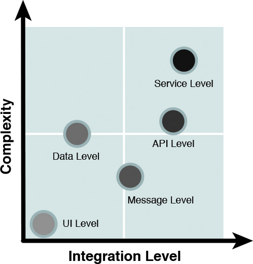
The integration approaches vary in two respects (see Figure 9.1):
• The level of integration—The layer, in the architecture stack, at which the integration takes place. As an example, you can integrate two systems through the services they expose in the services layer, or you can just mash up the components at the consumers (that is, Presentation) layer. (Refer to Chapter 5, “The Architecture Overview,” for a recap on the Layered view of the architecture.)
• The complexity of integration—The technology challenges and the level of effort involved in implementing the integration. As an example, data-level or API-based integration may be more involved (functionally and also to support the nonfunctional requirements, or NFRs) than integrating presentation logic.
The following sections elaborate on each of the integration approaches.
User Interface Integration
Integration of systems at the Presentation layer (a.k.a. user interface integration) is often used when the systems that are front ended with the presentation layer are too archaic to be integrated at the systems layer. The main reasons for the lack of systems integration are typically attributed to lack of technology skills in legacy back-end systems and hard-to-use exposed APIs. However, often, such legacy back-end systems may require a face lift; that is, a better and more modern user interface, to modernize the look and feel while preserving the rock-solid back-end legacy systems.
Some of the techniques employed in implementing this approach are the following:
• Develop a modern front end for existing legacy systems. Green screens are typical examples of user interfaces (for mainframes and legacy systems) that may require a modern way of user interaction.
• Develop or leverage an intermediary program that can convert the user interactions on the modern front end to a data format and transfer protocol that is used to communicate with the legacy system.
User interface integration has its own benefits and perils. On the upside, the implementation is relatively easier than integrating at one of the systems layers (that is, data, API, or services), requiring no change to the back-end systems and with the potential of reusing the security of the host system. On the flip side, though, the screen limitations (scrolling, absolute screen positions for fields, and so on), along with the lack of skills in legacy technologies, often become problems that are hard to address. The fact that such integrations can extend the lifetime of an otherwise ready-to-be-retired system can be either a blessing or a curse—your pick!
Note that, although this is often understood as the simplest integration approach, the archaic nature of legacy systems and the specific user interface technologies that may be used often make such an integration quite a nightmare. So do not be fooled into submission that you adopted the easiest approach!
Data-Level Integration
Data-level integration is often the most commonly used technique to integrate multiple systems. In this approach, two or more data systems are integrated by implementing a set of replication and synchronization processes that link the underlying data models of multiple potentially disparate systems. This technique is commonly implemented when building new systems that need to access data from multiple and disparate existing systems. Rather than re-create the data from scratch, the objective is to reuse the existing data after giving it a shape and form that is more commensurate with the needs of the system to be built.
Data integration techniques can be put into two broad categories: namely, federation and replication. Let’s take a closer look at the two categories.
In the federated integration technique, the source data is kept in place. The data needs of the system being built are carefully analyzed, and a semantic data model (see the “Semantic Model” sidebar) is developed. The model provides the level of abstraction that decouples the model user from the underlying physical data sources or systems. The federated integration technique provides a data interface to the consumers of the data while implementing the interface by retrieving the data from one or more source systems, or systems of record (SOR). In this technique, there is no need to physically replicate the relevant data from multiple source systems into a single repository. Keep the data where it is, and provide a data interface that supports the way you need to use it. Figure 9.2 depicts this implementation schematic.
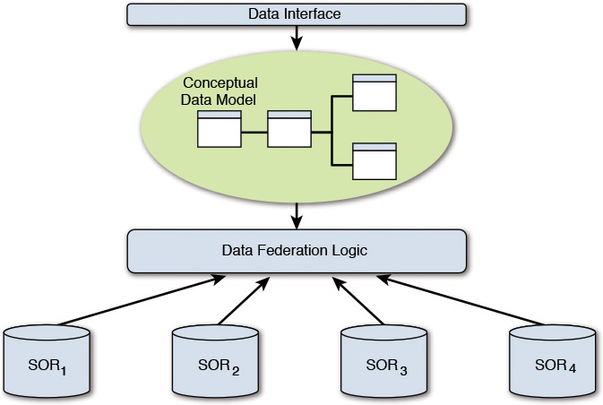
The advantage of this technique is that the source data need not be moved and duplicated. The obvious disadvantage is that the data federation logic is coupled to any change in the underlying systems of records. There are other pros and cons; however, these two primary ones should suffice to give you some guidance on evaluating its adoption.
In the replication technique, data from multiple, possibly disparate, source systems is first copied over, or replicated into, a single data repository. The conceptual data model would thus have a single physical instantiation in the replicated data repository. Figure 9.3 depicts how the technique is implemented.

Message-Level Integration
Message-level integration is a technique that facilitates integration with back-end systems and databases based on asynchronous or pseudo synchronous communication. This integration technique is an example of loose coupling between one or more source systems (which are considered to be producers of data) and one or more destination systems (which are considered to be consumers of data).
The unit of communication is a message, which is a textual (most commonly) representation of data exchange between two or more systems. The capabilities are provided by a software system called the message-oriented middleware (MOM). The MOM is configured such that paths of communications, called channels, may be established to link the message producers with the message consumers.
In the true asynchronous communication mode, the message producer publishes a message on a message queue. One or more consuming applications can subscribe to the particular message of interest. Each consuming application may have its custom integration methods of consuming the message. In the pseudo synchronous mode, the messaging middleware periodically polls the source system for new data. Once it retrieves the new data, it makes the data available on a message queue. The consumption techniques, for the systems that are message consumers, remain the same. (See the “Message Queue and Topics” sidebar.)
It is important to note that a data producer can also become a data consumer and vice versa. The ability to publish data onto the messaging middleware makes the publishing system a message producer; the ability to consume predefined messages from the messaging middleware makes the consuming system a message consumer; popularly known as the publisher-subscriber (pub-sub) technique of data exchange. In pub-sub, the form of data exchange not only allows multiple consuming applications to subscribe to a single message of interest but also allows the message producer to be a message consumer and vice versa. Figure 9.4 depicts the high-level components for this type of integration.
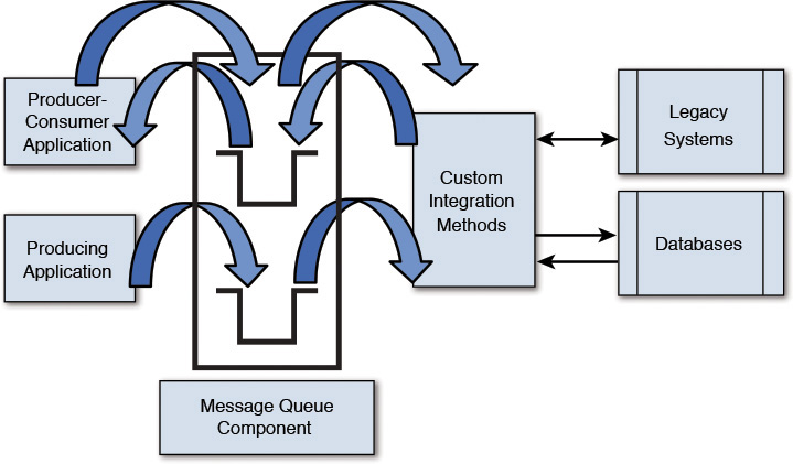
Coming back to the concept of loose coupling, the messaging middleware is the trick to decoupling the message producers from the message consumers. Referring to Figure 9.4, the Custom Integration Methods are implemented as adapters. An adapter is a piece of code that provides a technology-specific implementation to interface with specific technology systems. An adapter masks the details of technologies (for example, exchange protocols and data formats) and provides an interface through which data is being translated and transferred to and from an underlying system. You may have come across the terms JDBC adapter (implementing the Java for DataBase Connectivity protocol for data communication), legacy adapters (implementing the legacy APIs and data formats for data exchange), and so on. The adapters, which are essential to message-level integration between disparate and heterogeneous systems, enable the underlying back-end systems to change independent of the invoking clients and also ensure that the invoking clients may not need to have any knowledge of the underlying data model of the back-end systems.
Message-level integration supports many processing models, of which send and forget and store and forward are very common. In the send and forget technique, the sending application sends the message to the message channel of the MOM, after which the sender can safely forget everything about its message-sending responsibility. The MOM takes care of actually transferring the message in the background to the receiving application. The store and forward technique is based on the principle of guaranteed delivery of messages. It is used in scenarios in which the message consumer may be intermittently available. In this technique, the messaging middleware stores the message on the physical server of the sending application, forwards the message to the receiving application, and stores it again in the physical server of the receiving application. Once the receiving application acknowledges the receipt of the message, the stored copy is purged.
This technique, along with its variations, remains one of the most commonly used patterns for loosely coupled integration between systems.
API-Level Integration
Application programming interface (API)–level integration is a technique in which multiple systems are integrated together through a set of invokable functions that are exposed for consumption by the individual systems. Systems—custom applications (for example, developed in J2EE or .NET), packaged applications (for example, SAP, JDEdwards), and legacy applications (for example, IBM mainframe 3270 application)—encapsulate their application-specific functions and expose interfaces through which such functions are made available. The APIs provide a tight integration with the underlying systems. The APIs are primarily synchronous in nature.
API-level integration has been in practice for many decades and has a fairly mature market with system vendors continuously expanding on their offerings. It is quite common to use API-level integration to build higher-end applications as composite business services. A composite business service can be built in a couple of different ways:
• Same function, multiple implementation—In such a scenario, a common application function (that is, a function that provides the same business functionality; for example, pay by credit card) is exposed by more than one application or system. A standard API is built with a consistent interface (for example, makePayment) and exposed for consumption. The same interface is implemented by more than one system. The routing of the interface implementation to one of the multiple systems (that support it) is typically done during the runtime, or invocation, of the interface. The runtime routing is typically controlled by a set of policies based on which a specific API provider, or system, is invoked. An example could be a credit card gateway system that takes MasterCard, Visa, and American Express. While the payment function is the same, the application of transaction fees varies between the card types. The application of the transaction fees is driven by policy and rules that are applied only during runtime; that is, at the time of invocation.
• Multiple functions combined into a business process—In such a scenario, an end-to-end business process is implemented by orchestrating functionality that is exposed by different application functions. A business process management (BPM) engine provides the glue to integrate the invocations of multiple APIs, from multiple systems, to realize an end-to-end business process. The BPM engine wires the participating system APIs, maintains the sequence of API invocation, manages the processes’ state between subsequent interactions, and also provides transactional integrity for the end-to-end process. Consider an example of an e-commerce application: browseItems could be exposed by a legacy mainframe inventory system, createOrder exposed by a .NET application, and makePayment by a third-party credit card gateway application. Since each of the participating systems is implemented using different technologies, corresponding technology adapters may be used to invoke the exposed APIs.
The main advantage of API-level integration is that the calling programs need not know the underlying data model or application logic of systems that expose the APIs; the underlying business logic and data model can be changed with minimal effect on the integrated application. The challenge lies in the choice of the functionality to be exposed. APIs often may be costly to implement (for example, some technology may be legacy, and skilled resources may be difficult to find). Also, not only does the proper functioning of the API depend on the availability of the back-end system, but also the implementation of an API to work in a distributed environment (for example, CORBA, DCOM) may be expensive. (Refer to the Object Management Group and Microsoft Technet articles in the “References” section.)
Note: The term API and its use have evolved to also include Web APIs. Web APIs are the defined interfaces through which interactions happen between an enterprise and applications that use its assets, often including mobile applications. Web APIs are what more and more people tend to imply when they are discussing APIs. However, the traditional definition of API, as this section illustrates, still holds true.
Service-Level Integration
Service-level integration is often considered the holy grail of systems integration. One of my colleagues in IBM stated this integration type in a very simple and succinct manner; according to Dr. Ali Arsanjani (2004):
Service-oriented integration is an evolution of Enterprise Application Integration (EAI) in which proprietary connections are replaced with standards-based connections over an ESB notion that is location transparent and provides a flexible set of routing, mediation, and transformation capabilities.
As stated here, the essential difference between API-level integration and service-level integration is the standardization of a single technology framework to implement, expose, and invoke a piece of business function. Service-level integration, specifically the use of Web Services, its most prevalent implementation technology, is ideal for situations in which out-of-process and distributed (that is, across multiple different physical machines and networks) functions, from different application domains, are required to support the orchestration of a business process.
While this chapter does not go into the details of Web Services, it touches on some of its most commonly used solution topologies:
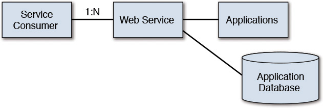
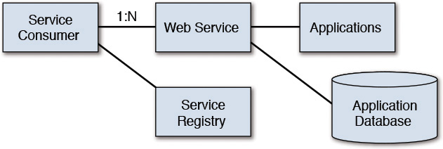
• Direct Connection—In this topology, an application provides either a simple service to access its business data and business functions or a direct access to its underlying database. In such a simple setup, multiple service consumers can invoke the Web Service (which is the technology used to expose the service). The service consumers are expected to have prior knowledge of where the service is located (that is, its endpoint URL) such that it can initiate an early binding to the service interface. See Figure 9.5.
• Dynamic Binding—In this topology, the service consumer has prior knowledge only of a service registry (Abeysinghe 2014). The consumer locates the actual service from the service registry during runtime, binds to the service endpoint URL dynamically, and then invokes the service. See Figure 9.6.
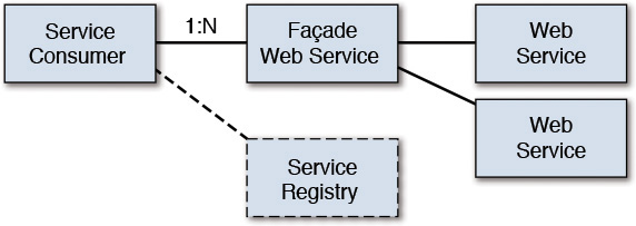
• Composition Service—In this topology, the service consumer locates the service in the same mechanism as in dynamic binding. However, the located service is a facade over multiple back-end Web Services; the facade Web Service invokes and composes multiple Web Services to deliver the end functionality. See Figure 9.7.
This discussion completes our brief illustration of the most commonly employed techniques for integration.
Integration Patterns
The various approaches to integration are now in your repertoire. If only you could formulate a set of repeatable and reusable solutions that supplement the various integration approaches. Enter the integration patterns!
A detailed discussion of the numerous integration patterns would require a book unto itself; however, it is necessary to highlight some of the key integration patterns that may be employed to solve a significant chunk of the problem space. In the spirit of this book, I rely on the 80–20 rule: be aware of the most common patterns and then research and learn additional ones that may be required when faced with some unique problems. Or better still: develop a new integration pattern yourself!
The following sections help raise your awareness of the ones that you will practically use more often than not. Fasten your seatbelts for a rapid-fire round of pattern introductions.
Further information can be found in Gregor and Woolf (2003), an entire book dedicated to integration patterns.
Synchronous Request-Response
Problem Statement
How can we send messages from the source to the target and expect an immediate response?
Solution
Establish connectivity between the sender and receiver applications, and use an interface to send the message from the sender to the receiver.
Assumptions
• The source and target applications are simultaneously available, and the message request is processed in real time with the requester application waiting for the response in a synchronous manner.
• Typically, only one message is processed at a time between a request and response turnaround.
Batch
Problem Statement
How can we send messages from the source to the target application in the scenario that the source and target may not be simultaneously available?
Solution
Send data from the source to the target application in periodic intervals.
Assumptions
• No real-time processing is expected.
• The focus is not on real-time processing, and hence, larger (than supported by any optimal request-response) volumes of data may be processed.
• Optionally, a single response may be sent back to the source application upon completion of the processing of the group of messages.
Synchronous Batch Request-Response
Problem Statement
How can we send more than one message and expect them to be processed together?
Solution
Send a group of messages from the sender to the receiver application at the same time and have the receiver application send an acknowledgment back to the sender application on receipt of the message. The results can be made available at a later point in time.
Assumptions
• More than one message typically constitutes the input request.
• The group of messages is expected to be processed together.
Asynchronous Batch Request-Response
Problem Statement
How can we send a large volume of messages and expect them to be processed together?
Solution
Send the large volume of messages in a batch mode; that is, non real time. Expect neither an acknowledgment (of message receipt) nor the results immediately.
Assumptions
• More than one message typically may constitute the input request.
• Large message volumes are expected.
Store and Forward
Problem Statement
How can the sender be assured that the message is delivered to the receiver even under the circumstances of a failure of the messaging system; that is, the MOM?
Solution
The message is persisted to a local persistent store at every point in the message’s journey through the MOM. The sender stores a copy of the message in a local persistence store before sending the message to the next recipient in the chain. Only after an acknowledgment is received from the receiver does the send operation actually complete, and the message copy is removed from the local store. This action of locally storing the message before acknowledgment receipt from the next receiver daisy-chains until the message is received at the final destination.
Assumptions
• The MOM technology supports message persistence.
Publish-Subscribe
Problem Statement
How do we send messages simultaneously to multiple recipients?
Solution
Leverage the MOM feature of a message topic that allows recipient applications to subscribe to the message topic. The message, once published in the message topic, is available for all subscribed recipients to consume the message.
Assumptions
• The recipient applications are not known by the source (that is, the sender) application.
• The source application generally does not expect to receive a response.
• Transactional integrity may not be implemented across all the target applications.
Aggregation
Problem Statement
A request from a source application requires functions from multiple target applications to fulfill the request.
Solution
The incoming request from the source application is used to create requests that are specific to the target applications. The target application-specific requests are executed in parallel. The results from all the target applications are collected and grouped (hence, the name Aggregation) together. The response is sent back to the source application.
Assumption
• Intermediate message mediation and routing logic are required to create target application-specific requests and route the requests to the target applications and also to aggregate the responses.
Pipes and Filters
Problem Statement
How can we deconstruct and simplify the processing of complex messages and localize the processing into reusable building blocks?
Solution
Deconstruct the problem into reusable functions and then chain the reusable functions in sequence to obtain the expected outcome. The reusable functions are called filters, and the components that connect the output of one filter with the input of the next one are called pipes. Each filter has one input and output port, respectively, which the pipes use to establish connectivity between two adjacent filters in the workflow.
Assumption
• The incoming message is complex and requires multiple types of processing in sequence to get to the expected action or result.
Message Router
Problem Statement
How can a message be successfully routed to the receiver if the sender is unaware of the message’s final destination?
Solution
Introduce a special type of filter called a router. The router will send the message either to a different output channel or to the next filter in the workflow. The routing logic is based on business rules applied on the message content itself. The content and the rules will direct the message to its final destination.
A variation of this scenario is one in which multiple output destinations (or message channels) can announce their ability to handle a message, based on some conditions and rules. The router evaluates the various conditions (published by different destination channels) upon the arrival of a message and dynamically chooses the destination where the message is sent.
Assumptions
• Business rules, which determine the routing logic, are configured into the MOM and available at system startup.
Message Transformer
Problem Statement
How can the sender and receiver applications communicate if they do not agree on the message format?
Solution
Convert or translate the original request message into a message format (that is understood by the receiver application) before sending the message to the receiver application. The translation is typically done by an intermediate messaging component that is a part of the MOM.
Assumptions
• Sender and receiver applications are heterogeneous and use different technology.
To summarize this section, I elaborated on 10 commonly used integration patterns. There are many variations, some of which can be termed patterns in their own rights. It is not uncommon to combine multiple patterns to solve a specific integration challenge.
Keep in mind that this list of integration patterns is not exhaustive; they are intended to give you enough practical knowledge of leveraging integration techniques and patterns for your solution architecture.
Case Study: Integration View of Elixir
The architecture of the Elixir system uses two levels of integration: namely, data-level integration and message-level integration. It also employs two of the integration patterns: the Asynchronous Batch Request-Response and the Message Router patterns.
Let’s review the architecture components of Elixir, which were illustrated in Chapter 5. Referring to the components in the Data & Information layer and the Technology Enablers layer, I picked the set of components that are the primary participants of an integration view of Elixir (see Table 9.1). Because I use their abbreviated names, yes, you may have to go back to Chapter 5 and refresh your memory!
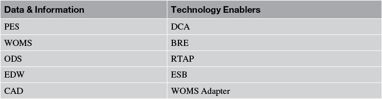
Figure 9.8 depicts a subset of the system’s data flow, which takes advantage of either an integration approach or an integration pattern or both.
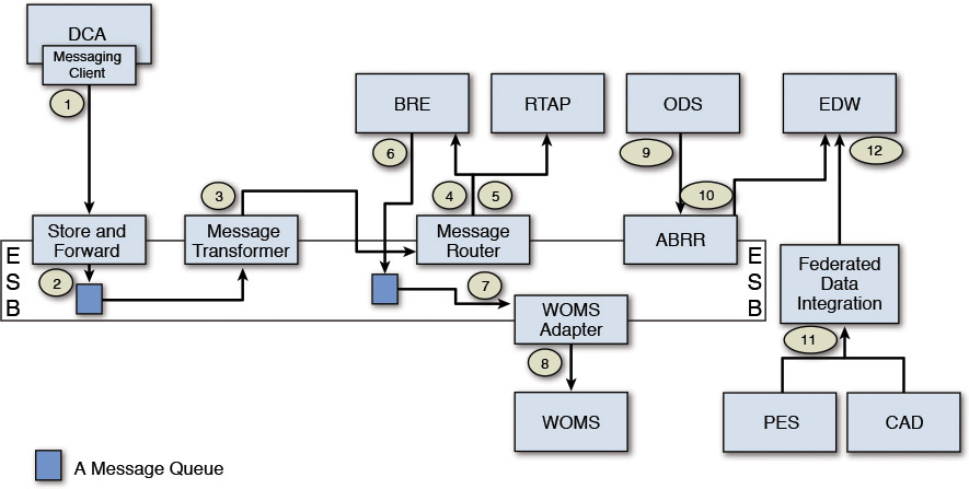
The following sections walk through the four data flows, highlighting the integration patterns along the way. The walkthrough is broken down into four groups: labels 1 through 5, labels 6 through 8, labels 9 and 10, and labels 11 and 12. The rest of the section illustrates the data flow for each of the four groups.
Following Flow Labels 1 Through 5
The DCA uses a messaging client to connect to the ESB and dispatch the machine data (that is, the messages) to a predefined queue (or set of queues). It uses the Store and Forward pattern to ensure guaranteed delivery of messages. An ESB component, which implements the Message Transformer pattern, picks up the messages and transforms the message format from its native incoming form to a predefined, agreed-upon data format (for example, from sensor time series data format to JSON format). The transformed message is sent to an input node of a Message Router. The router dispatches the messages to two systems: the BRE and RTAP.
Note: I purposefully omitted additional details here for the sake of brevity. As an example, the Message Router executes business rules to determine, in this case, that both BRE and RTAP are eligible recipients, each receiving different subsets of the incoming message. The Message Router component puts the different messages in different queues to which the BRE and RTAP, respectively, listen and subsequently pick up the relevant messages.
Following Flow Labels 6 Through 8
The output of the BRE is a set of recommendations generated by Elixir. These recommendations are asynchronously generated and dropped into a message queue. The WOMS adapter is configured to listen for incoming messages on the queue. Upon arrival of a new message, the WOMS adapter picks up the message, transforms it into a message packet that is understood by the WOMS system, and invokes a WOMS API to transmit the information.
Note: WOMS, in this case, creates a new work order.
Following Flow Labels 9 and 10
Before starting, I must admit I used an abbreviated name in Figure 9.8 that I have not defined before: ABRR stands for Asynchronous Batch Request-Response.
The data in the ODS needs to be moved to the EDW in periodic intervals; the amount of data moved in each invocation is very high in volume. The Asynchronous Batch Request-Response message pattern is used to trigger the asynchronous, periodic, bulk movement of data.
Note: The data in the EDW is used for business reporting and analysis.
Following Flow Labels 11 and 12
The EDW aggregates data from more than one system of record. Elixir uses one of the data-level integration patterns called the Federated Data Integration pattern (see Figure 9.2) to consolidate data from the CAD and PES systems and move a replicated copy of the necessary data (from each of the two source systems) into EDW.
Note: Mapping this flow from Figure 9.8 to the elements in Figure 9.2, the CAD and the PES are the two SORs, the federated data integration is the data replication, and the EDW is the single repository. Note also that the CAD system is out of scope of the initial release. However, the integration pattern used would be very similar to the one used to integrate with the PES system. Hence, the CAD system is depicted in the flow. In the first release, the CAD integration will not be implemented.
And now, the Elixir system architecture has leveraged a set of integration patterns!
Summary
This chapter focused on two main areas: integration approaches and a set of integration patterns. It discussed five major approaches to integration—UI level, message level, data level, API level, and service level—and also ranked them in their varying order of complexities (from an implementation standpoint), discussing the pros and cons of each of them along the way. While all the approaches are in use, the message-level integration approach is the most pervasive, has been tested the most over the years, and has the most number of variants. The UI-level integration approach finds a very niche usage when trying to modernize legacy systems by giving them a facelift. The data-level integration is also quite commonly used and has also been around for many years, tried and tested. The API-level integration sprung into existence when vendors tried to expose their software capabilities through a set of interfaces in an effort to participate in larger systems integration efforts. The service-level integration took the API-level integration approach up a few notches and standardized the ways in which distributed systems could interact and participate to foster an ecosystem of capabilities that could be choreographed and orchestrated to build complex systems.
This chapter also described 10 fundamental integration patterns that not only are used in their own rights but also are capable of being coupled together to solve specific integration problems. Although the 10 integration patterns discussed in this chapter can provide a very solid foundation, they are not exhaustive by any means. If these patterns, or their combinations, fall short of solving an integration problem, you should research other patterns. That said, this list should give you a firm base from which there is only one way to go—higher!
The solution architecture of Elixir now has an integration view that can be further elaborated and refined. A data flow view of the system was chosen to depict how the various integration approaches and patterns can be bundled together to realize a subset of the solution—the integration aspects of the solution, that is.
Integration approaches and patterns—the techniques and know-how to leverage them in the architecture and design of enterprise solutions—are among the fundamental abilities that any established solution architect must possess. In fact, one of my key criteria to verify the credentials of a solution architect is the viability of her capabilities in the integration space; if she does not have knowledge of too many software products and technologies, that is still okay, as she can pick them up. However, lacking integration skills does not serve a solution architect too well, at least when looking at her through my eyes in search of any suitable solution architect.
If you have successfully come this far in the book, you are fast gaining a distinct advantage over your budding solution architect peers who are not following this script the way you are; the distinctness of the advantage is much more palpable against those who have not picked up this book yet!
Where next from here?
References
Abeysinghe, A. (2014, July 24). API registry and service registry. Solution Architecture Blog. Retrieved from http://wso2.com/blogs/architecture/2014/07/api-registry-and-service-registry/
Arsanjani, A. (2004, November 9). Service-oriented modeling and architecture: How to identify, specify, and realize services for your SOA. IBM developerWorks. Retrieved from http://www.ibm.com/developerworks/library/ws-soa-design1.
Gregor, H., & Woolf, B. (2003). Enterprise integration patterns: Designing, building, and deploying messaging solutions. New York: Addison-Wesley Professional.
Microsoft Technet. (n.d.). Distributed component object model. Retrieved from https://technet.microsoft.com/en-us/library/cc958799.aspx
Object Management Group (OMG). (n.d.). The CORBA specification. Retrieved from http://www.omg.org/spec/CORBA/