
Lesson 5. Working with Table Relationships
After you add the tables to your database, you next establish relationships between them. This helps to ensure the integrity of the data that users enter into the system. In this lesson, you learn:
![]() What relationships are and why you would want to use them
What relationships are and why you would want to use them
![]() How to work with database diagrams
How to work with database diagrams
![]() How to work with table relationships
How to work with table relationships
![]() How to designate table and column specifications
How to designate table and column specifications
![]() How to add a relationship name and description
How to add a relationship name and description
![]() How to determine when foreign key relationships constrain the data entered in a column
How to determine when foreign key relationships constrain the data entered in a column
![]() How to designate
How to designate INSERT and UPDATE specifications
An Introduction to Relationships
Three types of relationships can exist between tables in a database: one-to-many, one-to-one, and many-to-many. Setting up the proper type of relationship between two tables in your database is imperative. The right type of relationship between two tables ensures:
![]() Data integrity
Data integrity
![]() Optimal performance
Optimal performance
![]() Ease of use in designing system objects
Ease of use in designing system objects
This lesson discusses many reasons for these benefits. Before you can understand the benefits of relationships, though, you must understand the types of relationships available.
One-to-Many
A one-to-many relationship is by far the most common type of relationship. In a one-to-many relationship, a record in one table can have many related records in another table. A common example is a relationship set up between a Customers table and an Orders table. For each customer in the Customers table, you want to have more than one order in the Orders table. On the other hand, each order in the Orders table can belong to only one customer. The Customers table is on the one side of the relationship, and the Orders table is on the many side. For this relationship to be implemented, the field joining the two tables on the one side of the relationship must be unique.
In the Customers and Orders tables example, the CustomerID field that joins the two tables must be unique within the Customers table. If more than one customer in the Customers table has the same customer ID, it is not clear which customer belongs to an order in the Orders table. For this reason, the field that joins the two tables on the one side of the one-to-many relationship must be a primary key or must have a unique index. In almost all cases, the field relating the two tables is the primary key of the table on the one side of the relationship. The field relating the two tables on the many side of the relationship is called a foreign key.
One-to-One
In a one-to-one relationship, each record in the table on the one side of the relationship can have only one matching record in the table on the other side of the relationship. This relationship is not common and is used only in special circumstances. Usually, if you have set up a one-to-one relationship, you should have combined the fields from both tables into one table. The following are the most common reasons why you should create a one-to-one relationship:
![]() The number of fields required for a table exceeds the number of fields allowed in a SQL Server table.
The number of fields required for a table exceeds the number of fields allowed in a SQL Server table.
![]() Certain fields that are included in a table need to be much more secure than other fields included in the same table.
Certain fields that are included in a table need to be much more secure than other fields included in the same table.
![]() Several fields in a table are required for only a subset of records in the table.
Several fields in a table are required for only a subset of records in the table.
The maximum number of fields allowed in a SQL Server table is 1,024. There are very few reasons (if any) why a table should ever have more than 1,024 fields. In fact, before you even get close to 1,024 fields, you should take a close look at the design of your system. On the very rare occasion when having more than 1,024 fields is appropriate, you can simulate a single table by moving some of the fields to a second table and creating a one-to-one relationship between the two tables.
The second reason to separate data that logically would belong in the same table into two tables involves security. An example is a table containing employee information. Many users of the system might need to access certain information, such as employee name, address, city, state, ZIP code, home phone, and office extension. Other fields, including the hire date, salary, birth date, and salary level, might be highly confidential. Although you can easily solve this problem with views, in which you create a view with only those fields that all the users can see, you may opt instead to store the secure fields in a table separate from the less-secure fields.
The last situation in which you would want to define one-to-one relationships occurs when certain fields in a table will be used for only a relatively small subset of records. An example is an Employee table and a Vesting table. Certain fields are required only for vested employees. If only a small percentage of a company’s employees are vested, it is not efficient in terms of performance or disk space to place all the fields containing information about vesting in the Employee table. This is especially true if the vesting information requires a large volume of fields. By breaking the information into two tables and creating a one-to-one relationship between them, you can reduce disk-space requirements and improve performance. This improvement is particularly pronounced if the Employee table is large.
Many-to-Many
In a many-to-many relationship, records in both tables have matching records in the other table. You cannot directly define a many-to-many relationship; you must develop this type of relationship by adding a table called a junction table. You relate the junction table to each of the two tables in one-to-many relationships. An example is an Orders table and a Products table. Each order probably contains multiple products, and each product is found on many different orders. The solution is to create a third table called Order Details. You relate the Order Details table to the Orders table in a one-to-many relationship based on the OrderID field. You relate the Order Details table to the Products table in a one-to-many relationship based on the ProductID field.
Creating and Working with Database Diagrams
One way that you can establish and maintain relationships between SQL Server tables is to create a database diagram. It is important to understand how to create, add tables to, edit, and remove tables from a database diagram. The sections that follow cover these topics.
Creating a Database Diagram
To create a database diagram:
1. Right-click the Database Diagrams node and select New Database Diagram. You see the dialog box in Figure 5.1.
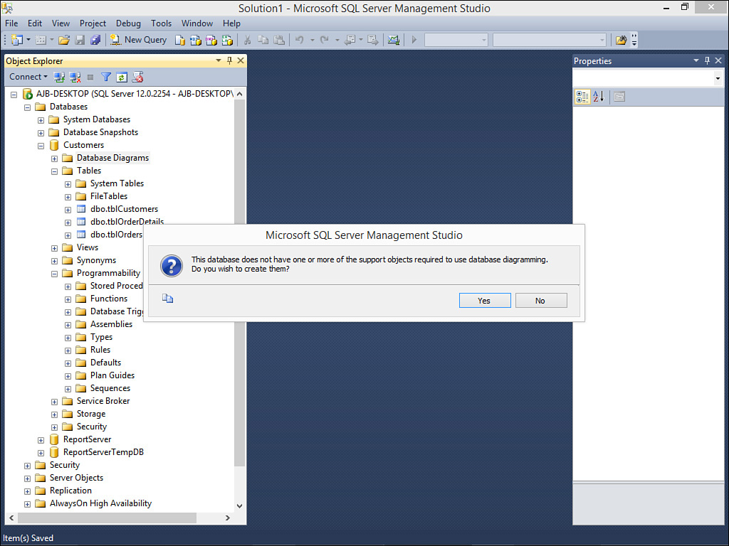
FIGURE 5.1 If you haven’t yet created any database diagrams for a database, you are prompted as to whether you want to create one.
2. Click Yes to proceed. The Add Table dialog box opens (see Figure 5.2).

FIGURE 5.2 In the Add Table dialog box, you select the tables you want to include in the database diagram.
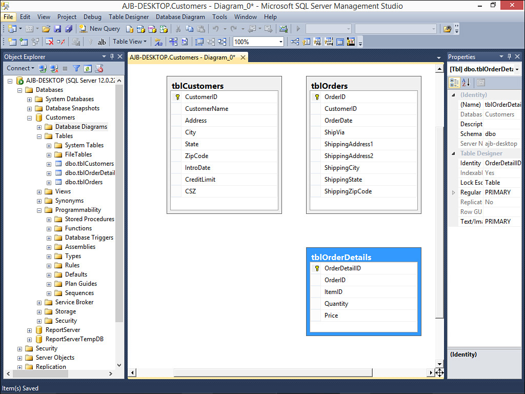
3. Designate the tables you want to add to the database diagram and click Add. Click Close. The diagram appears as in Figure 5.3.
4. Click and drag from the field(s) in the Primary Key table that you want to relate to the field(s) in the Foreign Key table. The Tables and Columns dialog box displays (see Figure 5.4).
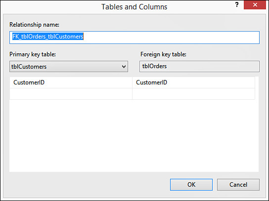
FIGURE 5.4 In the Tables and Columns dialog box, you designate which tables and columns will participate in the relationship.
5. Provide a relationship name and verify that the desired relationship has been established. Click OK to close the dialog box. The Foreign Key Relationship dialog box opens (see Figure 5.5).
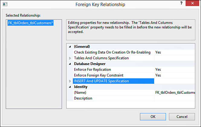
FIGURE 5.5 The Foreign Key Relationship dialog box enables you to designate properties for the relationship.
6. This dialog box contains several important options, which are covered throughout the remainder of the lesson. Designate any properties for the relationship and click OK. You are returned to the database diagram.
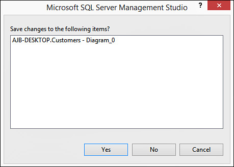
7. When you close the database diagram, SQL Server first prompts you as to whether you want to save your changes (see Figure 5.6). Click Yes to commit the changes to the underlying tables. The Choose Name dialog box displays.
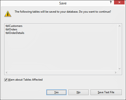
8. Enter a name for the database diagram and click OK. The Save dialog box lets you know which tables you will affect (see Figure 5.7). Click Yes to proceed and update the designated tables. The database diagram should now appear under the Database Diagrams node of SQL Server Management Studio.
To edit a database diagram, you must first open it:
1. If you just created the database diagram and it does not appear in the list of existing database diagrams, right-click the Database Diagrams node and select Refresh.
2. After the diagram appears, right-click the diagram and select Modify. The Relationships dialog box appears.
To edit the relationship between two tables in a database diagram:
1. Right-click a table in the database diagram whose relationships you want to modify and select Relationships (see Figure 5.8). The Foreign Key Relationships dialog box opens (see Figure 5.9).
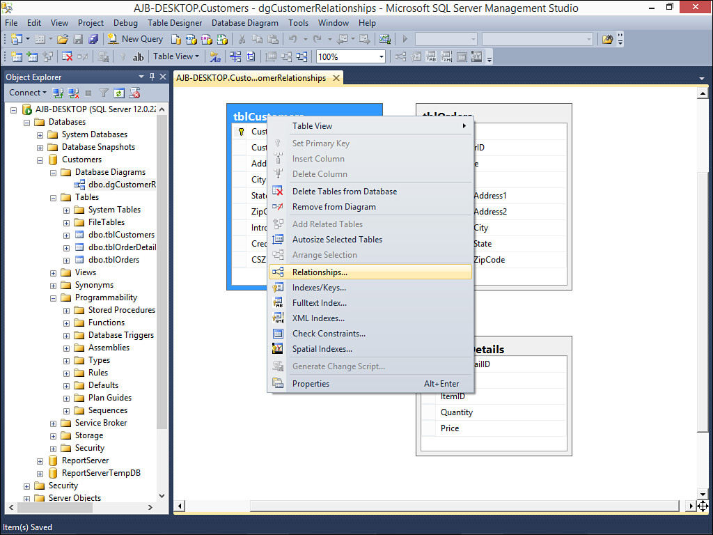
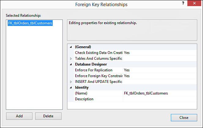
FIGURE 5.9 In the Foreign Key Relationships dialog box, you indicate the relationship you want to modify.
2. Click to select the relationship you want to modify.
3. Modify any of the desired properties (the remaining sections in this lesson cover these properties in detail).
4. Click Close.
Adding Tables to a Database Diagram
To add tables to the database diagram:
1. Right-click anywhere in the Relationships window and select Add Table. The Add Table dialog box opens.
2. Select the tables you want to add to the diagram and click Add.
3. Click Close. SQL Server adds the requested tables to the diagram.
1. Right-click the table you want to remove and select Remove from Diagram.
2. It is important to note that SQL Server removes the table from the diagram but does not remove the relationship from the database.
Note
It is important to understand the correlation between the database diagram and the actual relationships you have established within the database. A database can contain multiple database diagrams. Each database diagram lets you view and modify the existing relationships. When you establish relationships, SQL Server creates the actual relationship between the tables. You can delete the tables from the database diagram (by right-clicking and selecting Remove Table from Diagram), but the relationships still exist (permanently removing relationships is covered in the section, “Deleting a Foreign Key Relationship,” later in this lesson). The Database Diagram window provides a visual blueprint of the relationships you have established. If you modify the layout of the diagram by moving around tables, adding tables to the diagram, or removing tables from the diagram without changing any relationships, SQL Server still prompts you to save the changes to the diagram when you close the diagram window. In that case, SQL Server is not asking whether you want to save the relationships you have established; it is simply asking whether you want to save the visual layout of the window.
Working with Table Relationships
It is easy to view all the foreign key relationships in which a table is participating. Follow these steps:
1. Right-click the table and select Design. The design of the table appears (see Figure 5.10).

FIGURE 5.10 While the design of the table is visible, you are able to select the Relationships tool on the toolbar.
2. Click the Relationships tool on the toolbar. You then see the Foreign Key Relationships dialog box (see Figure 5.11).
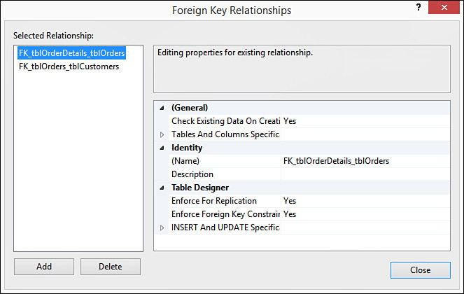
FIGURE 5.11 The Foreign Key Relationships dialog box enables you to work with the relationships associated with a table.
3. Click a relationship to select it. The properties of that relationship appear.
Adding a Foreign Key Relationship
With the Foreign Key Relationships dialog box, you can also add an index. Simply click the Add button. A new relationship appears with a default name and without a description. Before you take any further action, you should supply the Tables and Columns Specification covered in the section “Designating Table and Column Specifications.” You must designate the table and column specification before SQL Server will accept the new relationship.
Deleting a Foreign Key Relationship
Deleting a foreign key relationship is easy. Follow these steps:
1. While in the Foreign Key Relationships dialog box, select the relationship you want to remove.
2. Click the Delete button. SQL Server removes the relationship without warning.
Warning
When you remove a foreign key relationship, you are removing the data integrity protection it affords you. This means, for example, that after you have removed the foreign key relationship between customers and orders, the user can add orders for customers that do not exist.
Designating Table and Column Specifications
By entering a Tables and Columns specification, you designate the foreign key table that will participate in the relationship, the field in the foreign key table that will participate in the relationship, and the field in the current table that will participate in the relationship. To work with the Tables and Columns Specification, follow these steps:
1. In the Foreign Key Relationships dialog box, click the right arrow to expand the Tables and Columns Specification property.
2. Click the Build button (…) that appears to the right of the Tables and Columns Specification property. The Tables and Columns dialog box opens (see Figure 5.12).
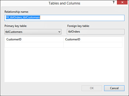
FIGURE 5.12 The Tables and Columns dialog box, showing the relationship between the Customers table and the Orders table.
3. If you want, modify the relationship name. You generally want to rename the relationship to more accurately reflect the relationship you are creating (for example, FK_tblOrders_tblCustomers).
4. Click to select the primary key table that will participate in the relationship. For example, if you are creating foreign keys for the Orders table, you would designate the Customer table as the primary key table.
5. Use the drop-down on the left (under the primary key table) to select the field(s) that will participate in the relationship. For example, in the foreign key relationship between Orders and Customers, the CustomerID in the Customers table participates in the relationship.
6. Use the drop-down on the right (under the foreign key table) to select the field(s) in the current table that will participate in the relationship. In the relationship between the Orders table and the Customers table, the foreign key field participating in the relationship would be the CustomerID field.
7. Click OK to complete the process. SQL Server returns you to the Foreign Key Relationships dialog box.
Adding a Relationship Name and Description
It is helpful to provide a descriptive name for each relationship you add, as well as a brief description. This way when you are viewing a relationship in the Foreign Key Relationships dialog box, you can easily see the nature of the relationship you have selected.
To enter or change a name for the relationship, simply click the (Name) property for the relationship. Enter or change the name as you desire.
To enter a description for the relationship, click the Description property for the index. Enter a short description of your choice.
Determining When Foreign Key Relationships Constrain the Data Entered in a Column
As you can see establishing a relationship is quite easy. Establishing the right kind of relationship is a little more difficult. When you attempt to establish a relationship between two tables, SQL Server makes some decisions based on a few predefined factors:
![]() It establishes a one-to-many relationship if one of the related fields is a primary key or has a unique index.
It establishes a one-to-many relationship if one of the related fields is a primary key or has a unique index.
![]() It establishes a one-to-one relationship if both the related fields are primary keys or have unique indexes.
It establishes a one-to-one relationship if both the related fields are primary keys or have unique indexes.
![]() It cannot create a relationship if neither of the related fields is a primary key and neither has a unique index.
It cannot create a relationship if neither of the related fields is a primary key and neither has a unique index.
As covered earlier in this lesson, referential integrity consists of a series of rules that SQL Server applies to ensure that the relationships between tables are maintained properly. At the most basic level, referential integrity rules prevent the creation of orphan records in the table on the many side of the one-to-many relationship. After establishing a relationship between a Customers table and an Orders table, for example, all orders in the Orders table must be related to a particular customer in the Customers table. Before you can establish referential integrity between two tables, the following conditions must be met:
![]() The matching field on the one side of the relationship must be a primary key field or must have a unique index.
The matching field on the one side of the relationship must be a primary key field or must have a unique index.
![]() The matching fields must have the same data types. They also must have the same size. Number fields on both sides of the relationship must have the same size (
The matching fields must have the same data types. They also must have the same size. Number fields on both sides of the relationship must have the same size (int, for example).
![]() Both tables must be part of the same database.
Both tables must be part of the same database.
![]() If you opt to set the Check Existing Data on Creation option to Yes, existing data within the two tables cannot violate any referential integrity rules. All orders in the Orders table must relate to existing customers in the Customers table, for example.
If you opt to set the Check Existing Data on Creation option to Yes, existing data within the two tables cannot violate any referential integrity rules. All orders in the Orders table must relate to existing customers in the Customers table, for example.
After you establish referential integrity between two tables, SQL Server applies the following rules:
![]() You cannot enter a value in the foreign key of the related table that does not exist in the primary key of the primary table. For example, you cannot enter a value in the CustomerID field of the Orders table that does not exist in the CustomerID field of the Customers table.
You cannot enter a value in the foreign key of the related table that does not exist in the primary key of the primary table. For example, you cannot enter a value in the CustomerID field of the Orders table that does not exist in the CustomerID field of the Customers table.
![]() You cannot delete a record from the primary table if corresponding records exist in the related table. For example, you cannot delete a customer from the Customers table if related records exist in the Orders table (records with the same value in the CustomerID field) unless you designate a Delete Rule (see the section that follows).
You cannot delete a record from the primary table if corresponding records exist in the related table. For example, you cannot delete a customer from the Customers table if related records exist in the Orders table (records with the same value in the CustomerID field) unless you designate a Delete Rule (see the section that follows).
![]() You cannot change the value of a primary key on the one side of a relationship if corresponding records exist in the related table. For example, you cannot change the value in the CustomerID field of the Customers table if corresponding orders exist in the Orders table unless you designate an Update rule in the Foreign Key Relationships dialog box for the relationship (see the “Designating Insert and Update Specifications” section that follows).
You cannot change the value of a primary key on the one side of a relationship if corresponding records exist in the related table. For example, you cannot change the value in the CustomerID field of the Customers table if corresponding orders exist in the Orders table unless you designate an Update rule in the Foreign Key Relationships dialog box for the relationship (see the “Designating Insert and Update Specifications” section that follows).
If any of the previous three rules is violated and referential integrity is being enforced between the tables, an appropriate error message is displayed, as shown in Figure 5.13.

SQL Server’s default behavior is to prohibit the deletion of parent records that have associated child records and to prohibit the change of a primary key value of a parent record when that parent has associated child records. You can override these restrictions by using the INSERT and UPDATE specification, covered in the next section.
For now, let’s see how you can establish referential integrity between the tables in your database. The process is as follows:
1. From the Foreign Key Relationships dialog box, select the relationship for which you want to establish referential integrity.
2. Set the Enforce Foreign Key Constraint property to Yes. This step alone is all you need to establish referential integrity.
3. If you want to check existing data when you save your changes to ensure that they do not violate the referential integrity rules, set the Check Existing Data on Creation or Re-enabling option to Yes.
4. If you are utilizing replication and want to enforce referential integrity during the synchronization process, set the Enforce for Replication property to Yes.
Designating Insert and Update Specifications
SQL Server enables you to define rules that dictate what will happen when the user deletes or updates a record. You can find these rules under the INSERT and UPDATE Specification node of the Foreign Key Relationships dialog box. The text that follows explores this node and why and how you should use it.
The Delete Rule
By setting the Delete rule, you determine what happens when the user deletes a record on the one side of a one-to-many relationship. For example, by setting the Delete rule to Cascade, you establish the rule so that the user can delete a record on the one side of a one-to-many relationship, even if related records exist in the table on the many side of the relationship. The user can delete a customer even if the customer has existing orders, for example. Referential integrity is maintained between the tables because SQL Server automatically deletes all related records in the child table.
If you attempt to delete a record from the table on the one side of a one-to-many relationship and no related records exist in the table on the many side of the relationship, you are able to delete the record. On the other hand, if you attempt to delete a record from the table on the one side of a one-to-many relationship and related records exist in the child table, you will delete the record from the parent table as well as any related records in the child table.
Tip
Setting the Delete rule to Cascade is not always appropriate. It is an excellent feature, but you should use it prudently. Although it is usually appropriate to cascade delete from an Orders table to an Order Details table, for example, it generally is not appropriate to cascade delete from a Customers table to an Orders table. This is because you generally do not want all your order history deleted from the Orders table if for some reason you want to delete a customer. Deleting the order history causes important information, such as your profit and loss history, to change. It therefore is appropriate to prohibit this type of deletion and handle the customer in some other way, such as marking him as inactive or archiving his data. On the other hand, if you delete an order because it was canceled, you probably want the corresponding order detail information to be removed as well. In this case, the Cascade option is appropriate. You need to make the appropriate decision in each situation based on business needs. The important thing is to carefully consider the implications of each option before making your decision.
The Update Rule
With the Update rule set to Cascade, the user can change the primary key value of the record on the one side of the relationship. When the user makes an attempt to modify the field joining the two tables on the one side of the relationship, the change is cascaded down to the foreign key field on the many side of the relationship. This is useful if the primary key field is modifiable. For example, a purchase number on a purchase order master record may be updateable. If the user modifies the purchase order number of the parent record, you would want to cascade the change to the associated detail records in the purchase order detail table.
Note
There is no need to select the Cascade option when the related field on the one side of the relationship is an identity field. An identity field can never be modified. The Cascade option has no effect on identity fields.
Note
Other options for the Delete and Update rules include No Action, Set Null, and Set Default. No Action, the default value, does nothing and therefore does not allow the deletion of parent records that have children or the modification of the key field(s) of parent records that have children. Set Null sets the value of the foreign key field to Null. Finally, Set Default sets the value of the foreign key field to its default value.
Summary
Even if your table design is sound, a database set up without proper relationships compromises both data integrity and application performance. It is therefore important that you establish the proper relationships between the tables in your database. This lesson began with a discussion of the types of relationships available. You then learned about important topics such as how to establish relationships, how to designate table and column specifications, how to determine when foreign key relationships constrain the data entered in a column, and how to designate INSERT and UPDATE specifications.
Q&A
Q. What is the Tables and Columns specification?
A. The Tables and Columns specification enables you to designate the foreign key table that will participate in the relationship, the field in the foreign key table that will participate in the relationship, and the field in the current table that will participate in the relationship.
Q. Describe three uses of a one-to-one relationship.
A. You use a one-to-one join when the number of fields required for a table exceeds the number of fields allowed in a SQL Server table, when certain fields that are included in a table need to be much more secure than other fields included in the same table or when several fields in a table are required for only a subset of records in the table.
Q. Describe a many-to-many relationship and how you create one.
A. With a many-to-many relationship, records in both tables have matching records in the other table. You cannot create a many-to-many relationship directly. You must develop a junction table and relate the junction table to each of the two tables in one-to-many relationships.
Workshop
Quiz
1. Name the three types of relationships.
2. What is the most common type of relationship?
3. To create a relationship, matching fields must have the same data type (true/false).
4. By setting the Delete rule to Cascade, when a user deletes a row on the one side of the relationship, SQL Server deletes the corresponding rows on the many side of the relationship (true/false).
5. The UPDATE rule is very useful when working with Identity columns (true/false).
6. List three advantages of establishing relationships between database tables.
Quiz Answers
1. One-to-one, one-to-many, and many-to-many.
2. One-to-many.
3. True.
4. True.
5. False. Because you cannot change the value of an identity column, the UPDATE rule is not applicable to an identity column.
6. Data integrity, optimal performance, and ease of use in designing system objects.
Activities
Create a table that will store order information. Add a field called OrderID that will be the primary key field of the table. Make its data type Int and make it an identity field. Add a field called CustomerID. Give it the data type of Int. Add a Not Null constraint to the field. Add a field called OrderDate. Make it a DateTime field. Add another field called ShippedBy. Make it an Int field. Finally, add a field called FreightAmount. Make it a Money field. Now that you have created the table, establish a relationship between it and the Customers table created in Lesson 4, “Working with SQL Server Tables.” Base the relationship on the CustomerID field from each table. Make sure you set the Enforce Foreign Key Constraint property of the relationship to Yes. Add some customers to the Customers table. Make note of their CustomerIDs. Add orders to the Orders table for those customers. You should be able to add those orders without a problem. Try adding orders for customers that do not exist. You should not be able to do so because of the referential integrity you applied. Try deleting customers who have orders. Once again, you should fail because of referential integrity. If you are feeling really ambitious, set the Delete Rule of the relationship to Cascade. Then try deleting a Customer with orders. The process should delete the customer and its corresponding orders.