Chapter 8. Troubleshooting Call Routing
Call routing is one of the most important features for any private branch exchange (PBX), whether it is traditional or IP-based. It is the call-routing functionality that enables the users of a communication system to place calls. The system can then route those calls to the appropriate destination-based available routing information. This gives rise to the possibility for a number of issues related to call routing. Those call-routing issues may stem from any of a number of potential causes. They can be associated with Cisco Unified Communications Manager (CUCM) call flow configuration, bandwidth, network infrastructure, quality of service (QoS) settings, and any number of potential variables. This chapter dives into single-site and multisite call-routing troubleshooting because the methodology is largely the same, regardless of where the call is destined or how it is routed. The key aspects are somewhat identical in terms of what to check and how to configure or reconfigure to make the system work.
Chapter Objectives
Upon completing this chapter, you will be able to
• Troubleshoot Cisco Unified Communications Manager (CUCM) call setup issues
• Complete a dial plan review focusing on partitions and calling search spaces
• Troubleshoot on-net calling issues
• Troubleshoot off-net calling issues
• Troubleshoot one-way calling issues
• Troubleshoot call-forwarding issues
• Troubleshoot MGCP gateway issues
• Troubleshoot H.323 gateway issues
• Troubleshoot Cisco Unified Border Element (CUBE) issues
Cisco Unified Communications Manager Call Setup Issues
A number of issues can arise even with the most simple actions such as placing a call between two IP phones. The amount of infrastructure, underlying technology, configuration, and other considerations underlying the seemingly simple task can be daunting. These issues present themselves in a variety of manners, depending on the conditions that caused them. The most common issues experienced include the following
• Fast-busy signal
• Missing or incorrect caller ID
• No ringback
• Dead air
• One-way audio/video
• Inefficient call routing
• Unexpected secondary dial tone
The fast-busy signal tends to be one of the least favorite sounds in all of telephony. That is, of course, when it is actually due to a problem rather than a misdialed number. The important thing in diagnosing a fast-busy signal is when it occurs. Does it occur while the number is being dialed? Or, does it happen after the final digit is pressed? If it’s after the final digit, is the fast-busy immediate, or does it take a few seconds to occur after the final digit? Each of these questions is important in deciding where to begin troubleshooting.
When the fast-busy occurs while the digits are being dialed, digit-by-digit analysis has determined that there is no matching route pattern within the calling search space. So, the fast-busy means either that a user has misdialed a number or a route pattern is missing but needed. Fixing this issue entails making sure the user is dialing the number correctly, with the correct access code and prefix. Also, make sure that the user’s class of service (CoS) allows the dialing of the pattern in question. If those things are in order, the creation of a new route pattern may be in order.
When the fast-busy occurs after the digits have been dialed, there is most likely an available route pattern, but the trunk/route list referenced by the route pattern is unavailable. Keep in mind also that the prior scenario could also be in play. If the digit-by-digit analysis failed to find a match only after the last digit was dialed, the fast-busy is heard. In such cases, the Dialed Number Analyzer is your friend in terms of troubleshooting the cause of the dial failure.
A missing or incorrect caller ID is quite common for inbound and outbound public switched telephone network (PSTN) calls, internal calls, and more. The calling-party number can be manipulated in numerous places within the CUCM configuration, including the line-level External Number Mask, the calling-party transform field on route patterns and route lists. Inbound calls from the PSTN may experience issues if the provider isn’t sending the calling-party number information or automatic number identification (ANI) inbound along with the call setup. It may well be that caller ID is a service that must be ordered and provisioned on the PSTN trunks. If the feature wasn’t ordered, it may be stripped before the call hits the PSTN ingress gateway.
Ringback tone is what a caller hears when digits are dialed. The cadence of the ring or silence in the ringback tone varies by country. It generally matches the cadence of the ring of the destination phone itself. At times, however, it isn’t heard. Sometimes this is intentional. Other times, it is indicative of a problem (which may or may not be within your realm of control). Most often, lack of ringback tone is experienced when a call is being transferred (such as a supervised transfer). For a blind transfer, there may well be a ringback tone. PSTN calls should always have a ringback tone accompanying the call setup. In some cases, the ringback tone is omitted if the locales of source and destination cannot be determined or there is some other telco-related issue.
At times, when a call is placed and answered, one or both sides hear silence. This essentially means that the signaling was successful, but the media streams could not be established. This could be due to a network issue, such as improper QoS, or it could be due to a codec mismatch. That is, the region configurations of the phones do not have a codec in common. Another common indication of codec mismatch is seen when a call is placed, the destination phone rings, and then, when the call is answered, it drops immediately. In such situations, it is not uncommon to hear, “It’s a codec moment.”
Assuming the call is answered and stays up, sometimes the media stream is able to establish itself in only one direction. Remember, media traffic is User Datagram Protocol (UDP) based. Each UDP datagram is routed based on its own merits. It is not always going to be like a Transmission Control Protocol (TCP) session in which the entire flow takes the same pathway. So, it is feasible for audio and/or video to be established in one direction while the other direction fails to pass the media stream properly. This is most often a network-related issue. Usually, it comes down to the QoS configuration somewhere in the call path.
Call routing within the network is a science, bordering on art in some instances. Call routing involves dial plan. It involves network reachability. It involves QoS configuration to protect the traffic flows for signaling and media. The underlying architecture is just as important as the logic utilized in deciding how calls will route both within and without. When users roam between company sites, things can get difficult. When those sites cross geographical borders, the situation can get even more problematic and interesting. How do we maintain a logical, sane dial plan and minimize or eliminate users having to change dialing behaviors as they roam about the planet? Do we build the intelligence into the dial plan or force per site/per country training on the user community? There are no easy answers. However, it is agreed that a user based in Texas should not be using the voice gateway in Texas when he or she has traveled to London. Call-routing efficiencies such as these are somewhat common sense. But, not all call-routing methodologies and decisions are so clear-cut. Efficient call routing maximizes the user experience while minimizing required effort necessary to support it.
In a traditional PBX environment, dialing 9 or 0 to access an outside line provided a secondary dial tone by virtue of the fact that the 9 or 0 was actually a trunk access code. In a CUCM environment, or any Internet Protocol (IP) PBX for that matter, the secondary dial tone is merely there because that is what people expect to hear when they dial that access code. In fact, every bit of feedback heard when using home or office phones is there as a creature comfort. The sounds let the user know that something is going on. White noise is generated on the line simply so that there is a lack of utter silence. There is no need for the noise from a technical perspective. People tend to get uncomfortable, or think something is broken, when utter silence is on the line. It is a form of validation, “Are you there? Can you hear me? The line went quiet.” Ringback tone is another creature comfort. It’s not required for the system to function. The secondary dial tone has been relegated to this creature comfort category as well. In the CUCM realm, it’s only there to let you know that a route pattern has been found based on the dialed digits.
It is important to understand that the secondary dial tone is generated only when the check box on the route pattern is ticked and that route pattern is a match for the digits dialed. Consider the route pattern details in Table 8-1.
Table 8-1. Route Patterns and Outside Dial Tone

The first appears to be a PSTN destination, but it is actually the direct inward dial (DID) block assigned to the company by the telephone company. The 408-555-XXXX numbers are all internal and really don’t need to be utilizing PSTN trunk resources. So, the number is translated to XXXX. The second route pattern is indeed a PSTN destination. In fact, it’s a US long-distance PSTN route pattern. The route pattern is configured to provide a secondary dial tone and to discard the leading 9. Assuming both patterns are within the calling search space of the calling party, the system has to make a decision. Both patterns match when 914085551234 is dialed. However, at what point can the system truly make the decision as to which route pattern to use? Call routing is done based on the most explicit match for the route pattern in question. So, it is able to figure out that 9.14085551234 should be processed against the translation pattern. That translation pattern is not set to provide an outside dial tone. So, none is heard. What about when another number is dialed within the 408 area code—for example, 9.14087774321? The 9.1408 still matches. So, up to that point, the system can’t know for certain whether or not to play the outside dial tone. So, it doesn’t. Once 914087 is dialed, it has a definitive match and the secondary dial tone is heard. However, remember the creature comforts? Users expect to hear an outside dial tone right after pressing the access code to seize an outside line. This is a case in which the users may need a bit of retraining.
These are just a few of the things that can show up in the day-to-day operation of a Cisco collaboration deployment. If you want to fully understand and troubleshoot these issues, and others that may arise, it is crucial that you have a firm understanding of dial plan operation and best practice.
Dial Plan Review
Few aspects of a collaboration deployment have the potential to be as misunderstood or reach the complexity level of the dial plan. Within a single site containing a single cluster, the dial plan tends to be relatively simple. Moving toward a multisite, multicluster, or international deployment can bring in variables that would make even the most seasoned collaboration engineer’s head spin. While at least a basic understanding of dial planning is assumed by the time you reach this point, it is prudent to bring the most important elements back to mind to facilitate a troubleshooting discussion.
The dial plan is a key element of the Cisco collaboration solution deployment. It is responsible for instructing the call processing agent (CUCM) on how to route calls and includes the following:
• Endpoint addressing (phone number and/or Session Initiation Protocol [SIP] Uniform Resource Identifiers [URI])
• Path selection
• Calling privileges (CoS)
• Manipulation of dialed digits
• Presentation of information about the calling and called parties
Endpoint addressing can be numeric or alphanumeric (using URIs). Numeric addresses are represented by a sequence of digits. No special structure is assumed by the call processing agent. It merely interprets the digits based on the best match against the information it has been provided in the call-routing table. All numeric dialing destinations for registered endpoints, voice-mail ports, and the like, as well as alphanumeric destinations (directory URIs) configured in CUCM, are added to the internal call-routing table as explicit patterns. Alphanumeric addresses take the form of [email protected]. There is a user-specific portion as well as a domain-specific portion. Domain Name Service (DNS) lookup for SIP service records (SRV) resolves the necessary destination information, whether it is internal or external.
Regardless of whether numeric, alphanumeric, or more likely, both addresses, are in use, they are handled through the use of partitions and calling search spaces. The partition and calling search spaces combine to decide on path selection, CoS, how digits are manipulated, and how information about calling and called parties is presented.
Partitions
There have been many discussions surrounding the definition of, and purpose for, partitions. Many texts have settled on the idea that a partition is a group of numbers with the same reachability. This is true. However, it is not really a simplified version of the definition. There is still the question of what is “the same reachability”? The simplest definition comes down to this: a partition is a bucket of numbers.
When a number is dialed, the search for a match to the dialed digits is performed against the numbers in that bucket. Of course, the search for the dialed digits can be performed across multiple buckets. That list of buckets to be examined is the calling search space (CSS), which is examined shortly.
The bucket is important in terms of defining the directory number (DN). The DN is a coupling of the actual assigned number and the partition. Even if there is no partition, there is a partition. The null partition <None> is used when no partition has been assigned.
Note
Do not use the null, <None>, partition in a production environment. It opens the dial plan to a number of security and toll-fraud-related possibilities that most companies simply wish to avoid.
So, when the definition of partitions states something obscure, such as “a group of numbers with the same reachability,” it really means a bunch of numbers in the same bucket. Partitions are assigned to call-routing targets, which include
• DNs
• Route patterns
• Translation patterns
• Voice-mail ports
• Pilot numbers
• Hunt group pilots
• MeetMe conferencing numbers
When you’re using directory URIs, a partition is assigned as an alias to it. Typically, it is assigned the same partition as that in which the phones are placed. To call a directory URI, the directory URI alias partition must be in the calling search space of the calling party.
The dial plan entries within a partition may include a number of entities, such as these:
• DNs
• Directory URIs
• Translation patterns
• Route patterns
• CTI route points
• Voice-mail ports
If two identical patterns are an equal match for a dialed pattern, CUCM selects the one that was encountered first in the CSS. Of course, those identical patterns need to be the closest match to what was dialed. Directory URIs are a bit different; they must match completely. There is no concept of a partial match with them.
Calling Search Spaces
The calling search space (CSS) is a list of partitions (buckets) to be searched when a number is dialed. There are numerous types of CSS within CUCM, and each has a particular purpose in mind. CSS types include the following:
• Line CSS
• Device CSS
• Gateway inbound CSS
• Rerouting CSS
• Subscribe CSS
• Automated alternate routing (AAR) CSS
• Calling-party transform CSS
• Called-party transform CSS
From the perspective of a Cisco IP Phone, the line and device CSS concatenate to create the CoS (aka class of restriction, CoR), which dictates the patterns it is allowed to call. If both are configured, as is usually the case, the CSS of the line from which the call is generated is considered first and then that on the device level. The effective CSS is the combined list of buckets to be searched by the line- and device-level CSSs. In a line/device dial plan, explicit denials are implemented at the line level, and PSTN or site-specific (gateway selection) routing is done at the device level. This keeps the CoS separate from gateway selection so that users can roam about the network without the need to change dialing behavior, and to maintain restrictions regardless of the site to which users roam. Line/device dial planning is examined later in this chapter.
A device can call only those patterns that are designated within its CSS through a permit or deny (allow or block) circumstance. A CSS can be assigned to any entity that can generate a call-routing request. In the end, the device calls only those call-routing patterns permitted in the combined CSS.
CUCM Call Routing
Dial plan design is an immensely important and potentially equally complex process. The design prior to deployment can make or break a dial plan. One of the most common mistakes in dial plan design is the lack of forward-looking vision. Many collaboration engineers know the system and how it operates. However, the longevity and impact of the decisions made today will be around for a long time to come. Countless expansions, optimizations, refreshes, and more will be undertaken from the network perspective. Building a dial plan is not like building an IP addressing scheme. The dial plan has an impact far beyond any one element of the network, or the call control implementation. Dial plans are long lived. They become so entrenched in the business that they cannot be altered without great pain from the user community. Where a four-digit dial plan fits today, a five- or seven-digit dial plan may be needed down the line. Making a change such as that is almost impossible in most environments. What you put in place today will likely still be in effect decades from now. Will they be singing praises of your foresight or cursing your lack of looking beyond install day?
With all of this in mind, we will offer a number of considerations throughout this book with regard to dial planning. They include some common-sense items as well as things you may not have taken into account.
Do not use the null (or <None>) partition, as mentioned earlier. We cannot emphasize this point enough. Will phones ring and calls route using the null partition? Sure. But anything in the null partition is always accessible, regardless of CSS or other CoS considerations. Think of it as a “permit any” equivalent in some respects. It represents a way to subvert the CoS within the network. There is also a null CSS. It too is represented by <None>. Entities assigned to the <None> CSS can access only other entities within the <None> partition.
Recall that a CSS is an ordered list of partitions. The order in which the partitions appear within a CSS represents the order in which they are processed. So, high-priority partitions need to be placed higher in the CSS list. Multiple identical entities (route patterns) can exist within a CSS, but they must be in different partitions. If no single best match exists (such as longest or most explicit match), the call-routing table entry with the partition listed first in the CSS is used to route the call.
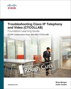
What constitutes a longest or most explicit match? What makes a route pattern more explicit than another? What does each represent in terms of numeric matching and explicitness? Consider the route patterns in Table 8-2.
Table 8-2. Route Pattern Processing
Now, consider the concept of a longest (or best) match. The most explicit is the pattern with the fewest possible matches. If the dialed digits are 1234, the result for most explicit match is obviously 1234. What about when the dialed digits are 1235? Which patterns match 1235? All but the last one, 1234. Among the remaining possibilities, which is the longest match? It is easy to rule out XXXX and 1XXX because 1[12]XX is more explicit than either of them. Also, 12XX is yet more explicit than 1[12]XX because the route contains an explicit digit rather than a wildcard definition. Following that line of logic, which is more explicit, X or [345]? X represents a value of a digit between 0 and 9. So, [345] is more explicit a match than X. That being the case, 12[345]X wins out over 12XX. But 123X is another explicit digit match, which means it wins over the [345] wildcard. Figure 8-1 shows a more simplified version of call-routing logic in CUCM.
Figure 8-1. CUCM Call-routing Logic Illustrated

Figure 8-1 is not meant to confuse you. The idea is to get your mind used to looking at route patterns and determining which is the longest or most explicit match in terms of digits versus wildcards. Figure 8-1 is based on the dialed digits; the most explicit route is chosen for each scenario. Note that 22XX points to a gateway. That is actually a rather common configuration when connecting to a legacy time division multiplexing (TDM) PBX. The users want to keep their same extensions when they are migrated away from the old PBX onto the new CUCM. Because every endpoint’s DN is added as an explicit route in CUCM’s routing table, 22XX is fine to point to the remaining phones. As each phone is migrated over, a new route is added by virtue of configuring a phone with the migrated DN.
When 1235 is dialed, the most explicit route pattern in Table 8-2 is 123X. However, what if there are two matches for 123X in the routing table? Which one is chosen? The one in the partition listed first in the CSS. So, the order of the partitions is very important within the CSS.
We’re not saying that there are not potential pitfalls when the routing table has multiple matches. Overlapping patterns result in post-dial delays if the digits are received one-by-one. There is a way to avoid this issue if you know there is an overlap. On each route pattern or translation pattern, there is an option to check a box for urgent priority. If the pattern matches, go with it immediately. Don’t wait for interdigit timeouts or other input.
Without the urgent priority box checked, CUCM waits for the interdigit timeout to expire. This is typically 15 seconds, by default. Users are not happy if they dial numbers and then have to wait 15 seconds for the call to proceed. In most environments today, users run out of patience long before the 15 seconds expire. They’ll hang up and try the call again, only to get the same results. Then they’ll likely be calling you with a trouble ticket. Rather than understanding the concept of an interdigit timeout, the user perceives the issue as a call failure. Frustration ensues.
To avoid this problem, implement the dial plan in a manner that avoids any overlapping route patterns. When this is not possible, configure the more prevalent route pattern with the urgent priority flag set.
Sometimes a route pattern has additional potential matches if more digits are received. This often happens in environments that have implemented variable-length dial plans. Variable-length dial plans occur mostly as an evolutionary trait. The company began with a four-digit dial plan and is converting to five-digit. Consider a case in which the company’s DID range is +1-408-555-XXXX. In converting from four- to five-digit dialing, the company goes from XXXX to 5XXXX. What happens when a user dials another user at extension 5123? If there are registered phones with DNs in the range of 5123X, the system has a difficult time telling the difference. So, it waits for the interdigit timeout. Remember when we posed the question, “Will they be singing praises of your foresight or cursing your lack of looking beyond install day?” This is the point at which they will be cursing your lack of foresight.
How can you avoid all the ire? Using E.164 numbering format throughout the dial plan is one way to ensure that the dial plan has the flexibility it needs to grow without significant pain. That means that the dial plan must be constructed in a manner that supports + dialing.
+ Dialing in Route Patterns
Use of the + in dialing has long been a cause of instant fear and loathing. The concept might seem confusing, but it’s not overly difficult. The amount of time it saves in the long run is significant. It also provides a good way to avoid the dreaded “edit dial” requirement to place a callback to a number in your phone’s call history.
Recall that numeric addresses are simply a string of digits. ITU recommendation E.164 introduced a standard format for the structure of globally unique numeric addresses (phone numbers) to be used in the PSTN. Figure 8-2 shows the format for E.164 numbers.
Figure 8-2. E.164 Format for Geographical Numbers

In Figure 8-2, designations need to be defined. Table 8-3 shows these designations.

Table 8-4 shows some detail in terms of country context for some E.164 address formatting. Without the context, it’s difficult to understand the function of each component.
Table 8-4. E.164 Number Comparison

The entire E.164 number may include only 15 digits. This doesn’t include any access codes required to dial it, however (for example 0, 011.). The country code is exactly what it seems—a code specific to the country in which the destination phone exists. The National Significant Number (NSN) is composed of the National Destination Code (NDC) and the subscriber number (SN). In the United States, the NDC is the area code, and the SN is the user’s seven-digit phone number.
In countries such as Germany, the dial plan can get a bit interesting. This is especially true when the number of digits varies based on destination. The country code does not change, but the NDC and/or SN can vary. For a user in the United States to dial the number 49 69 1234 1234, the dialed digits are typically 9011496912341234. That is a lot of digits. The 011 is an exit code for international numbers dialed from the United States and Canada. Of course, 49 is the German country code, and 69 is the area code (NDC) for Frankfurt. The SN of the phone is 12341234. There are a couple of additional rules, of course. The SN is between 5 and 11 digits unless the destination is a cell phone, which needs to be 10 or 11 digits.
Utilizing a full E.164 dial plan eases the pain associated with international dialing and provides a high degree of flexibility in terms of what is possible in the enterprise dial plan.
So, the user can simply dial +496912341234 (to dial + on most Cisco IP Phones, you hold down the * key). The back-end dial plan takes care of the rest. Of course, the back-end dial plan does take considerable work to implement.
Addressing Methods in CUCM
Interestingly, there are a few ways to dial Cisco IP Phones. You can take the handset off-hook and dial, as is the traditional method. However, you can also leave the handset on the cradle and dial the digits. Picking up the handset, pressing the speakerphone button, or pressing the Dial softkey takes the phone off-hook and places the call. Many never really consider that there are differences in how the CUCM analyzes digits based on how the call is dialed. This can also be the case based on the type of phone and line-side protocol in use. Table 8-5 shows these variations in digit processing.
Table 8-5. Addressing Methods in CUCM

When you look at Table 8-5, there seems to be a good amount of information to remember. That is certainly the case. The documentation on Skinny Client Control Protocol (SCCP) dialing is rather vague. It generally says that every key press is sent to CUCM. Based on research and sniffer traces, this is the case only when the phone is in the off-hook state. When it’s on-hook, the digits are sent en bloc to CUCM. So, when a phone is on-hook and a user dials 1235, realizes he meant to dial 1234, presses the << key once, dials 4 (1235-delete-4 = 1234), and then presses the Dial softkey, the CUCM receives only 1234. It doesn’t get the 5 or the delete. Dialing the same pattern with the phone off-hook results in a key press event for all events, 1235<<4.
SIP phones tend to be a bit more complicated. They have undergone an immense amount of evolution over recent years. They can operate with or without SIP dial rules. SIP dial rules change the way SIP dial processing is done. The reason is that they are stored on the phone itself. With that in mind, you should be concerned with two types: type A and type B.
Type A SIP phones are the older handsets—7905, 7912, 7940/7960 running SIP firmware, for example. A Type A SIP phone without dial rules sends the dialed digits en bloc to CUCM in a SIP INVITE message. If the phone is on-hook, you need to press the dial softkey or go off-hook. If the phone is already off-hook when the digits are dialed, you must press the dial softkey or wait for the interdigit timeout. SIP dial rules allow the phone to essentially mimic the capabilities of the SCCP phone. So, the digits can be processed as they are pressed. With a SIP dial rule in place that matches a dialed pattern, the call proceeds immediately on match with no need to press dial or wait for the interdigit timeout. When the phone recognizes the pattern, it sends that pattern en bloc via a SIP INVITE.
Type B SIP phones include the 79x1, 79x2, 7975, and newer handsets. Late-generation 7940 and 7960 handsets could also be Type B phones. These handsets act like SCCP by default. Without SIP dial rules, they utilize Keypad Markup Language (KPML) within SIP NOTIFY messages for digit-by-digit analysis. This assumes the phone is off-hook when dialing is taking place. If it’s on-hook while dialing, you are back to using the SIP INVITE for an en bloc digit sending methodology. SIP dial rules effectively force the Type B phone to revert to Type A. The SIP dial rules are processed locally first. This means that there cannot be a digit-by-digit analysis (that is, no KPML). When a match is found, the SIP INVITE is sent to CUCM with the en bloc digits. If no match is found to the SIP dial rules, you have to go back to pressing the dial button or waiting for the interdigit timeout.
Device/Line CSS Approach to Dial Plan
Among the most misunderstood concepts in Cisco collaboration is dial planning. The concept of how partitions and CSSs interact is rather intricate at times. Adding to the confusion, the so-called best practice dial plan has evolved greatly over time. Where you used to create per site partitions and calling search spaces to implement CoS, the process has been somewhat simplified and streamlined. The same restrictions are possible with around one-third of the configuration effort. Think of it in reverse from the way it was done in the CUCM 4.x days.
CoS can be applied in a number of ways. Often, what are commonly referred to as “evolved dial plans” have only a device-level CSS and no line-level CSS. This represents a missed opportunity and a sure sign that more time has been devoted to CoS than is necessary.
When the CSS is applied only to the device, it encompasses all lines on the device. That may not always be the desired result. In a single-site environment, the traditional approach is fine. However, it doesn’t scale well. The traditional approach results in way too many calling search spaces and partitions. It also tends to make calling among sites more difficult than it needs to be. It comes down to just how badly you wish to create an entire dial plan per site. For a small number of sites, this approach may work. For a large number of sites, a more streamlined approach is needed. That approach is the device/line dial plan.
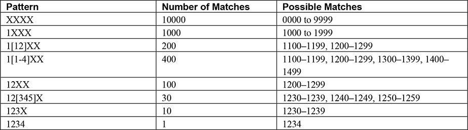
In terms of call processing, CSSs are processed in a particular order. In fact, everything is processed in a particular order. Figure 8-3 shows how the CSS for a given device is processed.
In Figure 8-3, the line and device CSS are visible. The processing for dialed patterns takes both into account. So, they essentially combine to form a single CSS. The line is processed first. If blocks are encountered, they are enforced whether or not they are permitted at the device level. In the device/line dial plan, the explicit blocks are instituted at the line level, and then everything else is allowed. The device-level CSS includes PSTN and other site-specific route patterns. This allows extension mobility, Cisco Unified Mobility, and other features to function easily. Because nothing changes at the device level, gateway selection is not an issue when users roam. There are numerous other benefits from a dial plan perspective.
Because only explicit blocks are implemented at the line level, enterprisewide, the blocks need to be created only once. In the traditional dial planning methodology, the dial plan permit and deny patterns were created per site. If you had 30 sites, you created 30 sets of partitions, calling search spaces and translation patterns. In the device/line dial plan, you create one set of blocks for the enterprise.
You create the blocks by using translation patterns in a block partition with the Block This Pattern option selected. Figure 8-4 shows the Translation Pattern Configuration page.
Figure 8-4. Translation Pattern Configuration Page

In Figure 8-4, a long-distance block is shown. When added to the line-level CSS, the US long-distance route patterns are blocked entirely. Similar blocks can be added for local, international, toll-fraud, and other route patterns and applied to the line-level CSS.
Using this method, employ the device CSS to provide site-specific patterns, gateway selection, and more to the device. The device CSSs are unrestricted because the line CSS has already implemented the CoS and blocked unauthorized patterns.
On most call sources, such as gateways, trunks, and the like, only one CSS can be configured, the inbound CSS. This should be considered to be from the perspective of the gateway or trunk. When an inbound call hits, the inbound CSS determines where the call can be routed. The inbound CSS should include internal numbers and other patterns that inbound callers may need to reach. The effective CSS is not a combination of multiple CSSs. It’s simply one CSS. So, it’s prudent to create a gateway or trunk inbound CSS specifically to process calls for those entities.
It is worth noting that CTI ports process a bit differently. They are configured as pseudo device/line entities. But they process line and device CSSs in reverse order. The partitions of the device are placed above those of the line in the priority order.
Since CUCM 7.x, it hasn’t really been necessary to add a device-level CSS to perform gateway selection. The addition of the local route group took care of that. The local route group is selected at the device pool level. So, devices in a particular device pool use the specified gateway regardless of the line configuration.
Time of Day Routing
One implementation of partitions and calling search spaces allows for time of day (ToD) routing. The basic premise is that calls to one destination are routed in different directions based on the time of day or day of the week. A specific schedule is created for times during which specific patterns are allowed to be called and those times in which they are not. During allowed times, the phones ring. During nonallowed times, they forward straight to voice mail, for example. ToD routing is used to route calls differently based on time in the following manner:
• Identical route patterns are created and put into different partitions.
• At least one of these partitions has a time schedule applied.
• If the partition with the time schedule is listed first in the CSSs, it takes precedence over other partitions while it is associated with the partition.
• If the current time does not match the configured time schedule, the partition that has the time schedule assigned is ignored, and the next partition becomes the partition with highest priority.
Time of day routing tends to be misunderstood because of the way it has to be configured. The three main components to the configuration are
• Time Periods: Specify time and day of the week ranges
• Time Schedules: Specify a group of time periods
• Partitions: Contain DNs made subject to a time schedule
The time period defines the open or closed times and days of the week on which those times are valid. Where most configurations falter is in the understanding that a time period needs to be configured for the period of between midnight and the beginning of business hours, and then another for the closed time period between closure and midnight. So, it takes multiple time periods to make a closed schedule. For some businesses with no weekend hours, there is an additional time period for full weekend closure.
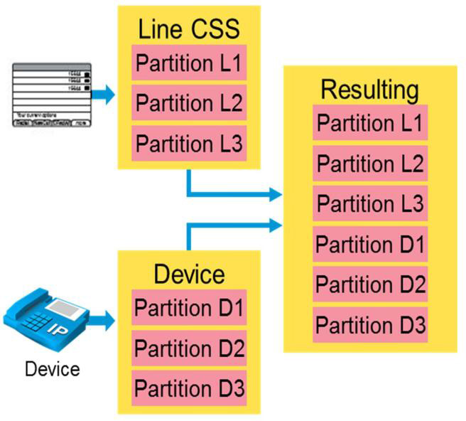
It is worth adding to this discussion that it is not required to have an open time period or time schedule. The phones already have DNs in a particular partition that can be called anytime. Create the closed schedule and place it first in the CSS so that it’s processed first. In practice, creating a specific open partition has the effect of blocking internal calls during the closed periods. That is rarely the desired outcome. The reason is that the DNs to be subject to the ToD routing must be placed in a partition active only during those hours. Typically, during closed hours, calls to DNs in the closed partition are sent directly to voice mail. Figure 8-5 shows the morning closed hours time period.
Figure 8-5. Time Period Information Page
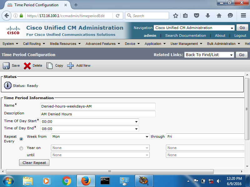
Figure 8-5 shows the same days of the week along with the hours 00:00 to 08:00. This is the time period the business is closed between midnight and 8:00 a.m. Figure 8-6 shows the time period for the evening during which the business is closed.
Figure 8-6. Time Period Information Page, Continued

Figure 8-6 shows the same days of the week. However, the hours are set from 17:00 to 24:00. Finally, the weekends must be addressed. Figure 8-7 shows the weekend closed hours time period.
Figure 8-7. Time Period Information Page, Continued

In Figure 8-7, the days are set from Saturday to Sunday. Take notice of the order of the days in the drop-down list. They begin with Sunday and go to Saturday. Don’t define this period as Sunday to Saturday unless you really mean it. Saturday to Sunday defines the period desired for this example. Also, notice that no hours are set. Instead, No Office Hours is selected.
With all the relevant open and closed time periods defined, it’s time to actually sort them into open and closed. You do this with the time schedule. Figure 8-8 shows the closed schedule configuration.
Figure 8-8. Time Schedule Configuration Page

In Figure 8-8, all three closed time periods are selected and added to the time schedule. This brings all the time periods together into a single, cohesive closed schedule.
With the time periods and time schedules defined, you now need to create the partitions. When you’re creating a partition, there is an option to associate a time schedule with it.
Create a partition for the open time schedule. Figure 8-9 shows the partition in use for the closed schedule.
Figure 8-9. Partition for Time of Day Routing

Again, the recurring theme here is the use of meaningful, descriptive names and relevant descriptions. Make the configuration easy to follow for those who may be trying to trace call flows or troubleshoot. Figure 8-9 shows the partition, pt-closed-schedule, with the Deny-Calls-During-Business-Hours Time Schedule selected.
With the time periods, time schedules, and partitions all created and associated, you need to get them into production. That is the most important aspect; it depends on the implementation objective.
If the objective is to block calls to phones outside of business hours, add the relevant phone DNs to this partition. Those DNs should be configured to forward all calls to voice mail (check all the boxes in the Voice Mail column). This partition is seen as a valid choice for the DNs within it only during the hours specified within the time schedule. If it is invalid due to the times, it is skipped.
To subject the DNs to the schedule for inbound PSTN calls, you should place the newly created partition with closed hours into the gateway inbound CSS as the first entry. That is where the inbound calls are processed against those partitions. If there is some pressing reason that it cannot be the first entry, just make sure it is processed before the partition in which the rest of the phones are located. Because that partition doesn’t have a schedule, it can be called at any time from the inside. If the newly created closed partition is below it, the schedule will never be utilized.
This type of configuration is often used for schools. Teachers’ DNs are subject to the closed schedule during school hours and opened otherwise. However, they can be called during the day from any phone inside the network.
If the objective is to limit the ability to dial certain patterns during certain time periods, such as blocking all international calls on the weekend, that is easily done. Figure 8-10 shows an example of this in practice.
Figure 8-10. Time of Day Routing Example

Figure 8-10 shows an example of ToD routing blocking international calls on weekends and on January 1. During nonweekend days, and days other than January 1, the partition with the blocking time schedule is invalid. However, it is in the top of the relevant CSS(s). First, you create a route pattern that allows international calls. The route pattern is put into the standard partition, which has no time schedule applied.
A second, identical route pattern is created and is placed into the Weekend partition. Then a time period is configured for Saturday to Sunday 00:00 to 24:00. Another time period is configured with a specified date: January 1. These two time periods are put into a time schedule, and the time schedule is assigned to the Weekend partition.
The phones throughout the enterprise are assigned with a CSS that contains the Weekend partition first, followed by the Standard partition. Additionally, route patterns and translation patterns can be configured with the parameter Block This Pattern to deny the call if the pattern is selected by the call-routing logic (best match, earlier listed partition).
Users are able to dial international calls at any time during a weekday (Monday through Friday) because the Weekend partition is not active (based on the Standard partition). Because the route pattern that is in the Weekend partition is configured to block the call, international calls are not possible whenever the Weekend partition is active (because it is listed before the Standard partition in the CSS of the phones). The Weekend partition is active on weekends and on January 1.
On-Net Calling Issues
At the beginning of this chapter, we touched on a few common issues that occur. The following sections focus on some of the issues that can arise with on-net calling in both single-site and multisite Cisco collaboration deployments. The troubleshooting methodologies are slightly different depending on the topological layout of the underlying internetwork, how it is deployed, available resources, and so on.
Single-Site Call Setup Issues
When calls fail within a single-site deployment, the quantity of potential culprits tends to be smaller than those in multisite deployments. In single-site deployments, the considerations most often focus on endpoint-specific configuration and CUCM settings that are applicable to all devices. Calling issues may arise out of incorrectly implemented CoS or a missing or incorrect CSS on the line or device.
In terms of the general settings that may affect a large concentration of devices or cause call failure, improper digit manipulation and/or an invalid destination may be to blame. Invalid destinations may occur due to a lack of a route pattern to a dialed destination, an unregistered device, misdialed numbers, and more.
In a single-site deployment, typically, all devices are registered to a single call control cluster, possibly even a single CUCM node. This call control has the full view of all known on-net destinations. When an endpoint, a user, or an application dials a destination, CUCM easily determines whether the destination is on-net or off-net.
If the dialed destination is determined to be off-net, CUCM needs to select an egress point, typically a gateway. This egress gateway is specified in the route pattern matching the dialed destination. If only one gateway exists, this may be a simple decision. If multiple options are available, it can become more complex. Multiple factors go into selecting the egress route, such as
• Call initiator
• Dialed destination
• Resource availability
• Resource prioritization
To be able to select the proper egress point based on the dialed digits, CUCM must know and classify the destination. But what if the dialed destination does not consist of numbers, but alphanumeric values? What then? How does call processing work there? Are the rules the same? These are real, valid questions in any collaboration deployment. SIP URIs are taking over and must be taken into account.
Recall that E.164 numbers have a hierarchical structure based largely on geography. E.164 addresses, like most other addresses, are less explicit (or significant) on the left. They become more explicit or user-specific moving toward the right side. Egress point selection for E.164 destinations may be based on a prefix-based routing scheme that attempts to choose the egress point nearest the destination. This limits the amount of distance the call must traverse using an external provider. This is often known as a tail-end hop off (TEHO). This kind of routing is not legal in all countries. So, you should exercise caution when building such an architecture. Sometimes political issues get in the way of efficiency.
SIP URIs look like an e-mail address in that they employ a [email protected] type of format. There is a user portion on the left-hand side (LHS) of the @ and a host (or domain) portion on the right-hand side (RHS). Where E.164 has a clear hierarchy, SIP URIs allow some hierarchy only in the host portion (RHS) of the URI. This is typically the domain name. However, subdomains can be specified and DNS SRVs resolved to geographically diverse resources based on the destination domain/subdomain. However, this does not provide a great deal of granularity in geographical terms. This is especially true if a flat URI scheme (for example, mydomain.org instead of sjc.mydomain.org and rtp.mydomain.org) was utilized in the overall design. Unlike E.164 and many other addresses, the most significant piece of a SIP URI is on the right, with the user-specific portion being on the left.
Improper Digit Manipulation
Digit manipulation is an art form, to be sure. Because the digits for both the called and calling parties can be modified in so many places, it can become quite confusing. It only takes a misconfiguration in one of these places to cause chaos in a dial plan.
Digit manipulation can be either implicit or explicit. Implicit manipulation implies that it is done as part of call routing through the use of a translation pattern, route pattern, or route list. Explicit manipulation implies that it occurs after routing has taken place. That is, it occurs on the incoming calling- or called-party gateway configuration settings, trunks, or device pools; the calling/called-party transformation CSS on gateways, trunks, or device pools; or the calling/called-party CSS on endpoints. As call processing takes place, digit manipulation occurs in a specific order:
1. Translation pattern
2. Route pattern
3. Route groups in route lists
4. Gateway transformation CSS
The manipulations that take place at the route pattern, route group/route list, and gateway are all completely independent of each other. So, a manipulation occurring at the route pattern can be overridden by the route group/route list, which can, in turn, be overridden by the gateway. So, the order of precedence increases as the call moves toward the egress gateway.
It is not uncommon for confusion to ensue when this order of precedence is not understood. Keep the order of processing in mind and work your way through the call flow when troubleshooting. Often, it’s most effective to draw out the call flow and show the digit manipulation that occurs at each step of the process to understand how, why, and where calls may be failing.
Unknown or Unregistered Destination
To route a call to a destination, the destination must be in the call-routing table. If the call is off-net, an egress point is required. If it’s on-net, the destination must still be known.
When an endpoint is registered with CUCM, an explicit route is entered into the call-routing table with the DN(s) assigned to the device. As long as the device is registered, the route remains valid. If the device unregisters, for whatever reason, that route becomes invalid. If no phone number is listed in the Call Forward Unregistered field in the phone’s configuration, there is no valid destination. If the Call Forward Unregistered number is not formatted correctly or is invalid for some other reason, again the call fails.
When a route pattern does exist to the destination, there must be available resources to support the egress of the call. There has to be available calling capacity on the egress trunk.
CoS Configuration
Class of service is an exceedingly common reason for call failure. Many times, this is by design. When a user dials a number that he or she is not authorized to dial, you want the call to fail. If the call is to a destination that the user should be able to dial, it is time to investigate. The CoS of an endpoint is determined based on the combined CSS of the line and the device. This determines what route patterns are available to be dialed from a specific line on that device. The CoS for an inbound call is determined by the inbound CSS on the ingress interface or trunk. If the inbound CSS doesn’t include a partition that contains a match for the called-party number, or Dialed Number Identification Service (DNIS), the call fails.
Gateway Configuration
Gateway configuration can actually match any of the preceding possibilities. Recall that digit manipulation at the gateway level takes precedence over other implicit digit manipulation. If Media Gateway Control Protocol (MGCP) is used as the gateway protocol, it can become unregistered, thereby causing destinations to become unreachable for inbound and outbound calls. If the inbound CSS is improperly set or improperly configured, calls coming into the network may be routed incorrectly or blocked altogether.
The gateway is vital because it is the final touch point for outbound calls and the first for inbound calls. The gateway configuration can have a dramatic impact on the ability for calls to pass in and out of the network.
Multisite Call Setup Issues
Any of the things that occur in a single-site deployment can also occur in a multisite deployment. Of course, the reverse is true, depending on the degree of configuration similarity. As you move into multisite configurations, issues of media resources, WAN bandwidth, codec selection, and others are added to the aspects that can plague the single-site deployment.
In larger deployments, more call control nodes may be utilized within a single cluster, or the deployment may expand on to multiple clusters, super-clusters, or mega-clusters. Each cluster represents a single call control entity composed of multiple call processing units. Additional services are included along with call control. This includes Trivial File Transfer Protocol (TFTP) servers, music on hold (MoH) servers, and other media resources. Each cluster is an independent entity in control of the resources at its disposal (registered resources), gateways, trunks, and more.
In such an environment, the on-net versus off-net decision may become clouded. In collaboration deployments of such size, selecting the correct internal or external connection for a given call, on- or off-net, comes down to the dial plan and routing scheme. In such an environment, E.164 routing becomes key to maintaining order and ensuring a complete lack of any dial plan overlap among the various clusters.
The key decisions are not really all that much different from the single site. In fact, the same requirements exist for call setup:
• Call initiator
• Dialed destination
• Resource availability
• Resource prioritization
The difference is now that the destination may not be a PSTN or a truly external destination. It may be a destination on another cluster. It can be an on-net resource or destination registered to another cluster. Such a dial plan will almost assuredly include the implementation of a prefix routing scheme similar, if not identical, to the E.164 hierarchy. This greatly simplifies intercluster routing because each cluster only needs to really understand the relevant prefixes associated with each of the other clusters in the architecture. Essentially, it’s an equivalent of a summary route in an IP network in terms of routing between autonomous systems.
With numeric addressing and strict geographical distribution of endpoints to each of the clusters in the environment, route selection becomes somewhat more streamlined. Routing decisions become based on specific prefixes and ranges of phone numbers local to each of the call control clusters. A given local cluster need only know the in-depth dial plan of the endpoints under its control. It need only understand the prefixes that will allow it to route calls to its peer clusters. Figure 8-11 shows an example of prefix routing in use.
Figure 8-11. Multisite Prefix Routing

Each of the clusters in Figure 8-11 only needs a prefix route for the blocks of numbers in the other cluster. Each has its own PSTN routes, of course. So, outbound calling will function. The prefix routes match the PSTN route pattern, but they are a longer match than the PSTN route pattern. Therefore, intercluster calling takes the on-net path as long as there is capacity (for example, it is allowed by CAC and the path is available).
Hierarchical routing can easily be performed with prefix routing. It can also be done with the URI architecture. The prefix equivalent in a SIP URI architecture is accomplished via a domain hierarchy. You can implement routing based on either the host or domain portion of the URI. Using a subdomain architecture makes on-net calling significantly easier in large environments. Each cluster is assigned a subdomain for purposes of URI routing. CUCM needs SIP routes to be put in place to route the subdomains between clusters. Figure 8-12 shows an example of subdomain routing.
Figure 8-12. Multisite URI Routing
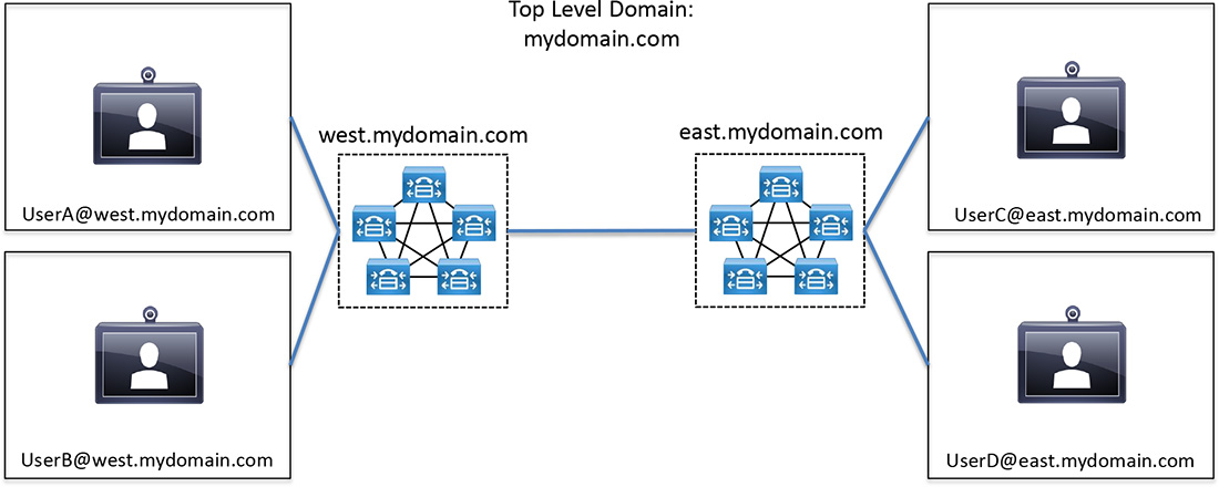
In Figure 8-12, the two clusters are each assigned a subdomain based on geographical location. The designation can be whatever fits your needs. Also, note that the URIs include capital letters. By default, CUCM is case sensitive when dealing with URIs. This is configurable in the Cisco CallManager Service Parameters. But it is important to understand that [email protected] is a different SIP URI than [email protected] while that service parameter is set to case sensitive. If that is not the desired setting, change it to case insensitive.
Sometimes subdomains are simply not feasible, or a flat network was implemented before the idea of subdomains was presented. Whatever the case, it is more difficult but can be manageable. In this kind of environment, each of the clusters still needs to know about the URIs hosted on each. Global Dial Plan Replication (GDPR) provides the capability for the clusters to exchange information about URIs local to each.
Understanding the underlying dial plan architecture is key to not only building and administering a Cisco collaboration deployment but also to troubleshooting. Many of the issues are identical to single-site deployments.
Call capacity between sites is a key element to understanding the big picture. CUCM contains the capability to protect voice/video calls from being overrun by other voice/video calls. This feature is called connection admission control (CAC). The basic premise is that a specific amount of bandwidth is allowed to be utilized by calls between given locations. The amount of bandwidth is based on the codec in use and the total number of calls that can be safely supported (and QoS protected) between sites. These locations are defined in CUCM. When the specified bandwidth between the sites is entirely utilized, allowing an additional call to set up endangers the quality of all calls by creating a congestive condition. So, CUCM denies that call from setting up. It may use automated alternate routing (AAR) to route across the PSTN rather than remaining on-net. In the absence of AAR, the call is rejected in favor of protecting the existing call volume.
Improper Digit Manipulation
Digit manipulation can occur at a number of times during (implicit) and after (explicit) call routing. Recall that, as call processing takes place, digit manipulation occurs in a specific order:
1. Translation pattern
2. Route pattern
3. Route groups in route lists
4. Gateway transformation CSS
Also remember that the routing at steps 2, 3, and 4 are entirely independent of each other. It is important to remember these things in a multisite deployment because there is a potential for a larger impact. When you are using prefix routing, the idea is to keep an on-net call on-net. This includes keeping it on-net even when it’s dialed as an off-net destination would be. Consider Figure 8-13. It’s the same picture from the prefix routing discussion.
Figure 8-13. Multisite Prefix Routing, Revisited

In this type of environment, translation patterns might be utilized to implement a forced on-net routing architecture. That is, when a user from the left cluster dials 912125551234 to reach a user in the right cluster, forced on-net utilizes a translation pattern (configured in the left cluster) to alter the dialed pattern so that it is sent on-net rather than via the PSTN. The PSTN route is utilized only if the on-net route is unavailable for whatever reason.
Improperly configuring the translation pattern (implicit digit manipulation) may cause the call to fail altogether, worst case, or ignore the translation pattern and progress off-net, best case. So, you must take care in constructing the per-destination digit manipulation that may be necessary to keep costs down and avoid toll fraud within the environment.
Unknown or Unregistered Destination
Unknown or unregistered destinations may have a varied impact on dialing. Like any condition, it depends on the conditions at hand. For unknown destinations, one or both clusters would be missing required destination information regarding the dialed digits. In some cases, one cluster might have a route that forwards it to the other cluster, which has no route. So, the call dies anyway. Troubleshooting these types of situations can be intricate. Within a single cluster, the Dialed Number Analyzer provides an end-to-end path of the call flow—that is, from its origin until it exits the cluster’s sphere of control. When it hits the other cluster, the Dialed Number Analyzer can be used again. For the first cluster, the call is analyzed from the perspective of the phone. On the second cluster, it might be analyzed from the perspective of the ingress gateway.
An unregistered destination has the same impact as the unknown. However, a destination that was registered and is now no longer registered can be treated somewhat differently if there is a Call Forward Unregistered (CFU) destination added on the line level. This tells CUCM how to route the call while the original destination device is unavailable. If the CFU is not configured, the call fails.
Lack of Necessary Media Resources
Media resources are a necessary component of any collaboration deployment, whether it is single or multisite. Media resources include the following:
• Annunciator Resources
• MoH Resources
• Conference Bridge (CFB) Resources
• Media Termination Point (MTP) Resources
• Transcoding (XCode) Resources
Figure 8-14 shows the CCMAdmin page with the Media Resources tab expanded.
Figure 8-14. CUCM Media Resources Tab

Not all these resources are used in every deployment. The annunciator is the resource that places messages such as “Your call cannot be completed as dialed.” It is essentially the voice of CUCM. It uses SCCP and the Cisco Media Streaming Application service. Its core function is to enable CUCM to play prerecorded announcements and tones to phones and gateways. The annunciator can also play tones for some transferred calls and some conference calls.
MoH services are considered to be vital in any collaboration deployment. MoH can be provided using unicast or multicast traffic. Multiple servers and audio streams can be offered. There are two essential audio sources in use by endpoints and gateways. These are the User Hold MoH Audio Source and the Network Hold MoH Audio Source. When a user is on a phone call and places that call on hold, the person on the other end of the call is played the MoH specified in the User Hold MoH Audio Source. When a user is on a call and transfers the call to another user, the Network Hold MoH Audio Source is played. There are rules and configuration considerations, certainly. MoH has become an art form all its own.
Conference bridge (CFB) resources can be provided by CUCM as a software service or by a hardware conference bridge such as a Cisco IOS router with digital signal processor (DSP) resources allocated to the CFB purpose. These resources are used when users initiate ad hoc or MeetMe conferences. They are also utilized when making a supervised transfer of a call in progress.
MTP resources are utilized to allow CUCM to relay calls that are routed through SIP or H.323 endpoints or gateways. Like the annunciator, MTP relies on the Cisco IP Voice Media Streaming App service being activated and running.
Transcoders are resources that convert the media streams between the two disparate codecs to enable communications between them.
Media resources are defined in Media Resource Groups (MRG). Generally, hardware resources are added to their own groups, software resources to their own groups, and so on. Sometimes they are mixed (single site, for example). In some instances, all that exist are the software resources. The MRGs are placed into a Media Resource Group List (MRGL). The order in which they are placed is the order in which they are invoked for a given type of resource. The order of resources within the MRG is irrelevant. The resources within the MRG are used in round-robin fashion. The MRGL, however, utilizes the MRGs in the order in which they are placed within the list.
Codec Mismatch Between Endpoints
A codec is a coder-decoder. It provides the means by which the spoken word is converted to packetized voice. In single-site deployments, the G.711 (64k PCM) codec is generally used. If bandwidth allows, G.722 might be used for high-quality wideband audio. In lower-bandwidth environments, G.729a (24k CSA-CELP) might be utilized. For two phones to communicate, they must be using the same codec. When the two phones are separated by a WAN, it may not be feasible for G.711 to be used, due to bandwidth consumption. So, G.729a is the more common choice for lower-speed links. If one phone is set for only G.711 and the other only for G.729a, they have a codec mismatch and cannot communicate. That is, they cannot communicate without a transcoder in place to convert between the codecs. Codec selection is managed by the Region configuration and assigned in the device pool.
Also worth mentioning, in a codec mismatch scenario, MoH can be played using various available codecs. If a mismatch occurs between the phone to receive the music stream and the MoH codec, the music does not play. An MoH codec mismatch is somewhat more difficult to chase down than a codec mismatch between two phones.
When a call is placed between two phones that have a codec mismatch, the destination phone typically rings and then drops the call upon being answered. Another possibility is that the destination phone rings once and then drops the call. The codec mismatch may be due to misconfiguration within the Regions or lack of available DSP resources on the transcoder.
CoS Configuration
When you are dealing with multisite, multicluster environments, the CoS configuration can be a bit more difficult to design, comprehend, and troubleshoot. In a multisite environment within a single cluster, it’s somewhat less involved to troubleshoot simply due to the fact that call control is under the preview of that single cluster. Bringing multiple clusters into the mix means there are multiple call control entities providing the combined CoS, impacting the call path.
When a user dials a destination, the line and device CSSs combine to allow CUCM to decide whether that number is authorized. Once it is deemed allowed, is there a route, a resource, and an egress point? If the egress is via a trunk to another cluster, the other cluster has to go through the same process beginning with the inbound CSS on the trunk through which the call is ingressing. If the number is allowed, is there a route, a resource, and an endpoint or egress point?
The CoS configuration has a dramatic impact on the user experience for those users with phones in each site and each cluster.
Clustering over WAN
Clustering over WAN (CoW) has long been the subject of significant discussion. CoW is usually implemented when a remote site performs business-critical functions that make it a prudent decision to provide it with local call control. This means placing one or more CUCM subscribers at the site to perform call control functions for the phones within the site. This is called the Remote Failover Deployment Model, and it is not without its ramifications. The bandwidth involved with cluster replication is not insignificant. Design considerations must take into account not only the attributes of the wide area network link itself, but also the traffic types that pass between the CUCM servers themselves. One-way delay must not exceed 40 ms (80 ms round trip). This calculates out to a maximum distance guideline of around 6,000 km (3,720 miles).
QoS is crucial. Intra-Cluster Communication Signaling (ICCS) between CUCM servers consists of a number of types of traffic, some of which should be classified as DSCP 24/PHB CS3, whereas other types should be DSCP 0/PHB BE. This has to be done to minimize latency and jitter and to guarantee bandwidth.
QoS
Gone are the days when basic queuing, compression, or a big, fat pipe was sufficient to be able to avoid QoS. QoS is not merely queuing. It is the prioritization of traffic on the ingress port, across input buffers, across the processor, across output buffers, and out the egress port. It requires a great deal of design consideration and must be implemented on all routers and switches throughout the network. When deploying collaboration architectures, QoS is not optional. QoS issues across a WAN link may introduce undue latency impacting ICCS traffic, signaling traffic, or media traffic. Packet loss in a voice or video session is significant because retransmission of packets is not an option. Signaling traffic must be protected, as is the case also for media flow traffic. Large amounts of bandwidth are simply not a plausible reason to not deploy QoS.
cRTP
Real-time Transport Protocol (RTP) provides transport for media traffic. It is a connectionless protocol that provides payload type identification, sequence numbering, time stamps, and delivery monitoring. Real-time Transport Control Protocol (RTCP) provides feedback on network conditions and provides an out-of-band control mechanism for an RTP flow. RTP and RTCP open for a given media flow on successive UDP ports. The RTP header is 12 bytes in length. When the voice payload is typically between 20 and 160 bytes, that is a significant amount of overhead. Couple that with the 8-byte UDP header and 20-byte IP header, there is a great deal of overhead associated with transporting media (40 bytes total overhead).
RTP Header Compression (cRTP) is an overhead reduction mechanism for use across WAN links. RTP traffic consists of two UDP flows. Figure 8-15 shows a basic diagram of RTP packets.
Figure 8-15. RTP Packet Structure Without and with cRTP
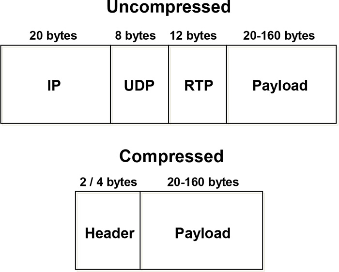
In Figure 8-15, it becomes clear where the benefit lies with cRTP. The 40 bytes of overhead are reduced to 2 or 4 bytes, 2 if no UDP checksums are used or 4 bytes if UDP checksums are used.
However, beware of the consequences. As with any other type of compression, there is a cost. What is gained in bandwidth efficiency comes at the cost of increased latency.
The cRTP configuration on both sides of a point-to-point WAN link must match. If one end is configured with it but the other is not, calls may fail altogether. At the very least, one-way audio results.
Remote Gateway Configuration
At this point, we’ve touched on gateway configuration to some degree. Protocol selection is, of course, key to how the dial plan is arranged and administered. A number of options are available on gateways. A voice gateway has DSPs on board. They can be used as a local media resource for transcoding and conference bridging. Remember, if no transcoding resources are available and codec conversion is required due to a codec mismatch, the call will fail.
The gateway can also be configured to provide backup call control services through configuration of Survivable Remote Site Telephony (SRST). SRST can provide basic call control functionality in the event of a WAN outage that causes CUCM to become unavailable. When the phones miss three keepalives with CUCM, they register to the local SRST reference for calling services. After the CUCM returns, they wait a certain amount of time (defined by the connection monitor duration setting in CUCM) to restore their registration to the CUCM node.
The reason for any WAN outage should, of course, be explored. Is it a provider issue or a local gateway failure or a misconfiguration? A gateway misconfiguration may keep the SRST reference from functioning properly, resulting in a greater outage for the impacted site.
Troubleshooting Call Setup Issues
Although this section focuses on issues discussed thus far, specifically a one-site deployment, the concepts are relevant to single-site, multisite, multicluster, and so on. Troubleshooting these issues all comes down to walking the call flow. The DNA is your friend. Perform the analyses most relevant to the issue at hand. If all else fails, draw it out, step-by-step. Keep the rules in mind: Where is digit manipulation applied? How are the calling search spaces for a given device, whether endpoint or gateway, constructed?
As a thought exercise, consider a simple call failure. A user reports calling another internal DN and gets a reorder tone. What are the relevant questions to ask?
1. At what point in the dialing process did the reorder occur? While still dialing or immediately after dialing?
2. What is the number being dialed?
3. What is the number of the calling-party phone?
Why are these valid or important questions? What does it tell us when the call fails while the digits are being dialed? It says that the digit-by-digit analysis has failed before the entire number was dialed. That is, there is no route in the CSS of the phone doing the dialing. If the call fails after the last digit is dialed, that indicates the CSS processed and found a match, but the route pattern may not have reachability or resources needed to reach the destination. In any event, answering these questions gives you a starting point.
So, start with the Dialed Number Analyzer (DNA), as discussed in Chapter 3, “Using Troubleshooting and Monitoring Tools.” Open it up and run a phone analysis with the source and destination phone numbers. Let it tell you where it’s failing.
If the failure occurred while dialing, check the CSS on the device and line. The DNA will likely show an unallocated number. So, this approach might not be all that helpful. Visually walk the source phone’s combined CSS.
Consider possibilities for all possible cases:
• Are there translation patterns in play? Remember implicit manipulation occurs before the call is routed.
• The destination phone’s partition is missing from the CSS.
• The destination phone is unregistered.
• The dialed number is simply invalid (it happens).
What if there is a translation pattern impacting the call potentially? What are the ramifications? The translation pattern has a CSS too. It may not include the destination phone’s DN partition or may be missing the partition of the transformed called-party number, if that is what was transformed. The DNA shows you the translation pattern in use, if it is invoked in the call flow. So, the output, although it may show an unallocated number, is not completely lacking in information.
It is also possible that a call-routing loop exists, resulting in call failure. These issues are a bit harder to troubleshoot but should be at least partially visible in the DNA.
If the destination phone is unregistered, it obviously doesn’t have a configured Call Forward Unregistered number set, or it is not formatted correctly to dial out to the desired alternate destination.
SCCP Call Setup Flow
In any in-depth troubleshooting scenario, it is very helpful to understand the call setup flow. Figure 8-16 shows a diagram of the setup flow between the calling phone and CUCM.
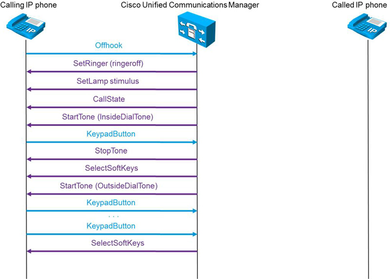
Figure 8-16 shows an exchange by the calling-party phone and the CUCM. The calling phone goes off-hook and sends each event to CUCM, key press by key press in KeypadButton messages. CUCM analyzes the input digit-by-digit against the CSS and call-routing table. In Figure 8-16, the DN of the destination IP phone is matched. Figure 8-17 shows the next phase of the call setup.
Figure 8-17. SCCP Call Setup, Continued

CUCM then notifies the destination phone that there is an inbound call and that it should ring. It also instructs the phone which ringtone to play. When the destination phone goes off-hook, CUCM tells it to turn off its ringer. Figure 8-18 shows the next phase of the call setup.
Figure 8-18. SCCP Call Setup, Continued
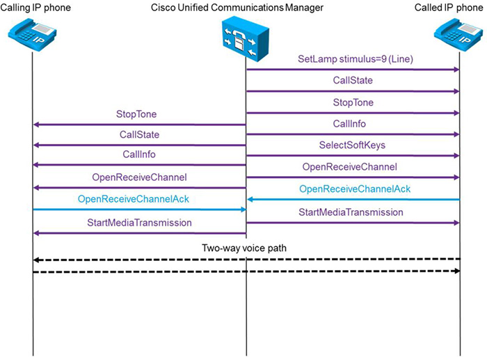
CUCM tells the phone to turn on the line button lamp. Both phones are instructed to update their displays and to stop playing the current tones (ringback [alerting] tone for the calling phone and ringtone for the called phone). CUCM then instructs the phones to begin media exchange using the OpenReceiveChannel and StartMediaTransmission messages. These messages include information regarding the RTP streams, including destination IP address, RTP ports, and codec in use. After the two-way media stream is established, the call setup is complete.
Tracing CSS Problems
Calling search space problems can be difficult to trace, depending on the extent and number of entities in the call flow path. In tracing issues with CSS, you can draw it all out for the end-to-end call. Or you can use the tools at hand just for these types of complex analyses: call traces.
Call traces enable you to troubleshoot calling issues, including call setup, partitions, calling search spaces, and much more. Enable the traces and fire up the Real Time Monitoring Tool (RTMT). The traces you want for CSS problems are going to be generated by enabling detailed traces for the Cisco CallManager service in Cisco Unified Serviceability.
In RTMT, call setup information is displayed in signal distribution layer (SDL) traces. With traces running, place a call from one phone to another. Keep track of the time. There can be a great deal of output in the traces. Reference the time stamps in the debug output to find your specific call. Display the trace file and locate the beginning of events within the time period you recorded for the test call. Figure 8-19 shows an example of a call trace.
Figure 8-19. Tracing CSS Issues

In Figure 8-19, the phone with the number 2002 places a call to 2001. Upon opening the trace file, locate the first event that relates to your call. In the trace, the log shows that the caller with the IP address 10.1.100.58 pressed the NewCall button. As a side note, the trace also shows the TCP handler number assigned to the phone when it registered to CUCM. This number remains with it until it unregisters and uniquely identifies all trace output related to this phone. StationInit messages are always phone to CUCM. StationD messages are always CUCM to phone. The figure shows that the phone goes off-hook at the beginning of the new call. Figure 8-20 shows the continuation of the trace.
Figure 8-20. Tracing CSS Issues

In Figure 8-20, the caller has begun dialing. This triggers digit collection and analysis on CUCM. The digit analysis shows the partitions within the CSS being parsed. Interestingly, the trace output refers to the CSS as a partition search space (pss). When analyzing the trace output, look at the filteredPartitionSearchSpaceString or TodFilteredPss rather than merely the partitionSearchSpace (pss). These pieces contain the partitions used for final CoS processing after applying the time of day configuration, if any. Digit collection and analysis continue until the user dials enough digits to find a match or fail recognition within the CSS. Figure 8-21 shows the continuation of the trace.
Figure 8-21. Tracing CSS Issues, Continued

In Figure 8-21, notice that the dialed digits, 2001, found a match. The calling-party number is shown as the fully qualified calling number (fqcn). The fqcn is the number after applying the external number mask. It’s also shown as the cn, the directory number configured at the phone’s line level. Additionally, the list of partitions searched is shown again. The bottom of the figure shows the message NoPotentialMatchesExist. This should really say that no more potential matches exist. The trace found a unique match and is moving on. Figure 8-22 shows the continuation of the trace.
Figure 8-22. Tracing CSS Issues, Continued
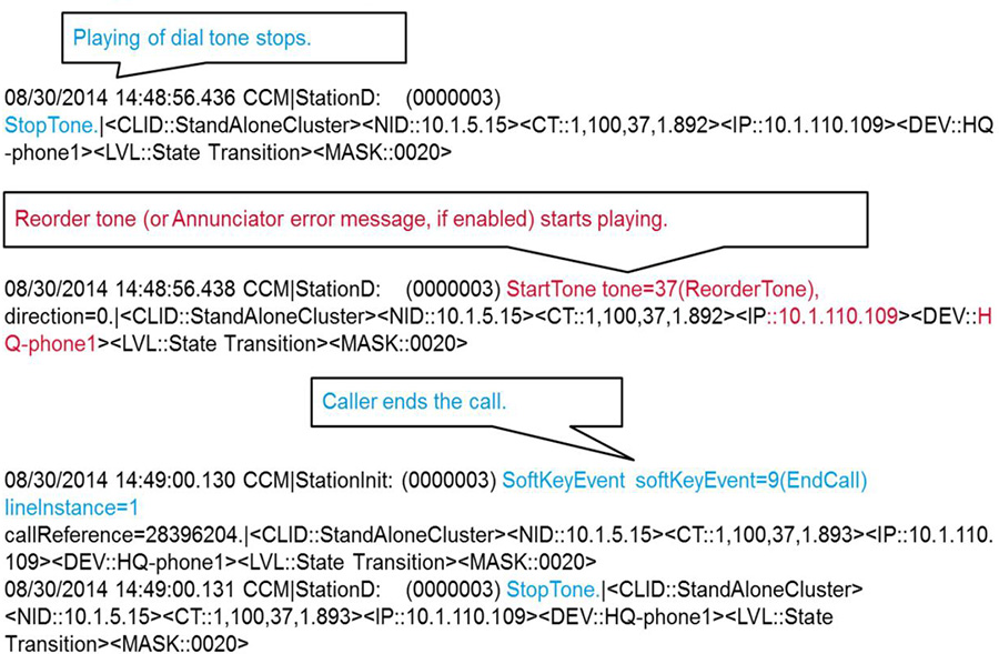
In this part of the trace, notice that the call is being routed and ringback tone is being provided to the calling party while the destination phone is ringing. However, a reorder tone has been played to the caller, and the call setup attempt ends with the user pressing the EndCall softkey on the phone. If the annunciator is enabled, the caller hears a spoken message instead of the reorder tone’s fast-busy sound.
Multisite Dial Plan Issues
Significantly more issues can arise in multisite deployments than in single-site deployments. A distributed call processing environment involves a lot more geography and locations. These locations are connected by any number of possible WAN links at varying speeds. In addition, the PSTN deployment model has a great deal of bearing on the complexity of the overall architecture. The PSTN deployment can be centralized, distributed, or hybrid. The possibilities are virtually endless. Figure 8-23 shows a multisite deployment.
Figure 8-23. Multisite Topology

Figure 8-23 shows two sites: Headquarters and Branch A. Each has an independent CUCM cluster. In addition, each has deployed Expressways C and E to provide VPN-less access to remote users and business-to-business calling.
When a call setup fails in a deployment such as this, consider the settings on the endpoints, the dial plan on both clusters, WAN-related settings/configuration, and of course, QoS configuration.
That seems like quite a bit, certainly, but the settings you need to check are those in the call flow path. When the phone at 2001 dials the phone at 4001, the path is obviously going to be on-net as first preference. However, if the IP WAN is at capacity or experiencing issues, more may be going on than meets the eye.
On the surface, check the usual suspects. Use the DNA to see how the call setup is progressing and egressing. If it’s hitting the intercluster trunk between the CUCM clusters, it should be traversing the network. If it’s not, look for AAR references in the DNA flow. That means the primary path is unavailable for whatever reason. There is digit manipulation going on to prepend digits and route the call across the PSTN. There is a whole new set of CSS entries that are specific to the AAR configuration to check. They operate on the same rules. They just involve a significant amount of digit manipulation, and the user must be allowed to dial the patterns necessary to accomplish that dialing.
Assuming the call egressed the headquarters cluster successfully, it’s time to repeat the DNA on the Branch A cluster. Where the DNA analysis was performed on the phone for the headquarters cluster, it will be done on the ingress gateway for the Branch A cluster. If the call is failing, check the destination endpoint to ensure that it is registered. If it’s not registered, any nonshared line DN on that phone will be unreachable. As mentioned before in this chapter, the inbound CSS on the gateway at Branch A is the most likely suspect in the investigation. It needs to include the partition in which the 4001 DN exists for the call to go through.
Other elements in a multisite deployment that can cause call failure include the following:
• Translation patterns or transformation patterns may result in improper digit manipulation to invalid patterns for the called number.
• An MTP resource may be required for the call to traverse the trunk properly. If one is not available, the call fails.
• A transcoding resource may be required for the call to establish itself.
• Call control discovery (CCD) or intercluster lookup service (ILS) may be failing to propagate advertised or learned route patterns, resulting in unallocated number errors and fast-busy signals.
From a WAN perspective, the failure might be from one of the following issues:
• The carrier is experiencing issues, and the WAN is down or degraded.
• QoS is misconfigured on the WAN, causing excessive delay or dropped signaling/media traffic.
• cRTP is configured on one side of the link but not the other (both sides must match).
• CAC has denied the call due to existing call volume.
• AAR or other PSTN backup routing is configured incorrectly.
CUCM Issues in Multisite Deployments
The discussion thus far has focused on call path, CoS, WAN considerations, and more. We haven’t properly addressed the prospect of an issue within CUCM’s actual dial plan configuration, outside of digit manipulation and basic route patterns. Some considerations for common dial-plan-related configurations can impact the user experience.
At times, route patterns are configured that cause an overlapping pattern condition. This configuration is usually not intentional but can cause a high degree of frustration when users dial one of the overlapping destinations. Consider the following route patterns:
• 1001
• 1.0XXXXX
When a user dials 1001, there is still a potential for a match if more digits are received. So, CUCM waits for the interdigit timeout (15 seconds) before deciding that 1001 is indeed the desired route pattern. Obviously, most users give up on the call and hang up to retry it before those 15 seconds have expired. This results in the identical situation playing out and, very likely, a trouble ticket being opened for a call failure.
To remedy this situation, check the Urgent Priority box on the 1001 route pattern configuration. Urgent Priority tells CUCM to process the pattern immediately on match rather than waiting for the interdigit timeout.
Consider another possible workaround for the preceding scenario—by making a change to the second route pattern rather than setting the Urgent Priority flag:
• 1001
• 1.0[1-9]XXXX
What is the difference now? The 1001 is not an overlapping match now because the third digit of the second route pattern is specified as needing to be in the range of 1 to 9. This is how the configuration would be accomplished if the 1001 were a DN on a phone. However, it is possible to set a phone DN as Urgent Priority. In CCMAdmin, click on Call Routing -> Directory Number. Query for the DN you wish to change and select it. The Directory Number Configuration page has the Urgent Priority box as an option right next to the DN itself. It is not something that can be set on the line level of a device, however.
When multiple matches exist in the route pattern table, and the interdigit timeout expires, CUCM utilizes the route pattern with the most explicit match. This issue was discussed earlier in the chapter.
Translation patterns have a tendency to cause problems in that regard because CUCM may find overlaps of the translated number in the call-routing table. If this occurs, translation patterns also have an easy way around it. Figure 8-24 shows the Translation Pattern Configuration page.
Figure 8-24. Translation Pattern Configuration Page

If you want to avoid having CUCM wait for additional digits, check the Do Not Wait For Interdigit Timeout On Subsequent Hops box. When that box is checked, along with Urgent Priority, and the translation pattern matches with a string of dialed digits, CUCM does not start the interdigit timer after it matches any subsequent patterns.
Common Intercluster Call Issues
CUCM clusters are connected, from a calling perspective, by intercluster trunks (ICT). Calls across an ICT can experience issues associated with configurations similar to those discussed in both the single and multisite sections of this chapter. The primary path between the clusters is typically the ICT, with the PSTN providing a backup path.
Figure 8-25 shows a sample topology for the sake of discussion.
Figure 8-25. Intercluster Call Routing

Figure 8-25 shows three sites, each with its own cluster (A, B, and C, respectively). Some common issues are noted in each site. Other customary issues with intercluster calls include the following:
• Digit Manipulation
• Originating Phone CSS
• Network Issues
• CAC
• CoS
With primary and backup paths, the dial plan should be able to compensate for alternate paths without user intervention. The call flow should be transparent to users and not require them to dial differently based on current network conditions. On intercluster trunks, it is common to use an internal or site prefix dialing methodology that isn’t acceptable on the PSTN. When troubleshooting, remember to keep all possible paths in mind. Also, be cognizant of implicit and explicit digit manipulation throughout the path. As the call progresses across clusters, there are numerous chances for the digits to be manipulated.
If a CSS issue occurs on the calling-party phone, it may not be able to call destinations across the ICT. Ensure that the proper partitions are accessible to the phones that need to dial across.
The network is the foundation that enables collaboration and the associated applications to function. It provides the underlying infrastructure on which the success or failure of the collaboration deployment is based. The following issues impact the ability for RTP traffic to traverse the network and therefore threaten the quality of the communications:
• IP connectivity issues
• Routing inconsistencies
• Convergence events
• Suboptimal path selection
• Congestion
• Lack of or incorrect QoS, packet loss
The general rule with network resources is to overprovision and undersubscribe. Well, that’s the rule with voice and video traffic riding across the network. CAC is another mechanism specifically meant to protect voice and video traffic from voice and video traffic. If the available bandwidth between two locations is at capacity from a call volume perspective, new calls across that connection are either rerouted, if AAR is configured, or rejected outright to prevent degradation of existing calls by oversubscribing available resources. Misconfigured intercluster trunks may result in incorrect CAC operations. CUCM has an enhanced location-based bandwidth management (LBM) feature by which location, bandwidth, and CAC information can be exchanged among the clusters to keep a single, consistent picture of call volume across the clusters. To use the LBM features, all the intercluster trunks must be SIP-based and use the Shadow location. Otherwise, the calls on their trunks won’t be considered part of, or subject to, the LBM network. This means that the remote endpoint is considered to be part of the location of the trunk rather than its actual location.
As mentioned throughout this chapter, misconfiguration of the CoS on the endpoints, gateways, route patterns, translation patterns, and gateway inbound CSSs results in call failures.
Troubleshooting intercluster calls requires significant knowledge of all clusters within the deployment. When calls are failing across clusters, the troubleshooting, trace collection, monitoring, and so on require laying hands on both clusters. Isolating the problem won’t always be straightforward.
Intercluster On-net Calling Process
Intercluster calls typically flow on-net. Some situations might force them off-net, such as legislation or political issues. But, generally, the calls flow across the company network. Figure 8-26 shows a basic topology and call flow for this discussion.
Figure 8-26. On-net Intercluster Call Routing

Figure 8-26 shows the basic elements involved in intercluster call routing as well as their functions in relation to each other. The two clusters shown have overlapping DNs. In this case, 2001 is a DN that exists on both clusters. Because of this, the use of site codes was implemented. Site codes are essentially a form of prefix routing and are very common in intercluster and multisite single-cluster environments.
The calling-party phone dials 85122001. The 8 is an access code that indicates a site code will follow, in this case. The 512 is the actual site code, and 2001 is the final DN. CUCM scans the RemoteSite CSS searching for a pattern that matches the dialed digits. The route pattern shown to match is 8512.XXXX in the partition RemoteSite. That pattern designates the SIP ICT.
On the receiving side of the ICT, the significant digits are set to 4. So, the 85122001 is stripped to 2001. The inbound CSS is Phones, which includes the Phones partition. The 2001 on the receiving side rings.
Note that the called-party number was modified for purposes of transit across the ICT. What would need to happen if the called-party phone had missed the call and needed to call back? For the phone on the right to call the phone on the left using the call logs, there must be additional digit manipulation. This time the calling-party number needs to be presented as 85132001 for the callback to work properly. In that case, a callback results in the same process from right to left as was done left to right, getting the call to the 512 site.
Tracing Call Setup via SIP Trunk
In Figure 8-26, the trunk was generic. It wasn’t the focus of the discussion. However, understanding the trunk and mechanics behind it is important. It’s interesting to see just how many people don’t grasp the concept of line-side operations versus trunk-side operations. They are independent of each other. This discussion is one of a mixed environment of SCCP phones and a SIP trunk. Understanding the trace output requires some knowledge of both the SCCP call flow (as discussed earlier) and SIP call setup.
Let’s begin with a review of SIP messages and responses. SIP responses are organized into numerical ranges that include the following:
• Informational/Provisional: 100–199
• 100 – Trying
• 180 – Ringing
• 181 – Call Being Forwarded
• 182 – Queued
• 183 – Session Progress
• 199 – Early Dialog Terminated
• Success: 200–299
• 200 – OK
• 202 – Accepted
• 204 – No Notification
• Redirection: 300–399
• 300 – Multiple Choices
• 301 – Moved Permanently
• 302 – Moved Temporarily
• 305 – Use Proxy
• Client Error: 400–499
• 400 – Bad Request
• 401 – Unauthorized
• 403 – Forbidden
• 404 – Not Found
• 405 – Method Not Allowed
• 408 – Request Timeout
• 415 – Unsupported Media Type
• 480 – Temporarily Unavailable
• Server Error: 500–599
• 500 – Server Internal Error
• 501 – Not Implemented
• 502 – Bad Gateway
• 503 – Service Unavailable
• 504 – Server Timeout
• Global Failure: 600–699
• 600 – Busy Everywhere
• 603 – Decline
• 604 – Does Not Exist Anywhere
• 606 – Not Acceptable
This is not an exhaustive list of the SIP response codes. However, it does provide an idea of the message types that pass back and forth while the call is setting up, in progress, tearing down, and so on. It also includes call failures. Figure 8-27 shows the beginning of the call trace.
Figure 8-27. Tracing a Call Setup on a SIP Trunk

In Figure 8-27, some potentially confusing messages are going through. This is supposed to be a SIP trunk, so why are there SCCP StationInit (Phone to CUCM) and StationD (CUCM to Phone) messages? Remember, the phone is SCCP based. Line-side protocol is entirely independent of trunk-side protocol. This is merely output of the call beginning. The phone goes off-hook and dials. That is all SCCP. The calling-party number is shown as 2001. The called-party number is shown as 85122001. Figure 8-28 shows the next phase of the setup.
Figure 8-28. Tracing a Call Setup on a SIP Trunk, Continued

In Figure 8-28, notice that CUCM has selected the SIP trunk and sent an outbound SIP INVITE message that is seen heading out to the other side of the trunk on TCP port 5060. Figure 8-29 continues the trace output.
Figure 8-29. Tracing a Call Setup on a SIP Trunk, Continued

The remote CUCM (IP Addr 10.1.7.15) returns a SIP 180 Ringing message. At the calling phone, a StationD message is seen, instructing it to play a ringback tone (AlertingTone). That is an SCCP message from CUCM to the SCCP phone. Again, keep in mind that you are dealing with a line-side protocol (SCCP) and a trunk-side protocol (SIP) to get the job done here. Figure 8-30 continues the trace output.
Figure 8-30. Tracing a Call Setup on a SIP Trunk, Continued

In Figure 8-30, the remote CUCM sends a SIP Response 183 Session Progress to notify the local CUCM that the called phone’s IP address for media setup is 10.1.120.101 and to provide a list of codecs supported by the remote phone. Figure 8-31 continues the trace output.
Figure 8-31. Tracing a Call Setup on a SIP Trunk, Continued

In Figure 8-31, the remote CUCM sends a 200 OK with the same Session Description Protocol (SDP) information as the previous SIP 183 as an acknowledgment. Figure 8-32 continues the trace output.
Figure 8-32. Tracing a Call Setup on a SIP Trunk, Continued

The local CUCM node opens media for receiving at the calling phone (c=IN IP4 10.1.110.101). The RTP port is selected for the audio (m=audio 26848 RTP/AVP 9 101). As a side note, a companion RTCP flow is opened on UDP port 26849 because RTP and RTCP always open on consecutive ports—RTP using even numbers and RTCP using odd numbers. The G.722 codec is selected for the open receive channel (G722/8000). Figure 8-33 continues the trace output.
Figure 8-33. Tracing a Call Setup on a SIP Trunk, Continued

The remote CUCM returns the SIP INVITE message (actually a re-INVITE, but it doesn’t have that level of granularity in messaging). In the output, notice the address of the called phone (c=IN IP4 10.1.120.101), the called phone’s RTP port (m=audio 23402 RTP/AVP 9 101), and the codec selected as G.722. In this call setup, the target phone has provided a list of codecs it supports. The calling phone selects a codec in common from the list (SIP Delayed Offer). SIP Early Offer is also an option for codec negotiation, though it is not included in this output. Figure 8-34 continues the trace output.
Figure 8-34. Tracing a Call Setup on a SIP Trunk, Continued

In Figure 8-34, the local CUCM is seen sending a SIP 100 to confirm receipt of the re-INVITE. The local CUCM has all the information it needs to begin the media flow from the calling phone to the target phone. Notice the SCCP message StationD from CUCM to the phone, telling it to startMediaTransmission using G722 via RDP on UDP port 23402 (RTCP automatically uses 23403). Figure 8-35 continues the trace output.
Figure 8-35. Tracing a Call Setup on a SIP Trunk, Continued

The local CUCM sends a 200 OK to confirm media establishment. The 200 OK is used to confirm just about everything relating to successful operation in the SIP world. It is also seen confirming the calling phone (10.1.110.101) media settings to the remote CUCM on UDP port 26848 using the G.722 codec. Figure 8-36 continues the trace output.
Figure 8-36. Tracing a Call Setup on a SIP Trunk, Continued

Wrapping up the calling side’s call setup process, notice the remote CUCM node sending an acknowledgment (SIP ACK) indicating agreement with the media parameters. Figure 8-37 completes the trace output.
Figure 8-37. Tracing a Call Setup on a SIP Trunk, Continued

In Figure 8-37, notice two distinct events: one SIP and one SCCP. When the SIP INVITE was sent by the local (calling phone’s) CUCM, the called number was 85122001. However, the digit manipulation discussed earlier has taken place. So, the transformed number is 2001. The remote (called phone’s) CUCM learns about the media parameters and sets up the media transmission by sending an SCCP StationD message to startMediaTransmission to 10.1.110.101 on port 26848 using G.722 as the codec.
The call flow in this rather lengthy example provides a good illustration of how the line-side protocol between the CUCM nodes and their respective phones function along with the trunk-side protocol to pass signaling and set up the media flow. When the setup is complete, the media flow traverses the IP network between the calling and called phones directly.
Briefly, within the example, we made a quick statement concerning SIP Delayed Offer and SIP Early Offer. Many common issues on intercluster trunks have to do with the configuration of partitions, CSSs, and digit manipulation. The example explored some digit manipulation. If it happened to have been misconfigured, the call may have failed altogether. Of course, the degree of the failure depends on the degree of the misconfiguration.
Another common element on SIP and H.323 trunks is the possibility for requiring an MTP resource to handle incompatibilities with fast start, slow start, early offer, or delayed offer. In a delayed offer, the session initiator (calling phone) doesn’t send its capabilities in the initial INVITE. This was the case with this example. Instead, the calling phone waits for the called device to send its capabilities and then chooses from among available options.
In an early offer, the calling device sends its capabilities in the SDP body contained in the initial INVITE. This allows the called device to choose the codec for the session. With an early offer, you often need to provide MTP resources on one or both sides.
Off-Net Calling Issues
Up to this point, the discussion has focused on calls remaining on-net. This section explores the off-net calling realm. The diversity of gateway options is quite a wide spectrum to cover. Options for gateway protocol include MGCP, SIP, and H.323. There are common misconfiguration issues that arise with each. These issues can have an adverse effect on calling capabilities both inside the network and out.
MGCP is a standards-based protocol that runs on Cisco IOS voice gateways. MGCP places the configured interfaces under the control of CUCM. This greatly simplifies operations because there is only one central authoritative source for information about and configuration of the dial plan. When an MGCP gateway has a primary rate interface (PRI) used for voice calls, MGCP backhauls the D channel to CUCM. So, all Q.931 traffic passes on to the CUCM node defined in the configuration. Q.921 is still terminated on the local gateway interface. SIP and H.323 gateways are standalone entities in the big picture. They are administered individually. The dial plan must be maintained individually on each gateway. This is done via the use of dial peers. Digit manipulation is performed by direct configuration of Cisco IOS commands in the SIP or H.323 gateway. These manipulations are accomplished using voice translation rules and regular expressions (regex). If you’ve never used regex, you’re in for a treat. If you have used regex before, you know that the prior statement is a great big lie.
Digit Collection and Analysis
Dial peers are utilized on all Cisco voice gateways, regardless of the protocol in use. It is also possible to utilize multiple protocols on a single gateway. You can give MGCP control of a PRI interface while allowing SIP or H.323 functionality on other interfaces. It can be a rather intricate operation in terms of configuration, but it is possible. MGCP configures its own dial peer pointing to the MGCP application process. In the router configuration, it looks like the output shown in Example 8-1.
!
dial-peer voice 99900990 pots
 service mgcpapp
 port 0/0/0:23
!
This simple dial peer allows calls inbound on port 0/0/0:23 to be processed by CUCM.
Note
MGCP is a master-slave protocol, unlike H.323 and SIP. In MGCP, CUCM is the master (with dial plan and call-routing intelligence), whereas the gateway is controlled through CUCM (MGCP backhaul). SIP and H.323 gateways, however, are independent of CUCM call routing and control and can function autonomously with any call-control agent, including another H.323 or SIP gateway.
The call-routing logic on Cisco IOS voice gateways relies heavily on the dial peer configuration. There are optimal ways to configure them, and there are horrible ways to configure them. There are also numerous possibilities in between those two extremes. As mentioned, SIP and H.323 dial peers comprise the dial plan for that particular gateway. Each gateway is an island. Dial peers are similar to static route entries in an IP routing configuration. They defined where calls originate and terminate. They also dictate the path to be taken by said calls through the network to reach other entities. Dial peers are used to identify reachability to endpoints, other gateways, and other call control entities. They also can apply certain characteristics to each call leg in the connection. The attributes configured within the dial peer determine which digits are collected, which are sent, how digit manipulation is to occur, and how calls are forwarded.
Dial peers function directionally. There are inbound dial peers, and there are outbound dial peers. Similarly, there are inbound and outbound call legs. Each call that passes through a Cisco IOS voice gateway has at least two call legs, one inbound and one outbound. The call leg associated with the call ingress is the inbound leg, and the call leg associated with the call egress is the outbound leg.
Dial peers not only have directionality but also have personality. They come in different types with various sets of rules and capabilities for each. They include
• POTS: Plain old telephone service is associated with traditional digital or analog telephony call legs.
• VoIP: Voice over IP is associated with IP-based call legs.
When matching digit patterns, the gateway performs a left-aligned match in which the pattern is matched with the beginning of the received digit string. Unlike CUCM, the Cisco IOS digit collection mechanism does not wait for additional digits when a shorter digit string is matched, as shown in Example 8-2.
Example 8-2. Dial Peer Processing
!
dial-peer voice 555 pots
 destination-pattern 555
 port 0/0/0
!
dial-peer voice 5550 pots
 destination-pattern 5550040
 session target ipv4:172.16.100.1
!
In Example 8-2, dial peer 5550 will never be matched. The system routes the call based on the 555, which is the destination pattern in dial peer 555. The exception to this situation occurs when the digits are received en bloc. In that case, they match the entire string. If 5550040 is dialed, it matches against dial peer 5550. Example 8-3 changes up the example a bit for further illustration.
Example 8-3. Dial Peer Processing, Continued
!
dial-peer voice 555 pots
 destination-pattern 555....
 port 0/0/0
!
dial-peer voice 5550 pots
 destination-pattern 5550040
 session target ipv4:172.16.100.1
!
In this case, any seven-digit string beginning with 555 matches dial peer 555. If the specific number 5550040 is dialed, it matches dial peer 5550 because it is a more explicit match.
Dial peer processing is done in a very specific order for both inbound and outbound dial peers. For inbound dial peers, the process, in order of highest precedence, is as follows:
1. DNIS with incoming called-number
2. ANI with answer-address
3. ANI with destination-pattern
4. Ingress port with dial-peer port
5. Default dial-peer 0 (implicit)
DNIS is the called-party number. ANI is the calling-party number.
For outbound dial peers, the process of matching, again in order of highest precedence, is as follows:
1. DNIS with destination-pattern.
2. Multiple matches use lowest configured numerical preference on dial peers.
3. Equal preference and DNIS match causes random matching dial peer selection.
To process a call, you must have an inbound match and an outbound match. A single dial peer can be both the inbound and outbound selection. Being so does not violate any rules of configuration. In matching inbound call legs to incoming dial peers, the router chooses a peer by matching the called and calling numbers received in the call setup messages. For inbound call legs, the ingress port is checked only against POTS dial peers, specifically the one on which the call was received. If there is no POTS dial peer with that port configured on it, there is no match on port.
If a call enters the router via a voice port, the inbound dial peer needs to be a POTS dial peer. If a call enters via IP, the inbound dial peer must be a VOIP dial peer. The session target of a VOIP dial peer does not suffice for matching on inbound call legs. To specify a particular inbound dial peer on POTS or VOIP dial peers, use the incoming called-number command.
When a dial peer is matched, the process ends and the call is forwarded according to the configuration on the matched dial peer. Even if other matches are made, the call proceeds regardless. However, it is worth mentioning that you can alter the default outbound dial peer matching by using the dial-peer hunt command.
CUCM Digit Manipulation
With gateways in play, digit manipulation comes back for discussion. Figure 8-38 shows an overview of CUCM digit manipulation options.
Figure 8-38. CUCM Digit Manipulation Revisited

When an inbound call hits the network and is sent to CUCM via a gateway, trunk, or phone, the first digit manipulation options are on the ingress gateway/trunk. You can implement configuration to alter the called- and/or calling-party numbers, you can strip or prefix digits, and so on. When the called-party number (DNIS) matches a DN of a phone, it is an exact match, so no further processing is required and the call is sent to that phone. When the called-party number matches a translation pattern, hunt pilot, or route pattern, additional digit manipulation methods are available for both called-party (DNIS) and calling-party (ANI) numbers.
The system performs digit manipulation processing first against the called-party transformation configuration. This includes the discarding of digits, transformation mask, and prefix digit application. A numbering plan type can also be assigned. With that done, the calling-party transformation is processed. This includes the “use external phone number mask,” transformation mask, and prefix digit application. Here, as well, the numbering plan can be assigned.
When the inbound call matches a translation pattern, a new call request is generated with the transformed called- and calling-party numbers. A call resulting in a route pattern match, referring to a route list, may be subject to digit manipulation configured per route group on that route list.
At egress points, including trunks and gateways, you can apply global transforms by configuring a called- and calling-party CSS. Calling-party transformations allow the caller ID and the directory number to be set. For both called and calling-party numbers, you may assign the numbering plan. Figure 8-39 shows the inbound call settings on a T1 PRI port in a Cisco IOS voice gateway.
Figure 8-39. Gateway Inbound Call Digit Manipulation

In Figure 8-39, the following four settings can impact inbound calls:
• Significant Digits: The number of digits (starting from the right, moving left) that should be forwarded on as the called-party number
• Calling Search Space: The inbound CSS for calls entering the gateway
• AAR Calling Search Space: Automated alternate routing CSS
• Prefix DN: The digits that should be prepended to the called-party number
Consider an inbound call to 5122001. If the significant digits option is set to 4, the called-party number is altered to 2001. If a prefix DN of 8 is applied, the resulting called-party number is 82001. The CSS must include a partition that includes a route pattern or endpoint which matches 82001. More complex operations also can be performed via CSS for inbound calls. These same mechanisms exist for both inbound called-party and incoming calling-party transformations. You can configure incoming calling- and called-party transformations on trunks, gateways, device pools, and service parameters. Performing this in service parameters sets the transformations clusterwide. The transformations take place for all devices within the device pool. So, the reach on both configurations is significant.
When calling and/or called-party transformations are performed, at trunks and gateways, on outbound calls, the logic is a bit odd. Global transformations are different in how they process. The transforms configured at route patterns and route lists are ignored when searching for a match of the called- or calling-party number in corresponding transformation patterns. The pretransformed number is used instead of the transformed number. This is the original number that was used in the call-routing request. If a call matched a translation pattern, the new call-routing request is considered. The pretransformed called-party and calling-party numbers are not the numbers from the original call; they are the numbers from the call that was generated by the translation pattern.
If the pretransformed number is not found in available transformation patterns, standard digit manipulation logic is used for route patterns/route lists.
If you need to change the calling- or called-party numbers used in the original call, before they are matched against the transformation patterns, you’ll have to change them with translation patterns. You can’t change them at the route pattern or route list.
Digit Discard Instructions
Digit Discard Instructions (DDI) remove part of a dialed string before passing the number on to another processing system. For example, when a user dials 9 for an outside line and then the destination phone number, a DDI strips the 9. The user simply dials 914085551234. There is a route pattern configured as 9.1[2-9]XX[2-9]XXXXXX to handle long-distance requests. Note the dot character (.) between the 9 and the 1. The DDI is set to discard preDot. That means it will drop the 9 or any other digits in the route pattern that occur prior to the dot (.) character. So, obviously, you need to place the dot (.) in the route pattern in the correct place. Misplacing it is bad because you unintentionally either lose digits or leave digits. In a route pattern, the DDI is configured as part of the called-party transformations. Figure 8-40 shows a few of the available DDI options.
Figure 8-40. DDI Configuration

Most of the DDI options are self-explanatory. Configure route patterns to drop any digits required using the DDI options. For North American numbering plan (NANP) patterns (@ patterns), the entire range of DDIs is supported. For non-@ patterns, you can use only the options <None>, NoDigits, and PreDot. In practice, it is not recommended to use any @ pattern. Instead, use E.164 patterns wherever possible.
CUCM Path Selection
Path selection in CUCM is performed after digit analysis. After the call-routing logic finds the best match for a dialed pattern, the path selection criteria decide how the call is actually going to flow. The decision is based on the matched route pattern. If the matched pattern was a phone’s DN, the phone receives the call. For external destinations, the call pathing might not be so straightforward. A route pattern is a string of digits and/or wildcards configured in CUCM to populate the call-routing table. Multiple paths can be configured both for load balancing and failover. The route pattern points to a gateway, trunk, or route list.
Route lists provide the first level of path selection for situations in which multiple paths exist to a given destination number. The route list contains a prioritized list of route groups and allows for digit manipulation per route group. The route group is a second level of path selection and points to devices selected on the basis of a distribution algorithm. For example, if multiple gateways provide PRI access to the PSTN, the PRI interfaces of each gateway are added to an individual route group. These route groups are added to a route list in order of preference.
When dealing with PSTN access, you can actually point to a local route group (LRG). The LRG is specified in the device pool and applies to all devices within it. A standard LRG exists, but you can add additional LRGs as needed. When a route list refers to a local route group, CUCM looks up the device pool configuration to determine how the call should egress.
So, route patterns point to route lists. Route lists point to and may contain multiple route groups for redundancy and priority. Route groups point to individual devices, such as gateways, trunks, and so on. These all combine to provide for call path resilience and load balancing for outbound calls. Your local telephone service provider handles inbound calls.
To see the dial plan in CUCM, run a route plan report. Open CCMAdmin and click Call Routing -> Route Plan Report. This shows all known route patterns and the devices and destinations with which they are associated.
Cisco IOS Gateway Digit Manipulation
Using digit manipulation on the gateway has its challenges. They can be overcome, but there is some level of complexity inherent in successful manipulation. Figure 8-41 shows a flow of digit manipulation on the gateway.
Figure 8-41. Gateway Digit Manipulation

Digit manipulation utilizes a set of rules to match conditions and transform numbers. Basic manipulation can be done to add a prefix or strip a digit. More in-depth manipulation, such as searching for a string of digits or part of a called or calling-party number, requires the use of voice translation rules. To become proficient with gateway digit manipulation, you need to become proficient with regular expressions (aka regex). Regex is not overly intuitive, but it is powerful. Working with these expressions does get easier. In fact, regular expressions allow the use of wildcard characters. They enable a more diverse matching capability. Table 8-6 shows some of the more-often utilized regular expression wildcards in voice translation rules.

For the sake of discussion, let’s look at a few examples of how these characters work together. To perform a simple match and replace (match 123 and replace it with 456), use something like this:
voice translation-rule 1
rule 1 /123/ /456/
Note that the numerical sets are delineated with slash (/) characters at the beginning and end. Another example takes the last one a step further in that the match should be to find a numerical string beginning with 123 and replace it with 456. It would look like this:
voice translation-rule 1
rule 1 /^123/ /456/
The addition of the caret designates “begins with” in the string. The rules can get very complex and difficult to follow at times. Now, consider this one:
voice translation-rule 1
rule 1 /^(12)3(45)$/ /612/
This example is a bit more complex because it’s slicing, ignoring, and replacing numbers. The parentheses designate a character set. So, 12 is set 1, and 45 is set 2. We also told it to ignore the number 3 altogether. The replacement set is the number 6 followed by set 1 and set 2. So, what started as 12345 is replaced with 61245.
How about rules with no numbers in them? Consider this one:
voice translation-rule 1
rule 1 /^.*(..)/ /1/
What does this example tell us? The ^.* is not within parentheses, and there is a slash () after. So, ignore the beginning of the number (none or more numbers at the beginning). There are two dots (.) within parentheses. This creates the first set. The replacement number is the first set, as designated by /1/. Therefore, you end up with just the last two digits of the number that you started with. If the initial string was 1234, the replacement is 34.
Voice translation rules are applied at various places. The rules are tied to voice translation profiles that can be applied inbound or outbound on dial peers and voice interfaces. A single voice translation profile can contain rules to translate the called- and/or calling-party numbers. Figure 8-42 shows an example of how voice translations are done in Cisco IOS.
Figure 8-42. Voice Translation Profiles in Practice

In Figure 8-42, the first six digits are stripped from the incoming called number, leaving only the extension number. The calling-party number is prefixed with a 9, 91, or 901 based on the inbound type of number (TON). The reason is that the various prefixes are needed to enable easy callback for missed calls. If the TON on the inbound call was subscriber, it was a local call. Prefixing just the 9 on the callback allows the user an easy way to dial back the caller.
Verify Cisco IOS Gateway Dial Plan
A number of commands are useful in validating and troubleshooting gateway dial plan configuration. They include the following:
• show dial-peer voice
• show dialplan number
• debug isdn q931
• debug voice ccapi inout
• debug voip dialpeer inout
• debug cch323
• debug ccsip
• show voice translation-rule
• test voice translation-rule
• debug voice translation
• show dial-peer cor
The show dial-peer voice command displays the dial peer configuration and cause code for the most recent call. Example 8-4 shows the output of this command.
Example 8-4. show dial-peer voice Command Output
cube-gw# show dial-peer voice
VoiceOverIpPeer8511
        peer type = voice, system default peer = FALSE, information type = voice,
        description = `',
        tag = 8511, destination-pattern = `8511....',
        voice reg type = 0, corresponding tag = 0,
        allow watch = FALSE
        answer-address = `', preference=0,
        CLID Restriction = None
        CLID Network Number = `'
        CLID Second Number sent
        CLID Override RDNIS = disabled,
        rtp-ssrc mux = system
        source carrier-id = `', target carrier-id = `',
        source trunk-group-label = `',  target trunk-group-label = `',
        numbering Type = `unknown'
        group = 8511, Admin state is up, Operation state is up,
        incoming called-number = `8512....', connections/maximum = 0/unlimited,
        DTMF Relay = enabled,
        modem transport = system,
        URI classes:
            Incoming (Called) =
            Incoming (Calling) =
            Destination =
        huntstop = disabled,
        in bound application associated: 'DEFAULT'
        out bound application associated: ''
        dnis-map =
        permission :both
        incoming COR list:maximum capability
        outgoing COR list:minimum requirement
        outgoing LPCOR:
        Translation profile (Incoming):
        Translation profile (Outgoing):
        incoming call blocking:
        translation-profile = `'
        disconnect-cause = `no-service'
        advertise 0x40 capacity_update_timer 25 addrFamily 4 oldAddrFamily 4
        mailbox selection policy: none
        type = voip, session-target = `ipv4:172.27.199.11',
        technology prefix:
        settle-call = disabled
        ip media DSCP = ef, ip media rsvp-pass DSCP = ef
        ip media rsvp-fail DSCP = ef, ip signaling DSCP = af31,
        ip video rsvp-none DSCP = af41,ip video rsvp-pass DSCP = af41
        ip video rsvp-fail DSCP = af41,
        ip defending Priority = 0, ip preemption priority = 0
        ip policy locator voice:
        ip policy locator video:
        UDP checksum = disabled,
        session-protocol = cisco, session-transport = system,
        req-qos = best-effort, acc-qos = best-effort,
        req-qos video = best-effort, acc-qos video = best-effort,
        req-qos audio def bandwidth = 64, req-qos audio max bandwidth = 0,
        req-qos video def bandwidth = 384, req-qos video max bandwidth = 0,
        dtmf-relay = h245-alphanumeric,
        RTP dynamic payload type values: NTE = 101
        Cisco: NSE=100, fax=96, fax-ack=97, dtmf=121, fax-relay=122
               CAS=123, TTY=119, ClearChan=125, PCM switch over u-law=0,
               A-law=8, GSMAMR-NB=117 iLBC=116, AAC-ld=114, iSAC=124
               lmr_tone=0, nte_tone=0
               h263+=118, h264=119
               G726r16 using static payload
               G726r24 using static payload
        RTP comfort noise payload type = 19
        fax rate = voice,   payload size =  20 bytes
        fax protocol = system
        fax-relay ecm enable
        Fax Relay ans enabled
        Fax Relay SG3-to-G3 Enabled (by system configuration)
        fax NSF = 0xAD0051 (default)
        codec = g711ulaw,   payload size =  160 bytes,
        video codec = None
        voice class codec = `'
        voice class sip session refresh system
        voice class sip rsvp-fail-policy voice post-alert mandatory keep-alive interval 30
        voice class sip rsvp-fail-policy voice post-alert optional keep-alive interval 30
        voice class sip rsvp-fail-policy video post-alert mandatory keep-alive interval 30
        voice class sip rsvp-fail-policy video post-alert optional keep-alive interval 30
        text relay = disabled
        Media Setting = forking (disabled) flow-through (global)
        Expect factor = 10, Icpif = 20,
        Playout Mode is set to adaptive,
        Initial 60 ms, Max 1000 ms
        Playout-delay Minimum mode is set to default, value 40 ms
        Fax nominal 300 ms
        Max Redirects = 1, signaling-type = cas,
        VAD = enabled, Poor QOV Trap = disabled,
        Source Interface = NONE
        voice class sip url = system,
        voice class sip tel-config = system,
        voice class sip rel1xx = system,
        voice class sip outbound-proxy = system,
        voice class sip asserted-id = system,
        voice class sip privacy = system,
        voice class sip e911 = system,
        voice class sip history-info = system,
        voice class sip pass-thru headers = system,
        voice class sip pass-thru content unsupp = system,
        voice class sip pass-thru content sdp = system,
        voice class sip copy-list = system,
        voice class sip anat = system,
        voice class sip g729 annexb-all = system,
        voice class sip early-offer forced = system,
        voice class sip negotiate cisco = system,
        voice class sip reset timer expires 183 = system,
        voice class sip block 180 = system,
        voice class sip block 181 = system,
        voice class sip block 183 = system,
        voice class sip preloaded-route = system,
        voice class sip random-contact = system,
        voice class sip random-request-uri validate = system,
        voice class sip call-route p-called-party-id = system,
        voice class sip call-route history-info = system,
        voice class sip call-route url = system,
        voice class sip privacy-policy send-always = system,
        voice class sip privacy-policy passthru = system,
        voice class sip privacy-policy strip history-info = system,
        voice class sip privacy-policy strip diversion = system,
        voice class sip bandwidth audio  = system,
        voice class sip bandwidth video  = system,
        voice class sip error-code-override options-keepalive failure = system,
        voice class sip encap clear-channel  = system,
        voice class sip map resp-code 181 = system,
        voice class sip bind control = system,
        voice class sip bind media = system,
        voice class sip registration passthrough = System
        voice class sip authenticate redirecting-number = system,
        voice class sip referto-passing = system,
        redirect ip2ip = disabled
        local peer = false
        probe disabled,
        Secure RTP: system (use the global setting)
        voice class perm tag = `'
        Time elapsed since last clearing of voice call statistics never
        Connect Time = 604334, Charged Units = 0,
        Successful Calls = 1, Failed Calls = 9, Incomplete Calls = 0
        Accepted Calls = 4, Refused Calls = 1,
        Last Disconnect Cause is "10  ",
        Last Disconnect Text is "normal call clearing (16)",
        Last Setup Time = 2927996.
        Last Disconnect Time = 3530739.
To view a summary of dial peers and see the status of each, use the show dial-peer voice summary command. Example 8-5 shows the output of this command.
Example 8-5. show dial-peer voice summary Command Output
cube-gw# show dial-peer voice summary
dial-peer hunt 0
             AD                                    PRE PASS                OUT
TAG    TYPE  MIN  OPER PREFIX    DEST-PATTERN      FER THRU SESS-TARGET    STAT PORT    KEEPALIVE
8511   voip  up   up             8511....           0  syst ipv4:172.27.199.11
8512   voip  up   up             8512....           0  syst ipv4:172.16.100.1
cube-gw#
In the output of Example 8-5, notice the admin status and operational status of each dial peer as well as the associated destination pattern and session target or voice port. Another useful command for dial peer matching display is show dialplan number. Example 8-6 shows the output from this command.
Example 8-6. show dialplan number Command Output
cube-gw# show dialplan number 85112001
Macro Exp.: 85112001

VoiceOverIpPeer8511
        peer type = voice, system default peer = FALSE, information type = voice,
        description = `',
        tag = 8511, destination-pattern = `8511....',
        voice reg type = 0, corresponding tag = 0,
        allow watch = FALSE
        answer-address = `', preference=0,
        CLID Restriction = None
        CLID Network Number = `'
        CLID Second Number sent
        CLID Override RDNIS = disabled,
        rtp-ssrc mux = system
        source carrier-id = `', target carrier-id = `',
        source trunk-group-label = `',  target trunk-group-label = `',
        numbering Type = `unknown'
        group = 8511, Admin state is up, Operation state is up,
        incoming called-number = `8512....', connections/maximum = 0/unlimited,
        DTMF Relay = enabled,
        modem transport = system,
        URI classes:
            Incoming (Called) =
            Incoming (Calling) =
            Destination =
        huntstop = disabled,
        in bound application associated: 'DEFAULT'
        out bound application associated: ''
        dnis-map =
        permission :both
        incoming COR list:maximum capability
        outgoing COR list:minimum requirement
        outgoing LPCOR:
        Translation profile (Incoming):
        Translation profile (Outgoing):
        incoming call blocking:
        translation-profile = `'
        disconnect-cause = `no-service'
        advertise 0x40 capacity_update_timer 25 addrFamily 4 oldAddrFamily 4
        mailbox selection policy: none
        type = voip, session-target = `ipv4:172.27.199.11',
        technology prefix:
        settle-call = disabled
        ip media DSCP = ef, ip media rsvp-pass DSCP = ef
        ip media rsvp-fail DSCP = ef, ip signaling DSCP = af31,
        ip video rsvp-none DSCP = af41,ip video rsvp-pass DSCP = af41
        ip video rsvp-fail DSCP = af41,
        ip defending Priority = 0, ip preemption priority = 0
        ip policy locator voice:
        ip policy locator video:
        UDP checksum = disabled,
        session-protocol = cisco, session-transport = system,
        req-qos = best-effort, acc-qos = best-effort,
        req-qos video = best-effort, acc-qos video = best-effort,
        req-qos audio def bandwidth = 64, req-qos audio max bandwidth = 0,
        req-qos video def bandwidth = 384, req-qos video max bandwidth = 0,
        dtmf-relay = h245-alphanumeric,
        RTP dynamic payload type values: NTE = 101
        Cisco: NSE=100, fax=96, fax-ack=97, dtmf=121, fax-relay=122
               CAS=123, TTY=119, ClearChan=125, PCM switch over u-law=0,
               A-law=8, GSMAMR-NB=117 iLBC=116, AAC-ld=114, iSAC=124
               lmr_tone=0, nte_tone=0
               h263+=118, h264=119
               G726r16 using static payload
               G726r24 using static payload
        RTP comfort noise payload type = 19
        fax rate = voice,   payload size =  20 bytes
        fax protocol = system
        fax-relay ecm enable
        Fax Relay ans enabled
        Fax Relay SG3-to-G3 Enabled (by system configuration)
        fax NSF = 0xAD0051 (default)
        codec = g711ulaw,   payload size =  160 bytes,
        video codec = None
        voice class codec = `'
        voice class sip session refresh system
        voice class sip rsvp-fail-policy voice post-alert mandatory keep-alive interval 30
        voice class sip rsvp-fail-policy voice post-alert optional keep-alive interval 30
        voice class sip rsvp-fail-policy video post-alert mandatory keep-alive interval 30
        voice class sip rsvp-fail-policy video post-alert optional keep-alive interval 30
        text relay = disabled
        Media Setting = forking (disabled) flow-through (global)
        Expect factor = 10, Icpif = 20,
        Playout Mode is set to adaptive,
        Initial 60 ms, Max 1000 ms
        Playout-delay Minimum mode is set to default, value 40 ms
        Fax nominal 300 ms
        Max Redirects = 1, signaling-type = cas,
        VAD = enabled, Poor QOV Trap = disabled,
        Source Interface = NONE
        voice class sip url = system,
        voice class sip tel-config = system,
        voice class sip rel1xx = system,
        voice class sip outbound-proxy = system,
        voice class sip asserted-id = system,
        voice class sip privacy = system,
        voice class sip e911 = system,
        voice class sip history-info = system,
        voice class sip pass-thru headers = system,
        voice class sip pass-thru content unsupp = system,
        voice class sip pass-thru content sdp = system,
        voice class sip copy-list = system,
        voice class sip anat = system,
        voice class sip g729 annexb-all = system,
        voice class sip early-offer forced = system,
        voice class sip negotiate cisco = system,
        voice class sip reset timer expires 183 = system,
        voice class sip block 180 = system,
        voice class sip block 181 = system,
        voice class sip block 183 = system,
        voice class sip preloaded-route = system,
        voice class sip random-contact = system,
        voice class sip random-request-uri validate = system,
        voice class sip call-route p-called-party-id = system,
        voice class sip call-route history-info = system,
        voice class sip call-route url = system,
        voice class sip privacy-policy send-always = system,
        voice class sip privacy-policy passthru = system,
        voice class sip privacy-policy strip history-info = system,
        voice class sip privacy-policy strip diversion = system,
        voice class sip bandwidth audio  = system,
        voice class sip bandwidth video  = system,
        voice class sip error-code-override options-keepalive failure = system,
        voice class sip encap clear-channel  = system,
        voice class sip map resp-code 181 = system,
        voice class sip bind control = system,
        voice class sip bind media = system,
        voice class sip registration passthrough = System
        voice class sip authenticate redirecting-number = system,
        voice class sip referto-passing = system,
        redirect ip2ip = disabled
        local peer = false
        probe disabled,
        Secure RTP: system (use the global setting)
        voice class perm tag = `'
        Time elapsed since last clearing of voice call statistics never
        Connect Time = 604334, Charged Units = 0,
        Successful Calls = 1, Failed Calls = 9, Incomplete Calls = 0
        Accepted Calls = 4, Refused Calls = 1,
        Last Disconnect Cause is "10  ",
        Last Disconnect Text is "normal call clearing (16)",
        Last Setup Time = 2927996.
        Last Disconnect Time = 3530739.
Matched: 85112001   Digits: 4
Target: ipv4:172.27.199.11

cube-gw#
In Example 8-6, it’s clear that the information presented is similar to the output provided by the show dialpeer voice command in terms of matching destination pattern and last call information.
When you’re monitoring the call control API, the debug voice ccapi inout command is extremely useful. Example 8-7 shows the output of this command. Keep in mind that the command is quite verbose.
Example 8-7. debug voice ccapi inout Command Output
cube-gw# debug voice ccapi inout
voip ccapi inout debugging is on
cube-gw#
Jun 21 13:57:13.692: //-1/00A7D5060600/CCAPI/cc_api_display_ie_subfields:
   cc_api_call_setup_ind_common:
   cisco-username=dx650
   ----- ccCallInfo IE subfields -----
   cisco-ani=85112001
   cisco-anitype=0
   cisco-aniplan=0
   cisco-anipi=0
   cisco-anisi=1
   dest=85122001
   cisco-desttype=0
   cisco-destplan=0
   cisco-rdie=FFFFFFFF
   cisco-rdn=
   cisco-rdntype=-1
   cisco-rdnplan=-1
   cisco-rdnpi=-1
   cisco-rdnsi=-1
   cisco-redirectreason=-1   fwd_final_type =0
   final_redirectNumber =
   hunt_group_timeout =0

Jun 21 13:57:13.692: //-1/00A7D5060600/CCAPI/cc_api_call_setup_ind_common:
   Interface=0x2B7EDF5C, Call Info(
   Calling Number=85112001,(Calling Name=)(TON=Unknown, NPI=Unknown, Screening=User, Passed, Presentation=Allowed),
   Called Number=85122001(TON=Unknown, NPI=Unknown),
   Calling Translated=FALSE, Subscriber Type Str=Unknown, FinalDestinationFlag=TRUE,
   Incoming Dial-peer=8511, Progress Indication=NULL(0), Calling IE Present=TRUE,
   Source Trkgrp Route Label=, Target Trkgrp Route Label=, CLID Transparent=FALSE), Call Id=39
Jun 21 13:57:13.692: //-1/00A7D5060600/CCAPI/ccCheckClipClir:
   In: Calling Number=85112001(TON=Unknown, NPI=Unknown, Screening=User, Passed, Presentation=Allowed)
Jun 21 13:57:13.692: //-1/00A7D5060600/CCAPI/ccCheckClipClir:
   Out: Calling Number=85112001(TON=Unknown, NPI=Unknown, Screening=User, Passed, Presentation=Allowed)
Jun 21 13:57:13.692: //-1/xxxxxxxxxxxx/CCAPI/cc_get_feature_vsa:

Jun 21 13:57:13.692: :cc_get_feature_vsa malloc success
Jun 21 13:57:13.692: //-1/xxxxxxxxxxxx/CCAPI/cc_get_feature_vsa:

Jun 21 13:57:13.692:  cc_get_feature_vsa count is 1
Jun 21 13:57:13.692: //-1/xxxxxxxxxxxx/CCAPI/cc_get_feature_vsa:

Jun 21 13:57:13.692: :FEATURE_VSA attributes are: feature_name:0,feature_time:835594584,feature_id:33
Jun 21 13:57:13.692: //39/00A7D5060600/CCAPI/cc_api_call_setup_ind_common:
   Set Up Event Sent;
   Call Info(Calling Number=85112001(TON=Unknown, NPI=Unknown, Screening=User, Passed, Presentation=Allowed),
   Called Number=85122001(TON=Unknown, NPI=Unknown))
Jun 21 13:57:13.692: //39/00A7D5060600/CCAPI/cc_process_call_setup_ind:
   Event=0x2BC43D08
Jun 21 13:57:13.692: //-1/xxxxxxxxxxxx/CCAPI/cc_setupind_match_search:
   Try with the demoted called number 85122001
Jun 21 13:57:13.696: //39/00A7D5060600/CCAPI/ccCallSetContext:
   Context=0x3010248C
Jun 21 13:57:13.696: //39/00A7D5060600/CCAPI/cc_process_call_setup_ind:
   >>>>CCAPI handed cid 39 with tag 8511 to app "_ManagedAppProcess_Default"
Jun 21 13:57:13.696: //39/00A7D5060600/CCAPI/ccCallProceeding:
   Progress Indication=NULL(0)
Jun 21 13:57:13.696: //39/00A7D5060600/CCAPI/ccCallSetupRequest:
   Destination=, Calling IE Present=TRUE, Mode=0,
   Outgoing Dial-peer=8512, Params=0x301010C4, Progress Indication=NULL(0)
Jun 21 13:57:13.696: //39/00A7D5060600/CCAPI/ccCheckClipClir:
   In: Calling Number=85112001(TON=Unknown, NPI=Unknown, Screening=User, Passed, Presentation=Allowed)
Jun 21 13:57:13.696: //39/00A7D5060600/CCAPI/ccCheckClipClir:
   Out: Calling Number=85112001(TON=Unknown, NPI=Unknown, Screening=User, Passed, Presentation=Allowed)
Jun 21 13:57:13.696: //39/00A7D5060600/CCAPI/ccCallSetupRequest:
   Destination Pattern=8512...., Called Number=85122001, Digit Strip=FALSE
Jun 21 13:57:13.696: //39/00A7D5060600/CCAPI/ccCallSetupRequest:
   Calling Number=85112001(TON=Unknown, NPI=Unknown, Screening=User, Passed, Presentation=Allowed),
   Called Number=85122001(TON=Unknown, NPI=Unknown),
   Redirect Number=, Display Info=
   Account Number=dx650, Final Destination Flag=TRUE,
   Guid=00A7D506-AF47-9176-0600-06010A010133, Outgoing Dial-peer=8512
Jun 21 13:57:13.696: //39/00A7D5060600/CCAPI/cc_api_display_ie_subfields:
   ccCallSetupRequest:
   cisco-username=dx650
   ----- ccCallInfo IE subfields -----
   cisco-ani=85112001
   cisco-anitype=0
   cisco-aniplan=0
   cisco-anipi=0
   cisco-anisi=1
   dest=85122001
   cisco-desttype=0
   cisco-destplan=0
   cisco-rdie=FFFFFFFF
   cisco-rdn=
   cisco-rdntype=-1
   cisco-rdnplan=-1
   cisco-rdnpi=-1
   cisco-rdnsi=-1
   cisco-redirectreason=-1   fwd_final_type =0
   final_redirectNumber =
   hunt_group_timeout =0

Jun 21 13:57:13.696: //39/00A7D5060600/CCAPI/ccIFCallSetupRequestPrivate:
   Interface=0x3175B898, Interface Type=3, Destination=, Mode=0x0,
   Call Params(Calling Number=85112001,(Calling Name=)(TON=Unknown, NPI=Unknown, Screening=User, Passed, Presentation=Allowed),
   Called Number=85122001(TON=Unknown, NPI=Unknown), Calling Translated=FALSE,
   Subscriber Type Str=Unknown, FinalDestinationFlag=TRUE, Outgoing Dial-peer=8512, Call Count On=FALSE,
   Source Trkgrp Route Label=, Target Trkgrp Route Label=, tg_label_flag=0, Application Call Id=)
Jun 21 13:57:13.696: //-1/xxxxxxxxxxxx/CCAPI/cc_get_feature_vsa:

Jun 21 13:57:13.696: :cc_get_feature_vsa malloc success
Jun 21 13:57:13.696: //-1/xxxxxxxxxxxx/CCAPI/cc_get_feature_vsa:

Jun 21 13:57:13.696:  cc_get_feature_vsa count is 2
Jun 21 13:57:13.696: //-1/xxxxxxxxxxxx/CCAPI/cc_get_feature_vsa:

Jun 21 13:57:13.696: :FEATURE_VSA attributes are: feature_name:0,feature_time:835594360,feature_id:34
Jun 21 13:57:13.696: //40/00A7D5060600/CCAPI/ccIFCallSetupRequestPrivate:
   SPI Call Setup Request Is Success; Interface Type=3, FlowMode=1
Jun 21 13:57:13.696: //40/00A7D5060600/CCAPI/ccCallSetContext:
   Context=0x30101074
Jun 21 13:57:13.696: //39/00A7D5060600/CCAPI/ccSaveDialpeerTag:
   Outgoing Dial-peer=8512
Jun 21 13:57:13.696: //40/00A7D5060600/CCAPI/cc_api_event_indication:
   Event=184, Call Id=40

---Truncated---

Jun 21 13:57:16.292: //40/00A7D5060600/CCAPI/cc_api_call_alert:
   Interface=0x3175B898, Progress Indication=NULL(0), Signal Indication=SIGNAL RINGBACK(1)
Jun 21 13:57:16.292: //40/00A7D5060600/CCAPI/cc_api_call_alert:
   Call Entry(Retry Count=0, Responsed=TRUE)
Jun 21 13:57:16.292: //39/00A7D5060600/CCAPI/ccCallAlert:

---Truncated—

Jun 21 13:57:20.024: //39/00A7D5060600/CCAPI/ccCallConnect:
   Call Entry(Connected=TRUE, Responsed=TRUE)
Jun 21 13:57:20.024: //39/00A7D5060600/CCAPI/ccCallNotify:
   Data Bitmask=0x7, Call Id=39
Jun 21 13:57:20.024: //40/00A7D5060600/CCAPI/cc_api_get_called_ccm_detected:
   CallInfo(ccm detected=0)
Jun 21 13:57:20.144: //39/00A7D5060600/CCAPI/cc_api_caps_ind:
   Destination Interface=0x3175B898, Destination Call Id=40, Source Call Id=39,
   Caps(Codec=0x1, Fax Rate=0x2, Vad=0x2,
   Modem=0x0, Codec Bytes=20, Signal Type=2)
Jun 21 13:57:20.144: //39/00A7D5060600/CCAPI/cc_api_caps_ind:
   Caps(Playout Mode=1, Playout Initial=60(ms), Playout Min=40(ms),
   Playout Max=1000(ms), Fax Nom=300(ms))
Jun 21 13:57:20.144: //40/00A7D5060600/CCAPI/cc_api_caps_ack:
   Destination Interface=0x2B7EDF5C, Destination Call Id=39, Source Call Id=40,
   Caps(Codec=g711ulaw(0x1), Fax Rate=FAX_RATE_VOICE(0x2), Vad=ON(0x2),
   Modem=OFF(0x0), Codec Bytes=160, Signal Type=2, Seq Num Start=6764)
Jun 21 13:57:20.144: //39/00A7D5060600/CCAPI/cc_api_caps_ack:
   Destination Interface=0x3175B898, Destination Call Id=40, Source Call Id=39,
   Caps(Codec=gsmefr(0x0), Fax Rate=Invalid(0x0), Vad=Invalid(0x0),
   Modem=OFF(0x0), Codec Bytes=0, Signal Type=0, Seq Num Start=0)
Jun 21 13:57:20.288: //39/00A7D5060600/CCAPI/cc_api_caps_ind:
   Destination Interface=0x3175B898, Destination Call Id=40, Source Call Id=39,
   Caps(Codec=0x1, Fax Rate=0x2, Vad=0x2,
   Modem=0x0, Codec Bytes=20, Signal Type=2)
Jun 21 13:57:20.288: //39/00A7D5060600/CCAPI/cc_api_caps_ind:
   Caps(Playout Mode=1, Playout Initial=60(ms), Playout Min=40(ms),
   Playout Max=1000(ms), Fax Nom=300(ms))
Jun 21 13:57:20.288: //40/00A7D5060600/CCAPI/cc_api_caps_ack:
   Destination Interface=0x2B7EDF5C, Destination Call Id=39, Source Call Id=40,
   Caps(Codec=g711ulaw(0x1), Fax Rate=FAX_RATE_VOICE(0x2), Vad=ON(0x2),
   Modem=OFF(0x0), Codec Bytes=160, Signal Type=2, Seq Num Start=6764)
Jun 21 13:57:22.436: //39/00A7D5060600/CCAPI/ccGenerateToneInfo:
   Stop Tone On Digit=FALSE, Tone=Null,
   Tone Direction=Sum Network, Params=0x0, Call Id=39
Jun 21 13:57:22.436: //40/00A7D5060600/CCAPI/cc_api_call_disconnected:
   Cause Value=16, Interface=0x3175B898, Call Id=40
Jun 21 13:57:22.436: //40/00A7D5060600/CCAPI/cc_api_call_disconnected:
   Call Entry(Responsed=TRUE, Cause Value=16, Retry Count=0)

---Truncated---

Jun 21 13:57:22.440:  vsacount in free is 1
Jun 21 13:57:22.440: //40/00A7D5060600/CCAPI/cc_api_call_disconnect_done:
   Disposition=0, Interface=0x3175B898, Tag=0x0, Call Id=40,
   Call Entry(Disconnect Cause=16, Voice Class Cause Code=0, Retry Count=0)
Jun 21 13:57:22.440: //40/00A7D5060600/CCAPI/cc_api_call_disconnect_done:
   Call Disconnect Event Sent
Jun 21 13:57:22.440: //-1/xxxxxxxxxxxx/CCAPI/cc_free_feature_vsa:

Jun 21 13:57:22.440: :cc_free_feature_vsa freeing 31CE2870
Jun 21 13:57:22.440: //-1/xxxxxxxxxxxx/CCAPI/cc_free_feature_vsa:

Jun 21 13:57:22.440:  vsacount in free is 0
cube-gw#
The command shows the call information and dial peer selection for inbound and outbound call legs. It notes codec selection, successful connect, and teardown of the call. It is not the easiest output to read through, but all of the information is there.
To monitor the matching of dial peers on the gateway, use the debug voip dialpeer inout command. Example 8-8 shows the output of this command.
Example 8-8. debug voip dialpeer inout Command Output
cube-gw# debug voip dialpeer inout
Jun 21 14:12:29.630: //-1/0029D0280700/DPM/dpAssociateIncomingPeerCore:
   Calling Number=85112001, Called Number=85122001, Voice-Interface=0x0,
   Timeout=TRUE, Peer Encap Type=ENCAP_VOIP, Peer Search Type=PEER_TYPE_VOICE,
   Peer Info Type=DIALPEER_INFO_SPEECH
Jun 21 14:12:29.630: //-1/0029D0280700/DPM/dpAssociateIncomingPeerCore:
   Result=Success(0) after DP_MATCH_INCOMING_DNIS; Incoming Dial-peer=8511
Jun 21 14:12:29.630: //-1/0029D0280700/DPM/dpMatchSafModulePlugin:
   dialstring=NULL, saf_enabled=0, saf_dndb_lookup=0, dp_result=0
Jun 21 14:12:29.630: //-1/0029D0280700/DPM/dpAssociateIncomingPeerCore:
   Calling Number=85112001, Called Number=85122001, Voice-Interface=0x0,
   Timeout=TRUE, Peer Encap Type=ENCAP_VOIP, Peer Search Type=PEER_TYPE_VOICE,
   Peer Info Type=DIALPEER_INFO_SPEECH
Jun 21 14:12:29.630: //-1/0029D0280700/DPM/dpAssociateIncomingPeerCore:
   Result=Success(0) after DP_MATCH_INCOMING_DNIS; Incoming Dial-peer=8511
Jun 21 14:12:29.630: //-1/0029D0280700/DPM/dpMatchSafModulePlugin:
   dialstring=NULL, saf_enabled=0, saf_dndb_lookup=0, dp_result=0
Jun 21 14:12:29.630: //-1/0029D0280700/DPM/dpMatchPeersCore:
   Calling Number=, Called Number=85122001, Peer Info Type=DIALPEER_INFO_SPEECH
Jun 21 14:12:29.630: //-1/0029D0280700/DPM/dpMatchPeersCore:
   Match Rule=DP_MATCH_DEST; Called Number=85122001
Jun 21 14:12:29.630: //-1/0029D0280700/DPM/dpMatchPeersCore:
   Result=Success(0) after DP_MATCH_DEST
Jun 21 14:12:29.630: //-1/0029D0280700/DPM/dpMatchSafModulePlugin:
   dialstring=85122001, saf_enabled=0, saf_dndb_lookup=1, dp_result=0
Jun 21 14:12:29.630: //-1/0029D0280700/DPM/dpMatchPeersMoreArg:
   Result=SUCCESS(0)
   List of Matched Outgoing Dial-peer(s):
     1: Dial-peer Tag=8512

---Truncated---

cube-gw#
In the output for Example 8-8, the calling and called numbers are noted along with the selected inbound and outbound dial peers. Knowing which dial peer is selected, or that any dial peer was selected, is key to troubleshooting any gateway call flow issue.
Voice translation rules add another facet of complexity. They are a necessary evil, of course. They provide a great deal of granularity when you need to manipulate digits, transform numbers, block numbers, and so on. When you’re working with voice translation rules, a couple of great tools are at your disposal. The first of these is the show voice translation-rule command. It shows a detailed breakdown of how the rule functions when invoked. Example 8-9 shows the output of this command.
Example 8-9. show voice translation-rule Command Output
cube-gw# show voice translation-rule
Translation-rule tag: 21

        Rule 1:
        Match pattern: ^.*
        Replace pattern: 408555&
        Match type: none                Replace type: none
        Match plan: none                Replace plan: none

Translation-rule tag: 22

        Rule 1:
        Match pattern: ^4.$
        Replace pattern: 1212555&
        Match type: none                Replace type: none
        Match plan: none                Replace plan: none
In the output, notice the rules in place. Rule 21 prepends 408555 to a digit string where rule 22 matches any string of 4 and another digit to add 1212555 to it.
The second useful tool in voice translations is the test voice translation-rule command. Based on Example 8-9, Example 8-10 shows what happens when 4001 is matched with rule 1 of translation rule 21.
Example 8-10. test voice translation-rule Command Output
Cube-gw# test voice translation-rule 21 4001
Matched with rule 1
Original number: 4001   Translated number: 4085554001
Original number type: none      Translated number type: none
Original number plan: none      Translated number plan: none
As you can see in Example 8-10, 4001 matches the any digit string and is subject to the replacement string, in this case a prefix. So, 4001 becomes 4085554001.
Troubleshoot One-Way Calling Issues
One-way calling should not be confused with one-way audio. One-way calling means that Phone A can call Phone B, but B cannot call A. This is a classic example of CoS gone wrong. Figure 8-43 illustrates the issue.
Figure 8-43. One-way Calling Scenario

In Figure 8-43, Phone A is able to call Phone B at will. However, the reverse is not true. Phone B cannot call Phone A. This issue is best explored with the Dialed Number Analyzer. In the DNA, run a phone analysis, choosing Phone B (device and DN) as the source phone and Phone A as the dialing destination. In the analysis results, you will see where the dialing is being blocked. In fact, you probably will see that there are no routes (unallocated number) even visible to the call processing progression. Most typically, this is a condition resulting from the absence of Phone A’s partition in Phone B’s CSS (whether the line or device level). In this case, open CCMAdmin and take a look at the Device and Line CSS on Phone B. Open up both CSSs and ensure that the partition in which Phone A’s DN exists has been added to Phone B’s CSS. Also, make sure that no partitions higher up in the combined CSS are blocking Phone A’s DN either by translation pattern or route pattern. Either way, keep in mind that the DNA runs the call path from the perspective of the source phone. Because the partition isn’t visible, the pattern is blocked and the number unallocated (that is, unreachable). Running the DNA analysis in the opposite direction shows a clean path from Phone A to Phone B.
Troubleshoot Call-Forwarding Issues
Call forwarding can be surprisingly problematic. This is largely due to the fact that user input is involved. For purposes of discussion, consider a simple case of a user wishing to forward a phone to another internal phone. Figure 8-44 shows the sample topology for this discussion.
Figure 8-44. Call-forwarding Scenario

The issue at hand is that the phone with DN 2001 cannot call-forward-all to 3001. On-premise call forwarding can fail for a few reasons, such as the following.
• The CSS on the forwarding phone doesn’t include the partition in which the destination number or directory number (DN) exists.
• The destination number (ex: external phone number) or destination DN is invalid.
• The destination DN is not registered.
To troubleshoot it, fire up the DNA and analyze a call from the forwarding phone to the destination phone. The call forward has to be allowed for the destination in question. This is true whether it’s an internal DN or an external cell phone or home phone. If the CoS doesn’t allow the forwarding, it’s not going to succeed. Additionally, take a look at the CSS on the line and device to make sure there is not a block or simply a missing partition. Is a translation pattern getting in the way? The DNA tells you that very quickly.
Troubleshooting MGCP Gateway Issues
Media Gateway Control Protocol (MGCP) is generally seen as the most common gateway protocol utilized with CUCM. The reason is that MGCP extends the reach of CUCM to the gateway interface itself. Whereas H.323 gateways are islands, in and of themselves, requiring individual dial plan configuration, administration, and maintenance, MGCP gateways are merely an extension of CUCM and are therefore under its control. The interfaces given over to CUCM are under its control. It is possible, and rather common, for multiple gateway protocols to coexist on a single chassis.
MGCP configuration is rather finicky at times. When you’re registering an MGCP gateway to CUCM, the hostname of the router must be the name of the gateway. The basic configuration is quite simple. Define the CUCM primary and backup call control nodes and then enable MGCP. Like any other device, it contacts CUCM and requests a configuration file. That configuration file is based on the gateway configuration already present in CUCM with the gateway’s name. Example 8-11 shows a basic configuration in a 2911 gateway.
Example 8-11. MGCP Gateway Configuration
!
hostname vgw-01
!
ip domain name mydomain.com
!
mgcp
mgcp call-agent 172.16.100.1 2427 service-type mgcp version 0.1
!
ccm-manager music-on-hold bind GigabitEthernet0/0
!
ccm-manager fallback-mgcp
ccm-manager mgcp
ccm-manager config server 172.16.100.1
ccm-manager config
ccm-manager download-tones
!
Notice in Example 8-11 that there is very little MGCP configuration. However, when it is registered with CUCM, a number of additional configuration lines are added after the gateway reads and applies its configuration file.
If the hostname is vgw-01 on the router, it must be vgw-01 in CUCM. VGW-01 will fail to register because the name is case sensitive. If an ip domain name command is specified on the gateway router, it must be added also. So, with hostname vgw-01 and ip domain name mydomain.com configured on the router, CUCM must be configured with vgw-01.mydomain.com as the gateway name; otherwise, it will not register. It is not uncommon for someone to access the gateway router and add or change the domain name. When this happens, the gateway (if already registered and taking calls) unregisters and calls cease. The ramifications are significant.
In support of MGCP administration and troubleshooting, a number of commands are at your disposal. The first command of interest is show ccm-manager. It shows the CUCM primary and backup node as well as the current registration status. Example 8-12 shows the output of this command.
Example 8-12. show ccm-manager Command Output
vgw-01# show ccm-manager
MGCP Domain Name: vgw-01.mydomain.com
Priority        Status                   Host
============================================================
Primary         Registered               172.16.100.1
First Backup    None
Second Backup   None
Current active Call Manager:    172.16.100.1
Backhaul/Redundant link port:   2428
Failover Interval:              30 seconds
Keepalive Interval:             15 seconds
Last keepalive sent:            10:35:03 CDT Jun 21 2016 (elapsed time: 00:00:06)
Last MGCP traffic time:         10:35:03 CDT Jun 21 2016 (elapsed time: 00:00:06)
Last failover time:             None
Last switchback time:           None
Switchback mode:                Graceful
MGCP Fallback mode:             Enabled/OFF
Last MGCP Fallback start time:  None
Last MGCP Fallback end time:    None
MGCP Download Tones:            Enabled
        Custom Tone 1 : United States
TFTP retry count to shut Ports: 2

Backhaul Link info:
    Link Protocol:      TCP
    Remote Port Number: 2428
    Remote IP Address:  172.16.100.1
    Current Link State: OPEN
    Statistics:
        Packets recvd:   3
        Recv failures:   0
        Packets xmitted: 4
        Xmit failures:   0
    PRI Ports being backhauled:
        Slot 0, VIC 1, port 0

Configuration Auto-Download Information
=======================================
Current version-id: 1451410930-4d513d48-5434-4b31-8edf-b37f5f106135
Last config-downloaded:00:00:00
Current state: Waiting for commands
Configuration Download statistics:
        Download Attempted             : 2
          Download Successful          : 2
          Download Failed              : 0
          TFTP Download Failed         : 1
        Configuration Attempted        : 1
          Configuration Successful     : 1
          Configuration Failed(Parsing): 0
          Configuration Failed(config) : 0
Last config download command: Tone Download
FAX mode: cisco
Configuration Error History:
vgw-01#
The command output is simple in format. This makes it easy to understand. The registration status and CUCM node information are of utmost importance. If the status is registering, there is likely an issue. Most typically, the name with which the gateway was registered to CUCM is the issue.
It is important to note that PRI interfaces are somewhat unique when it comes to CUCM and MGCP. In cases in which PRIs are used, the D channel is backhauled to CUCM. So, ISDN Q.931 messaging may not always appear as expected on the gateway. To view the status of a PRI connection, use the command shown in Example 8-12 or the show isdn status command.
Additional entries on the useful command list include show mgcp endpoint and show mgcp statistics. The show mgcp endpoint command is the CLI way to verify that endpoints are indeed configured and registered. In this context, endpoints refer to the actual interfaces placed under CUCM control. Example 8-13 shows the output of this command.
Example 8-13. show mgcp endpoint Command Output
vgw-01# show mgcp endpoint

Interface T1 0/1/0

             ENDPOINT-NAME    V-PORT     SIG-TYPE   ADMIN
    S0/SU1/ds1-0/[email protected]   0/1/0:23        none   up
    S0/SU1/ds1-0/[email protected]   0/1/0:23        none   up
    S0/SU1/ds1-0/[email protected]   0/1/0:23        none   up
    S0/SU1/ds1-0/[email protected]   0/1/0:23        none   up
    S0/SU1/ds1-0/[email protected]   0/1/0:23        none   up
    S0/SU1/ds1-0/[email protected]   0/1/0:23        none   up
    S0/SU1/ds1-0/[email protected]   0/1/0:23        none   up
    S0/SU1/ds1-0/[email protected]   0/1/0:23        none   up
    S0/SU1/ds1-0/[email protected]   0/1/0:23        none   up
   S0/SU1/ds1-0/[email protected]   0/1/0:23        none   up
   S0/SU1/ds1-0/[email protected]   0/1/0:23        none   up
   S0/SU1/ds1-0/[email protected]   0/1/0:23        none   up
   S0/SU1/ds1-0/[email protected]   0/1/0:23        none   up
   S0/SU1/ds1-0/[email protected]   0/1/0:23        none   up
   S0/SU1/ds1-0/[email protected]   0/1/0:23        none   up
   S0/SU1/ds1-0/[email protected]   0/1/0:23        none   up
   S0/SU1/ds1-0/[email protected]   0/1/0:23        none   up
   S0/SU1/ds1-0/[email protected]   0/1/0:23        none   up
   S0/SU1/ds1-0/[email protected]   0/1/0:23        none   up
   S0/SU1/ds1-0/[email protected]   0/1/0:23        none   up
   S0/SU1/ds1-0/[email protected]   0/1/0:23        none   up
   S0/SU1/ds1-0/[email protected]   0/1/0:23        none   up
   S0/SU1/ds1-0/[email protected]   0/1/0:23        none   up
In Example 8-13, each channel available on controller T1 0/1/0 is shown associated with voice port 0/1/0:23.
Example 8-14 shows the output of the show mgcp statistics command.
Example 8-14. show mgcp statistics Command Output
vgw-01# show mgcp statistics
 UDP pkts rx 5017, tx 5040
 Unrecognized rx pkts 0, MGCP message parsing errors 0
 Duplicate MGCP ack tx 0, Invalid versions count 0
 CreateConn rx 0, successful 0, failed 0
 DeleteConn rx 0, successful 0, failed 0
 ModifyConn rx 0, successful 0, failed 0
 DeleteConn tx 0, successful 0, failed 0
 NotifyRequest rx 15, successful 15, failed 0
 AuditConnection rx 0, successful 0, failed 0
 AuditEndpoint rx 426, successful 58, failed 368
 RestartInProgress tx 46, successful 46, failed 0
 Notify tx 4528, successful 4528, failed 0
 ACK tx 73, NACK tx 368
 ACK rx 4576, NACK rx 0
 Collisions: Passive 0, Active 0

 IP address based Call Agents statistics:
 IP address 172.16.100.1, Total msg rx 130,
                  successful 84, failed 46
 System resource check is DISABLED. No available statistic

 DS0 Resource Statistics
 -----------------------
 Utilization: 0.00 percent
 Total channels: 24
 Addressable channels: 24
 Inuse channels: 0
 Disabled channels: 0
 Free channels: 24


vgw-01#
This command shows statistical traffic metrics for various types of MGCP messages passed between CUCM and the gateway.
When verifying call setup functionality and status, use the following commands to ensure proper functionality:
• show mgcp connection: This command displays any active MGCP-controlled connections.
• debug mgcp error: This command displays MGCP error messages.
• debug mgcp packet: This command displays MGCP packets.
• debug mgcp state: This command displays MGCP state changes.
Troubleshooting H.323 Gateway Issues
This section provides a checklist for use with H.323 gateway troubleshooting. Between the information already presented and the Cisco Unified Border Element (CUBE) section to follow, we have covered the overwhelming majority of H.323-related info in significant detail.
H.323 gateways are islands. That is, they are self-contained call control elements with their own dial plans and own digit manipulation configuration. Their configurations must be in line with the rest of the dial plan for the collaboration deployment. Therein lies the real challenge with H.323 gateways: administration/maintenance. So, when it comes to troubleshooting, verify with the following steps:
Step 1. Verify dial peers:
• There must be an inbound and an outbound dial peer.
• For CUCM redundancy, there must be a dial peer for each node with a preference set (a lower preference value is a more preferred dial peer).
• Voice translation rules, if applied, must be tested and verified to work as desired.
• Codec configuration must match what is allowed by CUCM config.
Step 2. Verify that the voice class H.225 timeout for TCP is set to 3 seconds or less. The default is 10 seconds, which is the Q.931 call proceeding timer. If it is not set, the call fails before it is able to attempt connection to additional CUCM nodes.
Step 3. Make sure that the H.323 binding is done on the interface specified as the H.323 interface. This ensures that packets are sourced from a predictable, consistent address known by CUCM.
CUCM processes inbound H.323 signaling only from known addresses. This means that the gateway has to be added into CUCM with the address specified as the H.323 interface (h323-gateway voip bind srcaddr ip_addr command). Recall that MGCP had a similar requirement in being a known entity before it registers. If CUCM receives a call setup from an unknown address, it ignores that call. It is, however, possible to override this setting (though not recommended). In the clusterwide settings in Cisco CallManager service parameters, set the Accept Unknown TCP Connection parameter to true. You will likely need to restart the CallManager service.
A similar requirement was implemented on gateways in Cisco IOS 5.1(2)T. This requirement dictates that inbound VoIP signaling is processed only if the source is a valid session target. Alternatively, the address(es) can be added to the IP Trust List under the voice service voip settings.
Watching digit processing on various call legs is often necessary in troubleshooting. For POTS call legs, use the following:
• debug vtsp session
• debug vtsp dsp
• debug isdn q931
For VoIP call legs, specifically H.323, use the following:
• debug cch323 h225
• debug h225 q931
For general gateway call processing, use the following:
• debug voice dialpeer
• debug voice ccapi inout
Troubleshoot SIP Trunk Issues
Like the H.323 troubleshooting section, much of the SIP troubleshooting is covered in the remainder of the chapter. That said, this too is a checklist of tools useful in troubleshooting SIP trunks. In terms of the actual gateway configuration side of things, SIP gateways are not very different, in terms of configuration, from H.323 gateways. The same rules apply when working with dial peers. There are simply additional commands to specify that they are SIP dial peers. In fact, therein lies one of the most common issues with SIP on Cisco IOS gateways: the omission of session protocol sipv2 on the dial peer.
In the spirit of thoroughness, we have added the common pieces here, as in the preceding section. You must perform the following steps:
Step 1. Verify dial peers:
• There must be an inbound and an outbound dial peer.
• For CUCM redundancy, there must be a dial peer for each node with a preference set (a lower preference value is a more preferred dial peer).
• Voice translation rules, if applied, must be tested and verified to work as desired.
• Codec configuration must match what is allowed by CUCM config.
• Make sure to add session protocol sipv2 to each SIP dial peer.
Step 2. Configure the SIP UA settings properly.
Step 3. Configure the proper DTMF relay method settings.
Step 4. Ensure that the source interface (bind control source-interface interface) has been specified in the sip portion of the voice service voip settings.
Step 5. Verify proper CUCM configuration for the SIP trunk destination, calling search space, SIP profile, SIP security profile, route list, route group, and so on.
In verifying SIP call setup on VoIP call legs, use the following commands:
• show sip service
• show sip-ua register status
• show sip-ua statistics
• show sip-ua status
• show sip-ua timers
• debug ccsip calls
• debug ccsip error
• debug ccsip event
• debug ccsip message
Cisco Unified Border Element (CUBE) Issues
The Cisco Unified Border Element has evolved greatly over recent years. It came into being largely due to a need to be able to hairpin (aka trombone or switch) voice over IP (VoIP) calls within a single gateway. A call entering the gateway via one technology, such as voice over frame relay (VoFR), voice over ATM (VoATM), or TDM, would have no issue being pushed out via VoIP. The reverse was also true. However, when it came to having a call enter as VoIP and exit as VoIP, some additional methods were needed.
Initially, the solution came in the form of the IP-to-IP gateway. It evolved into the session border controller (SBC), which eventually came about to be CUBE. Who knows what its next iteration will be. Note that, thus far, no mention has been made of any specific voice protocol (that is,. SIP or H.323). CUBE can handle both. Additionally, it can interwork SIP and H.323 calls to provide interoperability. CUBE is generally seen as a SIP gateway implementation, but it need not be so. It allows the following:
• H.323 to H.323 calls: Supports fast-start with slow-start interworking in all directions
• H.323 to SIP calls: Supports H.323 fast-start to SIP early offer and H.323 slow-start to SIP delayed offer
• SIP to H.323 calls: Same as the preceding item
• SIP to SIP calls: Supports early offer and delayed offer in all directions
All these call types are configurable. So, the CUBE doesn’t need to support all of them. The rules discussed regarding dial peers still apply. There must be in inbound call leg and an outbound call leg. Calls are routed from one VoIP dial peer to another VoIP dial peer.
CUBE is a signaling proxy. So, it processes signaling setup of media channels. These media channels can flow through or around the CUBE. There are advantages and disadvantages for each type of flow. Media flow-through actually has both the signaling and media paths traversing the CUBE gateway. Media flow-around allows the signaling to traverse CUBE while the media takes a different path. Figure 8-45 shows a common flow-through scenario.
Figure 8-45. CUBE Flow-through Media Scenario

In Figure 8-45, CUBE gateways route calls between two CUCM clusters. Each CUCM cluster has a SIP and/or H.323 trunk built to the CUBE gateway. The CUBE devices have dial peers pointing back at the CUCM clusters as well as to each other. Note that the line-side protocol is irrelevant in the big picture. This discussion is wholly one of trunk-side protocols.
Common CUBE Issues
CUBE configurations can be relatively simple, or they can be complex. There is a great deal of power in the CUBE to provide interoperability not only between SIP and H.323, but between varying implementations of SIP. SIP, as a standard, can be frustrating. A particular vendor’s interpretation of the standards may not be in line with others. SIP also allows for extensions, which can be both within spec and proprietary at the same time.
CUBE allows a great deal of configuration granularity with this type of disparity in mind. Service providers may use a particular header format that does not match any of the other vendor implementations. CUBE enables you to manipulate headers and content to map the information to the proper formats as calls come in and go out.
Obviously, issues may arise when these types of configurations are done.
The dial plan may be misconfigured on any of the call control entities inside or outside the network. The settings of the SIP and/or H.323 trunk may have been misconfigured in CUCM or CUBE. Most common, in this realm, are dual-tone multi-frequency (DTMF) settings, codec mismatches, and MTP allocation when needed. Digit manipulation has its own list of pitfalls. They are no less prevalent or damaging in the CUBE. Dial peers and voice translation rules are often finicky. They lead to call failure. CUBE can also participate in the CAC architecture. If there is insufficient bandwidth or there are significant configuration inaccuracies, there will be trouble.
When issues arise, you need to consider more than just the CUBE. Some dependencies also require attention. The nature of CUBE is that it is a call control entity that must be made aware of the dial plan. In a CUCM environment, CUBE adds a second source of call control/dial plan information. Thus, the two entities, CUCM and CUBE, become dependencies for each other in terms of connectivity to and from the outside entity. CUBE is generally not a destination, but an interim hop between source and destination. If source and destination are generally compatible, the potential for issues may be limited.
The most common issues surrounding CUBE include the following:
• Dial plan misconfiguration on call processors (call routing/CoS)
• SIP trunk/H.323 gateway misconfiguration on CUBE and/or CUCM or third-party call control
• Digit manipulation misconfiguration or lack of configuration when required
• CAC failure and/or configuration
CUBE Troubleshooting Commands
Once again, CUBE is not merely a SIP entity. Generally, yes, that is its purpose. However, that is purely due to implementation and the growth of SIP trunking in the service provider market space. More providers are rapidly moving away from traditional TDM services in favor of SIP. CUBE is the gateway placed between the provider and the corporate network both for security and call processing/hand-off.
This section focuses on the most common debug commands associated with troubleshooting CUBE for both H.323 and SIP. They include the following:
• debug h225 asn1: For H.323 to H.323 and H.323 to SIP
• debug h225 q931: For H.323 to H.323 and H.323 to SIP
• debug h225 events: For H.323 to H.323 and H.323 to SIP
• debug h245 asn1: For H.323 to H.323 and H.323 to SIP
• debug h245 events: For H.323 to H.323 and H.323 to SIP
• debug cch323 all: For H.323 to H.323 and H.323 to SIP
• debug voip ipipgw: For H.323 to H.323 and H.323 to SIP
• debug voip ccapi inout: For H.323 to H.323, H.323 to SIP, SIP to SIP
• debug ccsip messages: For H.323 to SIP and SIP to SIP
Before we get into any explanation of debug output, it is worthwhile to mention that there is a specific best practice when it comes to debugging:
• First Rule: Do NOT debug to the router console or terminal (such as the terminal monitor via an SSH or Telnet session).
• Second Rule: When you think there won’t be much output or simply are in doubt, refer to rule 1.
Debug commands, such as those to be explored with h245, may drop as many as 50 lines of output in the same millisecond. This is likely too fast for the router to send to the console/terminal. Debug to the log to prevent bursts of debug messages from being dropped and losing the valuable input you are seeking by doing the debug. You’ve probably been there thinking, “Oh, there won’t be that much output.” Then, BOOM! You are locked out and the router is going to crash. So much for troubleshooting! Just get out of the habit of debugging to the console. By logging to the buffer, you avoid losing output by dropping messages and the potential to be locked out. Example 8-15 shows an example straight from the Cisco TAC.
Example 8-15. Debugging Best Practice
!
cube-gw(config)# service sequence-numbers
cube-gw(config)# service timestamps debug datetime localtime msec
cube-gw(config)# logging buffered 10000000 debug
cube-gw(config)# no logging console
cube-gw(config)# no logging monitor
cube-gw(config)# default logging rate-limit
cube-gw(config)# default logging queue-limit
cube-gw(config)# voice iec syslog
!
! Enable debugs, then wait for issue to occur
!
!
! Enable session capture to txt file in terminal program.>
!
cube-gw# terminal length 0
cube-gw# show logging
!
!
cube-gw# no debug all
! or
cube-gw# undebug all
!
If you’ve been working with Cisco routing and switching gear for a significant period of time, most of these commands should be relatively familiar. The voice iec syslog command is specific to voice debugging. So, it may not be all that recognizable. It adds additional information in circumstances in which the router is actually the source of the disconnect.
With that out of the way, and hopefully well ingrained, let’s look at the debug h225 asn1 command. As mentioned, this command is useful in H.323 to H.323 calls as well as H.323 to SIP calls. Its purpose is to display ASN.1 contents of remote access signaling (RAS) and Q.931 messages. Example 8-16 shows the output of the command.
Example 8-16. debug h225 asn1 Command Output for Call Setup
cube-gw# debug h225 asn1
H.225 ASN1 Messages debugging is on

Router#24800006 03C00030 00300036 00380041 00450037 00430030 00300030 00300030 00300030 00310140 0F007000 74006500 6C003200 33004000 7A006F00 6E00650 32002E00 63006F00 6D020180 AAAA4006 00700074 0065006C 00320031 0033401E 0000015F C8490FB4 B9D111BF AF0060B0 00E94500

value RasMessage ::= admissionRequest :
  {
    requestSeqNum 7,
    callType pointToPoint : NULL,
    endpointIdentifier "0068AE7C00000001",
    destinationInfo
    {
      h323-ID : "[email protected]"
    },
    srcInfo
    {
      e164 : "14085551234",
      h323-ID : "tel456"
    },
    bandWidth 7680,
    callReferenceValue 1,
    conferenceID '5FC8490FB4B9D111BFAF0060B000E945'H,
    activeMC FALSE,
    answerCall FALSE
  }
value RasMessage ::= admissionConfirm :
  {
    requestSeqNum 7,
    bandWidth 7680,
    callModel direct : NULL,
    destCallSignalAddress ipAddress :
      {
        ip '65000001'H,
        port 1720
      },
    irrFrequency 30
  }
29000006 401E0000 65000001 06B8001D
2480001D 03C00030 00300036 00380041 00390036 00300030 00300030 00300030
00300030 00320140 0F007000 74006500 6C003200 33004000 7A006F00 6E006500
32002E00 63006F00 6D014006 00700074 0065006C 00320031 00334002 8000015F
C8490FB4 B9D111BF AF0060B0 00E94540
value RasMessage ::= admissionRequest :
  {
    requestSeqNum 30,
    callType pointToPoint : NULL,
    endpointIdentifier "0068A96000000002",
    destinationInfo
    {
      h323-ID : "[email protected]"
    },
    srcInfo
    {
      h323-ID : "tel456"
    },
    bandWidth 640,
    callReferenceValue 1,
    conferenceID '5FC8490FB4B9D111BFAF0060B000E945'H,
    activeMC FALSE,
    answerCall TRUE
  }
value ACFnonStandardInfo ::=
{
  srcTerminalAlias
  {
    e164 : "14085551234",
    h323-ID : "tel456"
  },
  dstTerminalAlias
  {
    h323-ID : "[email protected]"
  },
  dstProxyAlias
  {
    h323-ID : "gw2"
  },
  dstProxySignalAddress
  {
    ip '66000001'H,
    port 1720
  }
}
C00203AA AA800600 70007400 65006C00 32003100 3301800F 00700074 0065006C
00320033 0040007A 006F006E 00650032 002E0063 006F006D 01800200 70007800
32660000 0106B8
value RasMessage ::= admissionConfirm :
  {
    requestSeqNum 30,
    bandWidth 7680,
    callModel direct : NULL,
    destCallSignalAddress ipAddress :
      {
        ip '66000001'H,
        port 1720
      },
    irrFrequency 30,
    nonStandardData
    {
      nonStandardIdentifier h221NonStandard :
        {
          t35CountryCode 181,
          t35Extension 0,
          manufacturerCode 18
        },
      data
'C00203AAAA8006007000740065006C00320031003301800F007000740065006C003200 ...'H
    }
  }
2980001D 401E0000 66000001 06B8001D 40B50000 1247C002 03AAAA80 06007000
74006500 6C003200 31003301 800F0070 00740065 006C0032 00330040 007A006F
006E0065 0032002E 0063006F 006D0180 02007000 78003266 00000106 B8
24C0001E 03C00030 00300036 00380041 00390036 00300030 00300030 00300030
00300030 00320140 0F007000 74006500 6C003200 33004000 7A006F00 6E006500
32002E00 63006F00 6D006600 000106B8 020180AA AA400600 70007400 65006C00
32003100 33401E00 00435FC8 490FB4B9 D111BFAF 0060B000 E94500
value RasMessage ::= admissionRequest :
  {
    requestSeqNum 31,
    callType pointToPoint : NULL,
    endpointIdentifier "0068A96000000002",
    destinationInfo
    {
      h323-ID : "[email protected]"
    },
    destCallSignalAddress ipAddress :
      {
        ip '66000001'H,
        port 1720
      },
    srcInfo
    {
      e164 : "14085551234",
      h323-ID : "tel456"
    },
    bandWidth 7680,
    callReferenceValue 67,
    conferenceID '5FC8490FB4B9D111BFAF0060B000E945'H,
    activeMC FALSE,
    answerCall FALSE
  }
value RasMessage ::= admissionConfirm :
  {
    requestSeqNum 31,
    bandWidth 7680,
    callModel direct : NULL,
    destCallSignalAddress ipAddress :
      {
        ip '66000001'H,
        port 1720
      },
    irrFrequency 30
  }
In Example 8-16, you can observe the call setup process in setup and confirmation messages between the source and destination. Additionally, gateway info is visible in the output. If you have spent significant time working with gatekeepers, you are likely already familiar with this command.
The debug h225 q931 command decodes H.225 Q.931 messages. The output of the command is shown in Example 8-17.
Example 8-17. debug h225 q931 Command Output
cube-gw# debug h225 q931
  Q931 Message IE Decodes
Protocol Discriminator : 0x08
CRV Length             : 2
CRV Value              : 0x0003
Message Type           : 0x05: SETUP
 Bearer Capability: Length Of IE=3
 Data 8090A2
 Calling Party Number: Length Of IE=6
 Data 008132303031
 Called Party Number: Length Of IE=8
 Data 8035313232303031
 User-User: Length Of IE=245
 Data 0520B0060008914A00050201805334401F00320030003000310000000
00000000000000000000000000000000000000000000000000000000000000
000000000000000000000000000000000000000000022C0B50000120F4369
73636F43616C6C4D616E616765720031000103008455334000A71D55AF172
1BB030003010A01020C00D51D800007000A01010106B8110000A71D55AF17
21BB030003010A01020C3202120000000C6013800A040001000A010101600B
1D40FFFE060401004C60138011140001000A010101600A000A010101600B01
0001000100010010A00100140140B50000120D82040020040001030003000103
  Q931 Message IE Decodes
Protocol Discriminator : 0x08
CRV Length             : 2
CRV Value              : 0x8003
Message Type           : 0x02: CALL_PROC
 User-User: Length Of IE=51
 Data 052180060008914A00042800B500001240013C050100044300110000A7
1D55AF1721BB030003010A01020C0100010010800100
  Q931 Message IE Decodes
Protocol Discriminator : 0x08
CRV Length             : 2
CRV Value              : 0x8003
Message Type           : 0x01: ALERTING
 Display: Length Of IE=0
 Data
 Signal: Length Of IE=1
 Data 01
 User-User: Length Of IE=51
 Data 052380060008914A00042800B500001240013C05010006C300110000A71D
55AF1721BB030003010A01020C0100010010800100
  Q931 Message IE Decodes
Protocol Discriminator : 0x08
CRV Length             : 2
CRV Value              : 0x8003
Message Type           : 0x6E: NOTIFY
 Notification Ind: Length Of IE=1
 Data F1
 Display: Length Of IE=0
 Data
 Connected Number: Length Of IE=6
 Data 000032303031
 User-User: Length Of IE=33
 ...truncated...
In Example 8-17, you can see the call setup procedure progressing through successful setup, call proceeding, alerting, and notify.
The debug h225 events command shows Q.931 events related to the H.225 state machine. Example 8-18 shows sample output from this command.
Example 8-18. debug h225 events Command Output
cube-gw# debug h225 events

H.225 Event Messages debugging is on

Router#  H225Lib::h225TAccept: TCP connection accepted from 172.16.1.25:1701 on

socket [2]

      H225Lib::h225TAccept: Q.931 Call State is initialized to be [Null].

Hex representation of the received TPKT

0300007408020001050404889886A56C0580373737377E005B0500B0060008914A000101400

6007000740065006C003200310033020001400F007000740065006C003200330040007A006F0

06E00650032002E0063006F006D004EC8490FB4B9D111BFAF0060B000E945000C07003200000

C06B8

      H225Lib::h225RecvData: Q.931 SETUP received from socket [2]

      H225Lib::h225RecvData: State changed to [Call Present].

Hex representation of the CALL PROCEEDING TPKT to send.

0300001B08028001027E000F050100060008914A00010880012800

      H225Lib::h225CallProcRequest: Q.931 CALL PROCEEDING sent from socket

[2]. Call state remains unchanged (Q.931 FSM simplified for H.225.0)

      H225Lib::h225TConn: connect in progress on socket [4]

      H225Lib::h225TConn: Q.931 Call State is initialized to be [Null].

Hex representation of the SETUP TPKT to send.

030000A60802008405040488988CA56C0591373737377E008D0500B8060008914A000101400

6007000740065006C0032003100332800B50000124001280001400F007000740065006C00320

0330040007A006F006E00650032002E0063006F006D006600000106B8004EC8490FB4B9D111B

FAF0060B000E945000E07006500000106B822400F007000740065006C003200330040007A006

F006E00650032002E0063006F006D

      H225Lib::h225SetupRequest: Q.931 SETUP sent from socket [4]

      H225Lib::h225SetupRequest: Q.931 Call State changed to [Call Initiated].

Hex representation of the received TPKT

0300001B08028084027E000F050100060008914A00010880012800

      H225Lib::h225RecvData: Q.931 CALL PROCEEDING received from socket [4]

Hex representation of the received TPKT

0300001808028084017E000C050300060008914A00010000

      H225Lib::h225RecvData: Q.931 ALERTING received from socket [4]

      H225Lib::h225RecvData: Q.931 Call State changed to [Call Delivered].

Hex representation of the ALERTING TPKT to send.

0300001808028001017E000C050300060008914A00010000

      H225Lib::h225AlertRequest: Q.931 ALERTING sent from socket [2]. Call

state changed to [Call Received].

Hex representation of the received TPKT

030000370802808407040388C0A57E0026050240060008914A000100660000012AFF0880012

8004EC8490FB4B9D111BFAF0060B000E945

      H225Lib::h225RecvData: Q.931 CONNECT received from socket [4]

      H225Lib::h225RecvData: Q.931 Call State changed to [Active].

Hex representation of the CONNECT TPKT to send.

0300003808028001070404889886A57E0026050240060008914A000100650000012AFC08800

128004EC8490FB4B9D111BFAF0060B000E945

      H225Lib::h225SetupResponse: Q.931 CONNECT sent from socket [2]

      H225Lib::h225SetupResponse: Q.931 Call State changed to [Active].
In the output, you can monitor the call setup process as it proceeds from null state to call active state. This output is similar to that of the debug h225 q931 command, but it is a bit more verbose in nature.
The debug h245 asn1 command displays the ASN.1 contents of H.245 messages. Example 8-19 shows the output of this command.
Example 8-19. debug h245 asn1 Command Output
cube-gw# debug h245 asn1
May 30 15:28:51.231: H245 MSC INCOMING ENCODE BUFFER::= 0270010600088175000A801380003C000100000100000100000CC00100
010005800000860A0000070008824301030180000120C04F80000220404
F80000385014080000485011080002B850150008000020100010002010003000400002B
May 30 15:28:51.235: H245 MSC INCOMING PDU ::=
value MultimediaSystemControlMessage ::= request : terminalCapabilitySet :
    ...truncated...
value MultimediaSystemControlMessage ::= request : terminalCapabilitySet :
    ...truncated...

May 30 15:28:51.339: H245 MSC OUTGOING ENCODE BUFFER::= 027001060008817500078013800014000100000100000100000CC0010001
000180001A83011080000220C0130080010100000200001A
May 30 15:28:51.339: H245 MSC OUTGOING PDU ::=
value MultimediaSystemControlMessage ::= request : masterSlaveDetermination :
...truncated...

May 30 15:28:51.339: H245 MSC OUTGOING ENCODE BUFFER::= 01003C0000
May 30 15:28:51.339: H245 MSC OUTGOING PDU ::=
value MultimediaSystemControlMessage ::= response : terminalCapabilitySetAck :
...truncated...

May 30 15:28:51.395: H245 MSC INCOMING ENCODE BUFFER::= 218001
value MultimediaSystemControlMessage ::= response : terminalCapabilitySetAck :
...truncated...

May 30 15:28:51.395: h245_decode_one_pdu: H245ASNDecodePdu rc = 0, bytesLeftToDecode = 0
May 30 15:28:51.399: H245 MSC INCOMING ENCODE BUFFER::= 2080
value MultimediaSystemControlMessage ::= response : masterSlaveDeterminationAck :
...truncated...

value MultimediaSystemControlMessage ::= request : openLogicalChannel :
    {
      forwardLogicalChannelNumber 1
      forwardLogicalChannelParameters
      {
        dataType audioData : g711Ulaw64k : 20
        multiplexParameters h2250LogicalChannelParameters :
        {
          sessionID 1
          mediaControlChannel unicastAddress : iPAddress :
          {
            network '0A01FA65'H
            tsapIdentifier 17699
          }
          silenceSuppression TRUE
        }
      }
    }
May 30 15:28:51.403: H245 MSC OUTGOING ENCODE BUFFER::= 030000000C6013800B050001000A01FA65452380
May 30 15:28:51.447: H245 MSC INCOMING ENCODE BUFFER::= 030000000C6013800B050001000A0101010FA100
May 30 15:28:51.447: H245 MSC INCOMING PDU ::=
value MultimediaSystemControlMessage ::= request : openLogicalChannel :
    {
      forwardLogicalChannelNumber 1
      forwardLogicalChannelParameters
      {
        dataType audioData : g711Ulaw64k : 20
        multiplexParameters h2250LogicalChannelParameters :
        {
          sessionID 1
          mediaControlChannel unicastAddress : iPAddress :
          {
            network '0A01050F'H
            tsapIdentifier 4001
          }
          silenceSuppression FALSE
        }
      }
    }
...truncated...
In the command output, you can see the Open Logical Channel messages along with codec selection and the IP address of the local and remote devices in hexadecimal format.
The debug h245 events command output shows all events related to the H.245 state machine.
The debug cch323 all command shows all output associated with H.323 call control. It tends to be a very verbose command and should be used carefully in a production environment. Example 8-20 shows the output of this command.
Example 8-20. debug cch323 all Command Output
cube-gw# debug cch323 all
Jun 21 14:21:17.692: //-1/xxxxxxxxxxxx/H323/cch323_h225_receiver: Received msg of type SETUPIND_CHOSEN
Jun 21 14:21:17.692: //43/009186630800/H323/setup_ind: callingNumber[85112001] calledNumber[85122001]
Jun 21 14:21:17.692: //43/009186630800/H323/setup_ind: ---- calling IE present
Jun 21 14:21:17.692: //43/009186630800/H323/setup_ind: ====== PI = 0

---Truncated---

Jun 21 14:21:17.692: //43/009186630800/H323/cch323_put_obj_to_ccb:exit@717
Jun 21 14:21:17.692: //43/009186630800/H323/cch323_h225_receiver: SETUPIND_CHOSEN: src address = 10.1.250.101; dest address = 172.27.199.11
Jun 21 14:21:17.692: //43/009186630800/H323/run_h225_sm:
Jun 21 14:21:17.692: //43/009186630800/H323/run_h225_sm: Received event H225_EV_FS_SETUP_IND while at state H225_IDLE

---Truncated---

Jun 21 14:21:17.692: //-1/xxxxxxxxxxxx/H323/cch323_associate_incoming_peer: timeout = 1, reason = 0
Jun 21 14:21:17.692: //43/009186630800/H323/act_fastStartSetupInd: full match is found
Jun 21 14:21:17.692: //43/009186630800/H323/cch323_set_peer:

---Truncated---

Jun 21 14:21:17.696: //43/009186630800/H323/h245_set_local_audio_mask:
Jun 21 14:21:17.696: //43/009186630800/H323/h245_set_local_audio_mask: Near-end Pref Codecs = G711_ULAW_64K
Jun 21 14:21:17.696: //43/009186630800/H323/cch323_fastStart_codec_match: Inbound legs state_mc_mode=0x10F
Jun 21 14:21:17.696: //43/009186630800/H323/cch323_fastStart_codec_match: Executing legacy code
Jun 21 14:21:17.696: //43/009186630800/H323/cch323_selectFastStart_codecs: Codec: loc(5), rem(5); Bytes: loc(160), Fwd(160), Rev(160)

---Truncated---

Jun 21 14:21:17.696: //43/009186630800/H323/cch323_build_olc_for_ccapi: Channel Information:
        Logical Channel Number (fwd): 1
        Logical Channel Number (rev): 65535
        Channel address (fwd/rev):        172.27.199.11
        RTP  Channel (fwd/rev):           24628
        RTCP Channel (fwd/rev):           24629
        QoS Capability (fwd/rev):         0
        Symmetric Audio Codec:            5
        Symmetric Audio Codec Bytes:      160
        Flow Mode:                        0
        Silence Suppression:              1
Jun 21 14:21:17.696: //43/009186630800/H323/cch323_build_olc_for_ccapi: NumOfElements = 1 idx = 1
Jun 21 14:21:17.696: //43/009186630800/H323/act_fastStartSetupInd: codec match = 1
Jun 21 14:21:17.696: //43/009186630800/H323/cch323_h225_set_new_state:
Jun 21 14:21:17.696: //43/009186630800/H323/cch323_h225_set_new_state: Changing from H225_IDLE state to H225_REQ_FS_SETUP state

---Truncated---

Jun 21 14:21:17.696: //-1/xxxxxxxxxxxx/H323/cch323_associate_incoming_peer: timeout = 1, reason = 0
Jun 21 14:21:17.696: //43/009186630800/H323/cch323_create_incoming_callinfo_block: peer 2A005E14, voice_peer_tag 8511, ccb: 31E82B00
Jun 21 14:21:17.696: //43/009186630800/H323/cch323_create_incoming_callinfo_block: Calling Party is CCM

---Truncated---

Jun 21 14:21:17.700: //43/009186630800/H323/cch323_do_call_proceeding:
Jun 21 14:21:17.700: //43/009186630800/H323/cch323_do_call_proceeding: gw_id=1
Jun 21 14:21:17.700: //43/009186630800/H323/cch323_do_call_proceeding: set_mode called so we can proceed with CALLPROC
Jun 21 14:21:17.700: //43/009186630800/H323/run_h225_sm:
Jun 21 14:21:17.700: //43/009186630800/H323/run_h225_sm: Received event H225_EV_CALLPROC while at state H225_REQ_FS_SETUP
Jun 21 14:21:17.700: //43/009186630800/H323/reqFsSetup_callProc_hdlr:
Jun 21 14:21:17.700: //43/009186630800/H323/cch323_h225_set_new_state:
Jun 21 14:21:17.700: //43/009186630800/H323/cch323_h225_set_new_state: Changing from H225_REQ_FS_SETUP state to H225_REQ_FS_CALLPROC state
Jun 21 14:21:17.700: //43/009186630800/H323/send_callproc:
Jun 21 14:21:17.700: //43/009186630800/H323/alloc_h225_param_buf:
Jun 21 14:21:17.700: //43/009186630800/H323/delay_h245_transport_address:
Jun 21 14:21:17.700: //43/009186630800/H323/delay_h245_transport_address: CCM-ITS compatibility delay transport address for callid[2B]
Jun 21 14:21:17.700: //43/009186630800/H323/delay_h245_transport_address: IP-IP:delay h245 address for callid[2B] in callproc
Jun 21 14:21:17.700: //43/009186630800/H323/generic_send_callproc:
Jun 21 14:21:17.700: //43/009186630800/H323/generic_send_callproc: ====== PI = 0
Jun 21 14:21:17.700: //43/009186630800/H323/cch323_fill_in_callcord:
Jun 21 14:21:17.700: //43/009186630800/H323/cch323_h225_cleanup_rawbuf:
Jun 21 14:21:17.700: //43/009186630800/H323/cch323_do_call_proceeding:exit@2869
Jun 21 14:21:17.700: //-1/xxxxxxxxxxxx/H323/cch245_event_handler: callID=43

---Truncated---

Jun 21 14:21:17.760: //43/009186630800/H323/cch323_h225_set_new_state:
Jun 21 14:21:17.760: //43/009186630800/H323/cch323_h225_set_new_state: Changing from H225_REQ_FS_CALLPROC state to H225_REQ_FS_ALERT state
Jun 21 14:21:17.760: //43/009186630800/H323/send_no_h245_alert:

---Truncated---

Jun 21 14:21:17.760: //43/009186630800/H323/cch323_get_embedded_obj_from_ccb: Extraction PASSED from 0x31CD2B7C
Jun 21 14:21:17.760: //43/009186630800/H323/generic_send_alert: get ALERT displayInfo Remy Roamer

---Truncated---

Jun 21 14:21:17.764: //-1/xxxxxxxxxxxx/H323/cch323_do_call_notify: stored notify_data.display_info Remy Roamer in ccb
Jun 21 14:21:17.764: //43/009186630800/H323/cch323_send_event_to_h225:
Jun 21 14:21:17.764: //-1/xxxxxxxxxxxx/H323/cch323_iev_queue_service: Dispatch 0x20 internal event to H225 SM
Jun 21 14:21:17.764: //43/009186630800/H323/run_h225_sm:
Jun 21 14:21:17.764: //43/009186630800/H323/run_h225_sm: Received event H225_EV_NOTIFY while at state H225_REQ_FS_ALERT

---Truncated---

Jun 21 14:21:17.764: //43/009186630800/H323/send_notify_msg: Notify data found, mask=0x00000007
Jun 21 14:21:17.764: //43/009186630800/H323/send_notify_msg: Sending NOTIFY Display Info IE = Remy Roamer
Jun 21 14:21:17.764: //43/009186630800/H323/send_notify_msg: Sending NOTIFY Notification Indicator IE = 113
Jun 21 14:21:17.764: //43/009186630800/H323/send_notify_msg: Sending NOTIFY Connected Number as IE
Jun 21 14:21:17.764: //43/009186630800/H323/send_notify_msg: [cnum]/[oct]/[oct3a] = [2001]/[0x00]/[0x00]
Jun 21 14:21:17.764: //43/009186630800/H323/cch323_fill_in_callcord:
Jun 21 14:21:17.764: //43/009186630800/H323/cch323_h225_cleanup_rawbuf:
Jun 21 14:21:21.796: //-1/xxxxxxxxxxxx/H323/cch245_event_handler: callID=43
Jun 21 14:21:21.796: //-1/xxxxxxxxxxxx/H323/cch245_event_handler: Event CC_EV_H245_OPEN_CHANNEL_IND received, channelInfo ptr 0x31E9F57C
Jun 21 14:21:21.796: //-1/xxxxxxxxxxxx/H323/cch323_open_channel_ind: Entry, callID=43
Jun 21 14:21:21.796: //-1/xxxxxxxxxxxx/H323/cch245_event_handler: callID=43

---Truncated---

Jun 21 14:21:21.796: //43/009186630800/H323/h323_set_rtcp_session:
Jun 21 14:21:21.796: //43/009186630800/H323/h323_set_rtcp_session: raddr(172.27.199.11), rport(24628),media_ip_addr(172.27.199.11)
Jun 21 14:21:21.796: //43/009186630800/H323/h323_get_mode_for_rtp:
Jun 21 14:21:21.796: //43/009186630800/H323/h323_common_setup_rtcp_parameters: updating RTP session type, ccb->status = 4800C200,
olc->rtcp_session.type = 1, do_rtcp = 1, iwf_state = 0,
negotiated_codec = G711_ULAW_64K, mediaWait = 0, h245_lport = 18658,
srcAddress = 10.1.250.101, srcCallID = 43, h245.status = 800

---Truncated---

Jun 21 14:21:26.512: //-1/xxxxxxxxxxxx/H323/cch323_post_call_statistics: callID=43
Jun 21 14:21:26.512: //43/009186630800/H323/cch323_do_call_disconnect:
Jun 21 14:21:26.516: //43/009186630800/H323/cch323_do_call_disconnect: gw_id=1, discCause=16
Jun 21 14:21:26.516: //43/009186630800/H323/cch323_peg_disc_counter:

---Truncated---
cube-gw#
In Example 8-20, a great deal of the total output is truncated. Only the key elements are left in the example. It’s not that the remainder of the output is meaningless; it’s just that there are key elements to focus on when looking through it all. Train your eye to pick up the things you want and ignore the things you don’t.
The debug voip ipipgw command shows major call leg processing events. Example 8-21 shows the output of this command.
Example 8-21. debug voip ipipgw Command Output
cube-gw# debug voip ipipgw
Aug 30 15:38:39.106: //15/002F904E0500/H323/setup_ind:
Receive bearer cap infoXRate 16, rateMult 0
Aug 30 15:38:39.106: //15/002F904E0500/H323/cch323_fastStart_codec_match: ccb->remote_fastStart=0x47F5082C
Aug 30 15:38:39.106: //15/002F904E0500/H323/cch323_fastStart_codec_match: symm_mask=1, tempOtherCodec=5, templocalCodec=5, audioFastStartArray=0x48912F8C
Aug 30 15:38:39.106: //15/002F904E0500/H323/cch323_fastStart_codec_match: Setting local audio_cap_mask
Aug 30 15:38:39.106: //15/002F904E0500/H323/cch323_fastStart_codec_match: Inbound legs state_mc_mode=0x10F
Aug 30 15:38:39.106: //15/002F904E0500/H323/cch323_fastStart_codec_match: Executing legacy code
Aug 30 15:38:39.106: //15/002F904E0500/H323/cch323_build_olc_for_ccapi: audioFastStartArray=0x48912F8C
Aug 30 15:38:39.110: //15/002F904E0500/H323/cch323_build_olc_for_ccapi: channel_info ptr=0x47F6A43C, ccb ptr=0x488133D0
Aug 30 15:38:39.110: //15/002F904E0500/H323/cch323_build_olc_for_ccapi: Channel Information:
        Logical Channel Number (fwd): 1
        Logical Channel Number (rev): 65535
        Channel address (fwd/rev):        10.1.1.1
        RTP  Channel (fwd/rev):           24594
        RTCP Channel (fwd/rev):           24595
        QoS Capability (fwd/rev):         0
        Symmetric Audio Codec:            5
        Symmetric Audio Codec Bytes:      160
        Flow Mode:                        0
        Silence Suppression:              1
...truncated...
In Example 8-21, information regarding the RTP flow is presented, along with other relevant information such as payload size, silence suppression, and other settings negotiated for the call in question.
The debug voip ccapi inout command is one of the most-used commands in voice troubleshooting. It shows the call control application programming interface processing events for all signaling protocols.
In addition, the debug ccsip messages command is incredibly useful, specifically in troubleshooting SIP call control processing. Example 8-22 shows the output of this command.
Example 8-22. debug ccsip messages Command Output
cube-gw# debug ccsip messages

INVITE sip:[email protected]:5060 SIP/2.0
Via: SIP/2.0/UDP 172.27.199.11:5060;branch=z9hG4bK98e4117d52a6
From: "Remy" <sip:[email protected]>;tag=25526~ffa80926-5fac-4dd6-b405-2dbbc56ae9a2-551664735
To: <sip:[email protected]>
Date: Thu, 02 Jun 2016 13:12:49 GMT
Call-ID: [email protected]
Supported: timer,resource-priority,replaces
Min-SE: 1800
User-Agent: Cisco-CUCM11.0
Allow: INVITE, OPTIONS, INFO, BYE, CANCEL, ACK, PRACK, UPDATE, REFER, SUBSCRIBE, NOTIFY
CSeq: 101 INVITE
Expires: 180
Allow-Events: presence, kpml
Supported: X-cisco-srtp-fallback
Supported: Geolocation
Call-Info: <sip:172.27.199.11:5060>;method="NOTIFY;Event=telephone-event;Duration=500"
Cisco-Guid: 1752700672-0000065536-0000007823-0237529354
Session-Expires: 84600
Contact: <sip:[email protected]:5060>
Max-Forwards: 70
Content-Length: 0
Content-Type: application/sdp
Content-Length: 238

v=0
o=CiscoSystemsCCM-SIP 811669 1 IN IP4 172.27.199.11
s=SIP Call
c=IN IP4 172.16.100.59
t=0 0
m=audio 25268 RTP/AVP 18 101
a=rtpmap:18 G729/8000
a=ptime:20
a=fmtp:18 annexb=no
a=rtpmap:101 telephone-event/8000
a=fmtp:101 0-15
SIP messaging is done entirely in clear text. This makes it much easier to troubleshoot than other signaling protocols that do not do so. Example 8-22 shows a SIP INVITE with SDP. The SDP information is indicated by the Content-Type: application/sdp line and the Content-Length: 238 line. If the Content-Length is 0, there is no SDP information. An INVITE message with SDP is an Early Offer. A SIP INVITE without SDP represents a Delayed Offer. The RTP port and codec are offered as part of the invite. The highlighted 18 in the m=audio line specifies the desired codec. The RTP port specified is 25268. The next line down, a=rtpmap:18 G729/8000, indicates that G.729 is the desired codec for the call. Note that there are also a couple of other lines. The first, a=ptime: 20, specifies the desired payload size. The a=fmtp:18 annexb=no line is a reference to the codec (note the 18) and an indication that G.729b is not desired. The two lines that follow with the 101 designation specify DTMF parameters.
In a typical CUBE environment, the call processing is generally focused on SIP-to-SIP calls. Along with debug ccsip messages, the debug ccsip all command is exceedingly useful. It generates much of the same information; it simply includes significantly more output (that is, it is more verbose). Example 8-23 shows a list of the debugs enabled by the debug ccsip all command.
Example 8-23. Debugging Enabled by the debug ccsip all Command
cube-gw# debug ccsip all
This may severely impact system performance. Continue? [confirm]
All SIP Call tracing is enabled
cube-gw# show debug


CCSIP SPI: SIP Call Statistics tracing is enabled       (filter is OFF)
CCSIP SPI: SIP Call Message tracing is enabled  (filter is OFF)
CCSIP SPI: SIP Call State Machine tracing is enabled    (filter is OFF)
CCSIP SPI: SIP Call Events tracing is enabled   (filter is OFF)
CCSIP SPI: SIP error debug tracing is enabled   (filter is OFF)
CCSIP SPI: SIP info debug tracing is enabled    (filter is OFF)
CCSIP SPI: SIP media debug tracing is enabled   (filter is OFF)
CCSIP SPI: SIP Call preauth tracing is enabled  (filter is OFF)
CCSIP SPI: SIP Call transport tracing is enabled        (filter is OFF)
CCSIP SPI: SIP DHCP tracing is enabled  (filter is OFF)


cube-gw#
As you might imagine, an immense amount of information is about to be collected. That said, you are able to filter debug output. Debug filtering is done with access lists. Example 8-24 shows how to filter the debug ccsip all command output. Note the warning in the example: do NOT log this to the console or terminal.
Example 8-24. Debug Filtering Example
cube-gw(config)# call filter match-list 1 VOICE
cube-gw(conf-call-filter-mlist)#incoming called-number 4085551234
cube-gw(conf-call-filter-mlist)#end
cube-gw#show call filter match-list

*********************************************
call filter match-list 1 voice
*********************************************
  incoming called-number 4085551234
cube-gw#debug condition match-list 1 exact-match
cube-gw#debug ccsip all
This may severely impact system performance. Continue? [confirm]
All SIP Call tracing is enabled
cube-gw# show debug


CCSIP SPI: SIP Call Statistics tracing is enabled       (filter is ON)
CCSIP SPI: SIP Call Message tracing is enabled  (filter is ON)
CCSIP SPI: SIP Call State Machine tracing is enabled    (filter is ON)
CCSIP SPI: SIP Call Events tracing is enabled   (filter is ON)
CCSIP SPI: SIP error debug tracing is enabled   (filter is ON)
CCSIP SPI: SIP info debug tracing is enabled    (filter is ON)
CCSIP SPI: SIP media debug tracing is enabled   (filter is ON)
CCSIP SPI: SIP Call preauth tracing is enabled  (filter is ON)
CCSIP SPI: SIP Call transport tracing is enabled        (filter is ON)
CCSIP SPI: SIP DHCP tracing is enabled  (filter is ON)


cube-gw#
We cannot stress enough the need to take careful steps when debugging. Don’t make a bad situation worse by kicking yourself out of the router or crashing it entirely.
After the calls are set up, you can view them using a variety of commands. The most typical is the show voip rtp connections command. It shows active RTP call legs of established calls. Example 8-25 shows the output of this command.
Example 8-25. show voip rtp connections Command Output
cube-gw# show voip rtp connections
VoIP RTP active connections :
No. CallId     dstCallId  LocalRTP RmtRTP     LocalIP         RemoteIP
1     35         36         31138    25822    10.12.1.1       10.1.120.106
2     36         35         29088    27156    10.1.250.101    10.1.250.101
3     37         39         24074    21814    10.1.250.101    10.1.110.100
4     38         39         27156    29088    10.1.250.101    10.1.250.101
Found 4 active RTP connections
In Example 8-25, you can see the Call ID and RTP information regarding each call leg along with the local and remote IP addressing information.
The show call active voice brief command shows more detailed information about call legs of established calls. Example 8-26 shows the output of this command.
Example 8-26. show call active voice brief Command Output
cube-gw# show call active voice brief
<ID>: <CallID> <start>ms.<index> (<start>) +<connect> pid:<peer_id> <dir> <addr> <state>
  dur hh:mm:ss tx:<packets>/<bytes> rx:<packets>/<bytes>
 IP <ip>:<udp> rtt:<time>ms pl:<play>/<gap>ms lost:<lost>/<early>/<late>
  delay:<last>/<min>/<max>ms <codec>

 media inactive detected:<y/n> media cntrl rcvd:<y/n> timestamp:<time>

 long duration call detected:<y/n> long duration call duration :<sec> timestamp:<time>
  MODEMPASS <method> buf:<fills>/<drains> loss <overall%> <multipkt>/<corrected>
   last <buf event time>s dur:<Min>/<Max>s
 FR <protocol> [int dlci cid] vad:<y/n> dtmf:<y/n> seq:<y/n>
  <codec> (payload size)
 ATM <protocol> [int vpi/vci cid] vad:<y/n> dtmf:<y/n> seq:<y/n>
  <codec> (payload size)
 Tele <int> (callID) [channel_id] tx:<tot>/<v>/<fax>ms <codec> noise:<l> acom:<l> i/o:<l>/<l> dBm
  MODEMRELAY info:<rcvd>/<sent>/<resent> xid:<rcvd>/<sent> total:<rcvd>/<sent>/<drops>
         speeds(bps): local <rx>/<tx> remote <rx>/<tx>
 Proxy <ip>:<audio udp>,<video udp>,<tcp0>,<tcp1>,<tcp2>,<tcp3> endpt: <type>/<manf>
 bw: <req>/<act> codec: <audio>/<video>
  tx: <audio pkts>/<audio bytes>,<video pkts>/<video bytes>,<t120 pkts>/<t120 bytes>
 rx: <audio pkts>/<audio bytes>,<video pkts>/<video bytes>,<t120 pkts>/<t120 bytes>


Telephony call-legs: 0
SIP call-legs: 1
H323 call-legs: 1
Call agent controlled call-legs: 0
SCCP call-legs: 0
Multicast call-legs: 0
Total call-legs: 2
27BB : 17 19461380ms.1 +3080 pid:1 Answer 2001 active
 dur 00:00:12 tx:638/102080 rx:636/101760
 IP 10.1.5.5:24596 SRTP: off rtt:0ms pl:0/0ms lost:0/0/0 delay:0/0/0ms g711ulaw TextRelay: off
 media inactive detected:n media contrl rcvd:n/a timestamp:n/a
 long duration call detected:n long duration call duration:n/a timestamp:n/a

27BB : 18 19461400ms.1 +3050 pid:2 Originate 5122001 active
 dur 00:00:12 tx:636/101760 rx:640/102400
 IP 10.1.120.101:29446 SRTP: off rtt:0ms pl:0/0ms lost:0/0/0 delay:0/0/0ms g711ulaw TextRelay: off
 media inactive detected:n media contrl rcvd:n/a timestamp:n/a
 long duration call detected:n long duration call duration:n/a timestamp:n/a

Telephony call-legs: 0
SIP call-legs: 1
H323 call-legs: 1
Call agent controlled call-legs: 0
SCCP call-legs: 0
Multicast call-legs: 0
Total call-legs: 2

cube-gw#
In this output, the highlighted text shows information about call legs per protocol and individual calls in progress.
Troubleshooting CUBE
In this discussion of troubleshooting CUBE issues, we use the sample topology shown in Figure 8-46 as the centerpiece.
Figure 8-46. CUBE Troubleshooting Topology

In Figure 8-46, a CUBE has been placed between two CUCM clusters. One cluster uses H.323 to connect to CUBE while the other uses SIP. This is a perfect example of a good use case for CUBE. However, it introduces a number of potential points of failure. Note the directory numbers used in the figure. There has been some coverage devoted to overlapping dial plans in terms of intercluster trunks. The manner in which they are managed in a CUBE environment is similar. Site codes must be put in place to facilitate call routing without overlapping DNs (8511 and 8512 are used here). And, don’t forget, in the CUBE configuration, dial peers are in use. Recall that an inbound and an outbound dial peer must be in play. In an interworking situation such as this, the flow is more intense. The following sections examine both the H.323 side and the SIP side.
Troubleshooting the H.323 Side
Within the CUBE configuration, key commands need to be in place to allow the calls to be processed. The basic configuration is shown in Example 8-27.
Example 8-27. H.323 Side of the CUBE Configuration
voice service voip
 allow-connections h323 to sip
 allow-connections sip to h323
 allow-connections h323 to h323
!
interface Loopback0
 ip address 10.1.250.101 255.255.255.255
 h323-gateway voip interface
 h323-gateway voip bind srcaddr 10.1.250.101
!
dial-peer voice 8511 voip
 destination-pattern 85112...
 session target ipv4:172.27.199.11
 incoming called-number 85122...
 dtmf-relay h245-alphanumeric
 codec g711ulaw
 !
The configuration is fairly simple. Define the call types permitted, set the H.323 source interface, and create a dial peer that points to the H.323 CUCM. In turn, the CUCM configuration must be done. The CUBE must be defined in CCMAdmin as an H.323 gateway. The CUCM configuration is shown in Figure 8-47.
Figure 8-47. CUCM to CUBE H.323 Configuration

The configuration in this CUCM is done as an H.323 gateway configuration. If CUBE allows H.323-to-H.323 calls, MTP is not required. If (as in the configuration in Example 8-27) the allow-connections h323 to h323 has not been specified, you must check the Media Termination Point Required box. As a side note, to support SIP Early Offer, FastStart must be enabled for inbound and outbound calls. This necessitates the use of MTP. So, go ahead and check the box. As always, if an MTP is to be used, you must specify an MRGL. Otherwise, it cannot invoke the MTP resource. Because there is no software MTP resource in CUCM, you’ll need to configure one. Also of interest is the Wait for Far End H.245 Terminal Capability Set box. For H.323 to SIP interworking, this box must be unchecked. Otherwise, calls will fail because SIP won’t be sending that information.
Be sure to scroll down in the gateway configuration and check the Enable Inbound FastStart box in the Inbound Calls section. You should do the same with the Enable Outbound FastStart box in the Outbound Calls section. If desired, you can set a codec for the Outbound FastStart. Otherwise, leave it at the default G.711 u-law 64K.
Troubleshooting the SIP Side
From a CUBE perspective, the SIP configuration is similar to the H.323 side. It’s all router IOS, of course. The configuration additions needed are shown in Example 8-28.
Example 8-28. SIP Side of the CUBE Configuration
voice service voip
 allow-connections sip to h323
 allow-connections sip to sip
 sip
  bind control source-interface Loopback0
!
dial-peer voice 8512 voip
 destination-pattern 85122...
 session protocol sipv2
 session target ipv4:172.16.100.1
 incoming called-number 85112...
 dtmf-relay rtp-nte
 codec g711ulaw
!
sip-ua
!
Example 8-28 represents the commands to be added to the CUBE. The loopback0 interface is addressed in the H.323 side of the configuration. So, it is not revisited here. What is added is the binding of SIP traffic to Loopback0 and the dial peer. Of course, you must have the allowed connections specifications. Note that allow-connections h323 to h323 and allow-connections sip to sip commands are technically not needed because this is a pure interworking example, but we added them out of thoroughness and pure habit.
There is also a CUCM configuration task in play. Where the H.323 part had you defining a gateway, the SIP part has you configuring a SIP trunk. Figure 8-48 shows the SIP trunk configuration in CUCM.
Figure 8-48. CUCM to CUBE SIP Configuration

The SIP trunk supports Early Offer and Delayed Offer by default, so there’s nothing to configure in that regard as there was with the H.323 side. Because of that, you also need not require MTP resources. However, setting an MRGL isn’t a bad thing. The destination of the SIP trunk points to the Loopback0 interface of the CUBE gateway.
H.323-Initiated Call Flow
With the basic elements in place, it’s time to make a call. The call flow will look somewhat different depending on which side is the calling party and which side is the called party. When the H.323 side initiates, the call flow is as shown in Figure 8-49.
Figure 8-49. H.323-initiated CUBE Interworking Call Flow

When a call SETUP is sent from the H.323 side CUCM with FastStart, that will be sent as a SIP INVITE with Early Offer (INVITE with SDP). CUBE returns a Call Proceeding to the H.323 side CUCM. The SIP Side CUCM sends a 100 Trying, indicating that the call setup is proceeding. The SIP side CUCM sends 180 Ringing to CUBE, which sends the H.323 equivalent, ALERTING. The SIP side CUCM forwards a 200 OK message to CUBE. This message includes the remote IP phone’s media parameters for the SIP side SDP in the message body. CUBE sends this as a CONNECT message to the H.323 side CUCM. Finally, the CUBE sends a SIP ACK to the SIP side CUCM to complete the call setup. The RTP streams are established between the two endpoints via CUBE.
SIP-Initiated Call Flow
When the SIP side initiates the call, there are a couple of additional variables. This is really based on whether the SIP INVITE is presented as Early Offer or Delayed Offer (with or without SDP, respectively). If it is presented with Early Offer, H.323 FastStart is utilized. If presented with Delayed Offer, H.323 uses SlowStart. The call flow is shown in Figure 8-50.
Figure 8-50. SIP-initiated CUBE Interworking Call Flow

The components are all the same as in Figure 8-49. Obviously, they’re just backwards. In Early Offer, the calling party presents capabilities and codec preferences in the INVITE. In Delayed Offer, the called party presents them in the 200 OK message a bit later. In Figure 8-50, no SDP information is included. The SIP side CUCM sends a SIP INVITE to CUBE. CUBE sends a SETUP to the H.323 side CUCM. The H.323 side returns a CALL PROCEEDING. CUBE returns a 100 TRYING to the SIP side CUCM. The H.323 CUCM sends ALERTING to CUBE, which, in turn, sends 180 Ringing to the SIP CUCM.
When the called-party phone is answered, the H.323 CUCM sends a CONNECT, which is followed by H.245 media negotiation. At the same time, the media negotiation occurs on the SIP side in the 200 OK with SDP message sent from CUBE to the SIP CUCM. The CUBE receives a SIP ACK in response with SDP in the message body.
CUBE sends what is known as a re-INVITE to the SIP CUCM. In reality, there is no re-INVITE message. It’s another INVITE. It’s called a re-INVITE for obvious reasons. It contains SDP information to ensure that the most preferred codec is chosen for the call. In the scenario in Figure 8-50, G.711 u-law was specified. So, there should be no question. The SIP CUCM sends a 100 Trying message back to CUBE followed by a 200 OK and a SIP ACK to confirm call setup. At that point, the media streams can flow.
Troubleshooting the Call Flow
When this system works, it works well. When it breaks, it can be rather intricate to figure out. At these times, it helps to understand the message formats of both SIP and H.323. SIP, being text based, is fairly easy to read, when you understand the elements in the messages and how to tell when there is or is not SDP or other application information included in the body of the message. When you’re troubleshooting an interworking call flow, it’s best to have debugs running for both sides of the connection simultaneously. It’s very difficult to sift through due to sheer volume. But the time stamps for the call line up. The SIP side is very easy to read. On the H.323 side, the difficulty is really introduced. Example 8-29 shows a long bit of output. It is the combined output of both the debug ccsip messages command and the debug h225 asn1 command for a single successful phone call initiated by the H.323 side. That said, some markup is added within the output and highlighted.
Example 8-29. debug ccsip messages and debug h225 asn1 Output
cube-gw#
Jun 21 06:07:34.675:
Jun 21 06:07:34.675: H225.0 INCOMING PDU ::=

value H323_UserInformation ::=
    {
      h323-uu-pdu
      {
        h323-message-body setup :
        {
          protocolIdentifier { 0 0 8 2250 0 5 }
          sourceAddress
          {
            h323-ID : {"dx650..."}
! ---Source phone---
          }
          sourceInfo
          {
            vendor
--Truncated---
          }
          destinationAddress
          {
            dialedDigits : "85122001"
! ---Called Party Number---
          }
          activeMC FALSE
          conferenceID '006CD26DA1D98176040004010A010133'H
          conferenceGoal create : NULL
          callType pointToPoint : NULL
          sourceCallSignalAddress ipAddress :
          {
            ip 'AC1BC70B'H
!--- IP Address in hex---
            port 1720
          }
          callIdentifier
          {
            guid '006CD26DA1D98176040004010A010133'H
          }
          fastStart
          {
            '0000000C6013800A04000100AC1BC70B6025'H,
            '40FFFE060401004C6013801114000100AC1BC70B...'H
          }
---Truncated---

Jun 21 06:07:34.679: H225.0 OUTGOING PDU ::=

value H323_UserInformation ::=
    {
      h323-uu-pdu
      {
        h323-message-body callProceeding :
        {
---Truncated---


Sent:
INVITE sip:[email protected]:5060 SIP/2.0
Via: SIP/2.0/UDP 10.1.250.101:5060;branch=z9hG4bK5698
Remote-Party-ID: <sip:[email protected]>;party=calling;screen=yes;privacy=off
From: <sip:[email protected]>;tag=198E41C-581
To: sip:[email protected]
! --- From and To will not change regardless of source/destination of messages---
Date: Tue, 21 Jun 2016 06:07:34 GMT
Call-ID: [email protected]
Supported: 100rel,timer,resource-priority,replaces,sdp-anat
Min-SE:  1800
Cisco-Guid: 0007131757-2715386230-0067109889-0167838003
User-Agent: Cisco-SIPGateway/IOS-15.2.1.T4
Allow: INVITE, OPTIONS, BYE, CANCEL, ACK, PRACK, UPDATE, REFER, SUBSCRIBE, NOTIFY, INFO, REGISTER
CSeq: 101 INVITE
Max-Forwards: 70
Timestamp: 1466489254
Contact: <sip:[email protected]:5060>
Expires: 180
Allow-Events: telephone-event
Content-Type: application/sdp
! --- Content type = SDP --
Content-Disposition: session;handling=required
Content-Length: 263
! --- Content Length not equal zero means there is SDP to follow ---

v=0
o=CiscoSystemsSIP-GW-UserAgent 7127 4409 IN IP4 10.1.250.101
s=SIP Call
c=IN IP4 10.2.2.3
t=0 0
m=audio 26588 RTP/AVP 0 101 19
! --- RTP port will be 26588, Codec Preference is 0 (see 0 below, PCMU = G.711) ---
c=IN IP4 10.2.2.3
a=rtpmap:0 PCMU/8000
a=rtpmap:101 telephone-event/8000
a=fmtp:101 0-16
a=rtpmap:19 CN/8000
a=ptime:20

Jun 21 06:07:34.687: //30/006CD26D0400/SIP/Msg/ccsipDisplayMsg:
Received:
SIP/2.0 100 Trying
Via: SIP/2.0/UDP 10.1.250.101:5060;branch=z9hG4bK5698
From: <sip:[email protected]>;tag=198E41C-581
To: <sip:[email protected]>
Date: Tue, 21 Jun 2016 06:07:34 GMT
Call-ID: [email protected]
CSeq: 101 INVITE
Allow-Events: presence
Content-Length: 0
Jun 21 06:07:34.743: //30/006CD26D0400/SIP/Msg/ccsipDisplayMsg:
Received:
SIP/2.0 180 Ringing
Via: SIP/2.0/UDP 10.1.250.101:5060;branch=z9hG4bK5698
From: <sip:[email protected]>;tag=198E41C-581
To: <sip:[email protected]>;tag=72514~5cb28701-841f-9592-3c54-ed1a801a2ebd-22899594
Date: Tue, 21 Jun 2016 06:07:34 GMT
Call-ID: [email protected]
CSeq: 101 INVITE

--Truncated--

Jun 21 06:07:34.743: H225.0 OUTGOING PDU ::=

value H323_UserInformation ::=
    {
      h323-uu-pdu
      {
        h323-message-body alerting :
        {
--Truncated---

Jun 21 06:07:34.743:
Jun 21 06:07:34.743: H225.0 OUTGOING PDU ::=

value H323_UserInformation ::=
    {
      h323-uu-pdu
      {
        h323-message-body notify :
        {
          protocolIdentifier { 0 0 8 2250 0 4 }
callIdentifier
          {
            guid '006CD26DA1D98176040004010A010133'H
          }
        }
        h245Tunneling FALSE
      }
    }
Jun 21 06:07:34.747:
Jun 21 06:07:40.527: //30/006CD26D0400/SIP/Msg/ccsipDisplayMsg:
Received:
SIP/2.0 200 OK
Via: SIP/2.0/UDP 10.1.250.101:5060;branch=z9hG4bK5698
From: <sip:[email protected]>;tag=198E41C-581
To: <sip:[email protected]>;tag=72514~5cb28701-841f-9592-3c54-ed1a801a2ebd-22899594
Date: Tue, 21 Jun 2016 06:07:34 GMT
Call-ID: [email protected]
CSeq: 101 INVITE
Allow: INVITE, OPTIONS, INFO, BYE, CANCEL, ACK, PRACK, UPDATE, REFER, SUBSCRIBE, NOTIFY
Allow-Events: presence, kpml
Supported: replaces
Server: Cisco-CUCM11.0
Call-Info: <urn:x-cisco-remotecc:callinfo>;x-cisco-video-traffic-class=DESKTOP
Supported: X-cisco-srtp-fallback
Supported: Geolocation
Session-Expires:  1800;refresher=uas
Require:  timer
Session-ID: bc9602e327124b12bec89da7daa72516;remote=cb2df10392e8317db52d1cb65ab72514
P-Asserted-Identity: "Remy Roamer" <sip:[email protected]>
Remote-Party-ID: "Remy Roamer" <sip:[email protected]>;party=called;screen=yes;privacy=off
Contact: <sip:[email protected]:5060>
Content-Type: application/sdp
Content-Length: 223
!---SDP Info in 200 OK---
v=0
o=CiscoSystemsCCM-SIP 72514 1 IN IP4 172.16.100.1
s=SIP Call
c=IN IP4 172.16.3.23
b=TIAS:64000
b=AS:64
t=0 0
m=audio 24306 RTP/AVP 0 101
a=rtpmap:0 PCMU/8000
a=rtpmap:101 telephone-event/8000
a=fmtp:101 0-15

Jun 21 06:07:40.531: //30/006CD26D0400/SIP/Msg/ccsipDisplayMsg:
Sent:
ACK sip:[email protected]:5060 SIP/2.0
Via: SIP/2.0/UDP 10.1.250.101:5060;branch=z9hG4bK61BC1
From: <sip:[email protected]>;tag=198E41C-581
To: <sip:[email protected]>;tag=72514~5cb28701-841f-9592-3c54-ed1a801a2ebd-22899594
Date: Tue, 21 Jun 2016 06:07:34 GMT
Call-ID: [email protected]
Max-Forwards: 70
CSeq: 101 ACK
Allow-Events: telephone-event
Content-Length: 0
!--- No SDP---


Jun 21 06:07:40.531: H225.0 OUTGOING PDU ::=

value H323_UserInformation ::=
    {
      h323-uu-pdu
      {
        h323-message-body connect :
        {
          protocolIdentifier { 0 0 8 2250 0 4 }
          destinationInfo
          {
---Truncated---
Jun 21 06:07:40.535:
Jun 21 06:07:40.535: H225.0 OUTGOING PDU ::=

value H323_UserInformation ::=
    {
      h323-uu-pdu
      {
        h323-message-body notify :
        {
          protocolIdentifier { 0 0 8 2250 0 4 }
          callIdentifier
          {
            guid '006CD26DA1D98176040004010A010133'H
          }
        }
        h245Tunneling FALSE
      }
    }

Received:
BYE sip:[email protected]:5060 SIP/2.0
Via: SIP/2.0/UDP 172.16.100.1:5060;branch=z9hG4bKc351334bae59
From: <sip:[email protected]>;tag=72514~5cb28701-841f-9592-3c54-ed1a801a2ebd-22899594
To: <sip:[email protected]>;tag=198E41C-581
Date: Tue, 21 Jun 2016 06:07:40 GMT
Call-ID: [email protected]
User-Agent: Cisco-CUCM11.0
Max-Forwards: 70
CSeq: 101 BYE
Reason: Q.850;cause=16
! --- Cause Code 16 = Normal Call Clearing---
Session-ID: bc9602e327124b12bec89da7daa72516;remote=cb2df10392e8317db52d1cb65ab72514
Content-Length: 0

Jun 21 06:07:44.951: H225.0 OUTGOING PDU ::=

value H323_UserInformation ::=
    {
      h323-uu-pdu
      {
        h323-message-body releaseComplete :
        {
          protocolIdentifier { 0 0 8 2250 0 4 }
          callIdentifier
          {
            guid '006CD26DA1D98176040004010A010133'H
          }
        }
        h245Tunneling FALSE
      }
    }
Sent:
SIP/2.0 200 OK
Via: SIP/2.0/UDP 172.16.100.1:5060;branch=z9hG4bKc351334bae59
From: <sip:[email protected]>;tag=72514~5cb28701-841f-9592-3c54-ed1a801a2ebd-22899594
To: <sip:[email protected]>;tag=198E41C-581
Date: Tue, 21 Jun 2016 06:07:44 GMT
Call-ID: [email protected]
Server: Cisco-SIPGateway/IOS-15.2.1.T4
CSeq: 101 BYE
Reason: Q.850;cause=16
P-RTP-Stat: PS=221,OS=35360,PR=214,OR=34240,PL=0,JI=0,LA=0,DU=4
Content-Length: 0
If you compare the output of Example 8-29 to that of Figures 8-49 and 8-50 showing the call flow, you can piece together the bigger picture and how CUBE puts the call legs together. The SIP and H.323 messages are relatively easy to tell apart. The SIP messages are compact and simple to read. The H.323 messages are not so easy to read. However, with the highlights, you can follow the individual steps for both protocols in the call flow.
Within the flow, notice the setup message on the H.323 side coming in and the corresponding INVITE on the SIP side going out. The same is true for Alerting and 180 Ringing, the Connect and 200 OK, the Release Complete and the BYE. Each step is referenced on both sides of the connection.
While the call is active, view the call legs in play by entering the show voip rtp connections command. Example 8-30 shows the output of this command.
Example 8-30. show voip rtp connections Command Output
cube-gw# show voip rtp connections
VoIP RTP active connections :
No. CallId     dstCallId  LocalRTP RmtRTP     LocalIP         RemoteIP
1     31         32         17244    24616    10.1.250.101    172.27.199.11
2     32         31         30802    17094    10.2.2.3        172.16.3.23
Found 2 active RTP connections

cube-gw#
The first call leg in Example 8-30 is the H.323 call leg. This is evident because 10.1.250.101 is the CUBE Loopback0 interface and 172.27.199.11 is the IP address of the H.323 side CUCM node. The second call leg is the SIP side of the connection. Example 8-31 shows the output from the show call active voice brief command for the same call.
Example 8-31. show call active voice brief Command Output
cube-gw# show call active voice brief
--Truncated--

Telephony call-legs: 0
SIP call-legs: 1
H323 call-legs: 1
Call agent controlled call-legs: 0
SCCP call-legs: 0
Multicast call-legs: 0
Total call-legs: 2
676  : 31 29279960ms.1 (01:48:57.596 CDT Tue Jun 21 2016) +8210 pid:8511 Answer 85112001 active
 dur 00:07:07 tx:21347/3415520 rx:21346/3415360
 IP 172.27.199.11:24616 SRTP: off rtt:0ms pl:0/0ms lost:0/0/0 delay:0/0/0ms g711ulaw TextRelay: off
 media inactive detected:n media contrl rcvd:n/a timestamp:n/a
 long duration call detected:n long duration call duration:n/a timestamp:n/a

676  : 32 29279960ms.2 (01:48:57.596 CDT Tue Jun 21 2016) +8210 pid:8512 Originate 85122001 active
 dur 00:07:07 tx:21346/3415360 rx:21347/3415520
 IP 172.16.3.23:17094 SRTP: off rtt:0ms pl:0/0ms lost:0/0/0 delay:0/0/0ms g711ulaw TextRelay: off
 media inactive detected:n media contrl rcvd:n/a timestamp:n/a
 long duration call detected:n long duration call duration:n/a timestamp:n/a


Telephony call-legs: 0
SIP call-legs: 1
H323 call-legs: 1
Call agent controlled call-legs: 0
SCCP call-legs: 0
Multicast call-legs: 0
Total call-legs: 2

cube-gw#
Chapter Summary
When you are dealing with call and call flow troubleshooting, there doesn’t seem to be an end to the number of things that can go wrong or the places to investigate in troubleshooting. This chapter, while somewhat lengthy, has narrowed the search for the answers based on the call source, destination, and protocol. It is important to understand the various aspects that can affect a call and make troubleshooting a daunting task. These include the following:
• Network conditions
• Codec selection
• CAC
• Gateway protocol
• Interworking
• Media resources
• Digit analysis
Use the tools at your disposal for assistance in finding out the cause of whatever issues arise. Use the RTMT, debugs, show commands, Dialed Number Analyzer, and more.
CUCM call setup issues generally come down to configuration problems, either within CUCM (such as a codec mismatch between regions) or in network traversal (QoS configuration). Understanding the elements that comprise the dial plan from the CUCM’s perspective enables you to understand how to proceed in investigating call failures. The partitions, calling search spaces, digit manipulations, gateway calling/called-party transforms, and more have a dramatic impact on how calls pass into and out of your environment. Understand how to optimize the dial plan for both the best user experience and the best troubleshooting experience (for example, use E.164 everywhere along with Line/Device dial planning methodology).
When you are calling on-net, the rules are a bit different than when calling off-net. In many circumstances, you will want to implement a tail-end hop-off or forced on-net routing to save costs associated with long-distance and international calling. Understand, however, that many countries make such configurations illegal. As such, there may be exposure to penalties in doing so. Just make sure you understand the laws applicable to each of your remote sites.
From a gateway perspective, you’ve seen that every gateway protocol has its intricacies and nuances. MGCP’s case and domain sensitivity create the two most common errors for call failure. H.323’s need to have the source interface bound to the protocol so that all related traffic is sourced and destined to that interface is a similar issue. If that interface changes or is not specified, other call control elements will likely ignore signaling requests from that gateway. So, SIP and H.323 gateways need to know the identities of call control elements with which they should be functioning. The IP Trust List on Cisco IOS gateways tends to cause issues (403 error) when the unsuspecting voice engineer tries to deploy a new gateway. The IP Trust List must be updated with all CUCM nodes, or each node must have a VoIP dial peer pointing to it as the session target. Otherwise, it is treated as an unknown entity.
CUBE is somewhat the merger of all things voice gateway related. It requires dial peers. It can perform interworking. It can provide its own MTP resources if it has DSPs available. It is becoming the workhorse of the point of demarcation between telephone service providers and their customers. More and more, traditional TDM is being deprecated in favor of SIP trunks. CUBE is the dominant entity providing connectivity between the provider and the customer. Knowing CUBE is not going to be a nice-to-have skill for much longer. It will be required in the short term. Understanding how to read SIP messages and understand SIP call flows will aid greatly in troubleshooting activities.
References
For additional information, refer to the following:
• Cisco Collaboration Solutions Design Guides
http://www.cisco.com/c/en/us/td/docs/voice_ip_comm/uc_system/design/guides/UCgoList.html
• Understanding and Troubleshooting Call Routing and Dial Plan Problems
• Understanding and Troubleshooting Idle Timeouts
• Dial Peer Configuration Guide, Cisco IOS Release 15M&T
• SIP Configuration Guide, Cisco IOS Release 15M&T
• Cisco Unified Border Element Configuration Guide Library, Cisco IOS Release 15M&T
http://www.cisco.com/c/en/us/td/docs/ios-xml/ios/voice/config_library/15-mt/cube-15-mt-library.html
Review Questions
Use these questions to review what you’ve learned in this chapter. The answers appear in Appendix A, “Answers to Chapter Review Questions.”
1. A call is placed from one IP phone to another. The destination phone rings. However, when the call is answered, the call immediately drops. What is the most likely issue?
a. QoS configuration in the network
b. Calling search space/partition problem
c. Codec mismatch
d. Excessive latency
2. A call is placed from one IP phone to another. While dialing the number, the caller hears a fast-busy signal before the last digit is dialed. What is the most likely issue?
a. QoS configuration on the network
b. Codec mismatch
c. Route pattern lookup failure
d. Interdigit timeout
3. What must happen in order for CUCM to provide a secondary dial tone?
a. The Provide Outside Dial Tone box must be checked in the route pattern configuration.
b. The correct digit discard option must be selected in the route pattern configuration.
c. The proper calling-party transform CSS must be used.
d. The proper called-party transform CSS must be used.
4. If a dialed route pattern exists in a partition not included in either the line or device calling search space of an IP phone, what is the result when that pattern is dialed?
a. An alert beep is played for the caller.
b. The call fails and the user hears a fast-busy signal.
c. The call proceeds but is logged as being out of compliance.
d. An error message is shown on the screen of the IP phone.
5. Which calling search space determines how and where inbound calls can be routed?
a. Line calling search space
b. Gateway inbound calling search space
c. Device calling search space
d. AAR calling search space
6. The route pattern 2[234][4-6]X will match which of the following patterns?
a. 2350
b. 2475
c. 2500
d. 2401
7. Of the four following route patterns, which one will match the dialed number 3570?
a. 3XXX
b. 35[5-9]X
c. 357X
d. 35XX
8. What is the maximum length of an E.164 phone number?
a. Varies from 12–15 digits
b. 15 digits
c. 11 digits
d. Unlimited
9. The national significant number in an E.164 phone number is composed of which two parts?
a. Country code and subscriber number
b. National destination code and subscriber number
c. Country code and national destination code
d. None of the above
10. When dialed on-hook, a Type A SIP phone sends digits in which manner?
a. En bloc when taken off-hook or when the Dial softkey is pressed
b. Digit-by-digit as each is pressed
c. KPML
d. Overlapping send/receive
11. Which dial plan methodology enables you to specify days and times when calls are permitted or denied?
a. Time of day routing
b. Schedule-based routing
c. Line/device dial planning
d. Time period dial planning
12. Digit manipulation can be done at which of the following points in the configuration?
a. Route pattern
b. Translation pattern
c. Route group
d. Transform CSS
e. All the above
13. Codec mismatch can occur in which of the following situations? (Select two.)
a. Intraregion calls
b. Inter-region calls
c. Intraregion music on hold
d. Inter-region music on hold
14. Which CUCM service is responsible for playing messages such as “Your call cannot be completed as dialed”?
a. Cisco CallManager Service
b. Cisco Tomcat
c. Annunciator Service
d. Cisco DirSync
15. What is the maximum one-way delay permissible in clustering over WAN topologies?
a. 80 ms
b. 40 ms
c. 50 ms
d. 70 ms
16. In an SCCP call flow, dialed digits are sent one-by-one in what kind of message?
a. SetRinger
b. KeypadButton
c. StartTone
d. StopTone
17. In which trace files would you search for call setup information, such as that required to troubleshoot calling search space issues?
a. SDL traces
b. SDI traces
c. RTMT graphs
d. SNMP alerts
18. A call is successfully completing between two IP phones on separate clusters. However, RTMT shows no traffic on the intercluster trunk connecting the two clusters. What might be the cause of such a condition?
a. The ICT path is unavailable and AAR is in use for routing calls between the clusters.
b. RTMT is misconfigured.
c. No route list was chosen in the route pattern configuration.
d. There is a misconfiguration on the remote cluster.
19. Some users report long delays between the time they finish dialing a number and the time when the call is placed. Which of the following is a potential cause?
a. The dialed digits match more than one route pattern, and the interdigit timeout is causing the delay.
b. There is excessive latency within the network.
c. The user has an SCCP phone that must wait for the dial button to be pressed or expiration of the interdigit timeout.
d. None of these can cause that condition.
20. The SIP message 180 Ringing falls under which category of SIP responses?
a. Informational/provisional
b. Success
c. Redirection
d. Client error
21. When an SCCP phone calls another SCCP phone on a different cluster and those clusters are connected via a SIP trunk, what types of messages will be seen between each phone and its local CUCM?
a. SIP messages only
b. SCCP StationInit and StationD messages
c. SIP messages and SCCP StationInit
d. SIP messages and SCCP StationD messages
22. A SIP INVITE message with Content Length: 0 indicates which condition?
a. SDP information is included in the message.
b. No SDP information is included in the message.
c. This is only seen on 180 Ringing messages.
d. This is only for forwarding of digits.
23. In a SIP message, what do the “m=” lines indicate?
a. The message is a SIP INVITE
b. Media type and codec support
c. SIP message type
d. The called-phone IP address
24. The SIP message “200 OK” indicates what?
a. It is a SIP ACK
b. Presence of SDP information
c. Successful call establishment
d. KPML digit content
25. Calls passing through a Cisco IOS gateway will have, at minimum, how many call legs?
a. 1
b. 2
c. 3
d. 4
26. For outbound dial peers, which takes highest precedence in dial peer matching?
a. DNIS with destination pattern
b. ANI with answer-address
c. DNIS with incoming called-number
d. Configured preference
27. Which translation rule replaces 456 with 123?
a. Rule 1 /123/ /456/
b. Rule 1 /456/ /123/
c. Rule 1 /^$/ /456/
d. Rule 1 /*./ /456/
28. Which Cisco IOS command provides a list of all dial peers and the current status of each?
a. show dial peer all
b. show dial-peer summary
c. show dial-peer voice summary
d. show dial-peer voice status
29. Phone A can call Phone B. However, Phone B cannot call Phone A. What is a likely cause?
a. Phone B’s DN is in a partition contained within Phone A’s CSS, but Phone A is not in Phone B’s CSS.
b. Phone A’s DN is in a partition contained within Phone B’s CSS, but Phone B is not in Phone A’s CSS.
c. This is not a possible scenario. If Phone A can call Phone B, the reverse must be true.
d. There is a problem within the network between the two phones.
30. Which type of call can CUBE not handle?
a. SIP to SIP
b. SIP to H.323
c. H.323 to SIP
d. SIP to MGCP
31. Which command can be used to view existing calls on a CUBE gateway?
a. show dial peer voice summary
b. show voice call active
c. show voip rtp connections
d. show dial peer voice active