
Chapter Fourteen. Working Drawings
Objectives
After studying the material in this chapter, you should be able to:
1. Identify the elements of a detail drawing.
2. List the parts of an assembly drawing.
3. List six types of assembly drawings.
4. List the role of the record strip and title block in the approval process.
5. Describe the process for revising drawings.
6. Describe the special requirements of a patent drawing.
Refer to the following standards:
• ASME Y14.24 Types and Applications of Engineering Drawings
• ASME Y14.34M Associated Lists
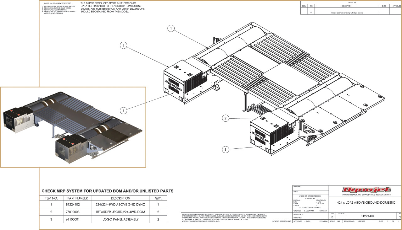
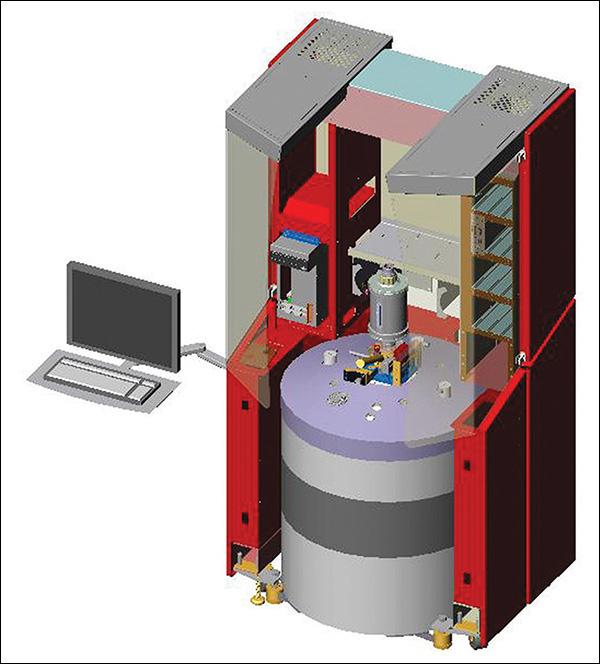
Upper Level Assembly Drawing for a Four-Wheel-Drive Dynamometer (Inset shows 3D model.) (Courtesy of Dynojet Research, Inc.)
Working Drawings or Construction Drawings
The term working drawings describes a set of assembly drawings and detail drawings. A set of civil drawings with site, grading plans, and the many structural details for building a dam or bridge is an example of a set of working drawings.
Architectural drawings are another type of working (or construction) drawings (Figure 14.1). They are given to the contractor to show how to construct the building envisioned by the architect. Working drawings for machines include assembly drawings showing how parts fit together and detail drawings showing how to manufacture the parts. Weldments are a type of assembly drawing showing the welds that must be used to form an assembly from separate pieces of metal.

14.1 Portion of a Mechanical System for a Building (Courtesy of Associated Construction Engineering, Inc.)
Drawings, models, and supporting documentation are the specifications for design manufacture. They are given to contractors to perform the work or manufacture individual parts, so they must represent the design accurately. The drawing is a legal document describing what work is to be performed or what parts are to be produced.
A careful process of checking and approving drawings and models helps prevent errors. Take preparing or approving drawings as a serious responsibility. Overlooking what may seem to be small or insignificant details may result in large amounts of wasted money or, worse, a person’s injury or death.
Assembly Drawings
An assembly drawing shows the assembled machine or structure, with all detail parts in their functional positions or as an exploded view where you can relate the parts to their functional positions.
There are different types of assembly drawings:
1. Design assemblies, or layouts.
2. General assemblies.
3. Detail assemblies.
4. Working drawing assemblies.
5. Outline or installation assemblies.
6. Inseparable assemblies (as in weldments, and others).
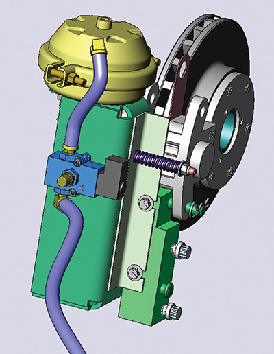
Assembly drawings are often generated from 3D CAD models. For example, the assembly drawing for the air brake in Figure 14.2 was generated from the 3D CAD model of the air brake shown in a shaded view in Figure 14.3.

14.2 General Assembly Drawing for an Air Brake Created from a 3D CAD Model (Courtesy of Dynojet Research, Inc.)
Views
Keep the purpose in mind when you select the views for an assembly drawing. The assembly drawing shows how the parts fit together and suggests the function of the entire unit. A complete set of orthographic views is not required. Often a single orthographic view will show all of the information needed when assembling the parts. The assembly drawing does not need to show how to make the parts, just how to put them together. The assembly worker receives the actual finished parts. The information for each individual part is shown on its detail drawing.
Hidden Lines in Assembly Drawings
Typically, hidden lines are not needed on assembly drawings. Keep in mind that the assembly drawing is often used by the worker who is putting the parts together. It needs to be easy to read and show the relationships between parts clearly. Hidden lines can make the drawing difficult to read, so use section or exploded views to show the interior parts in the assembly drawing.
Dimensions in Assembly Drawings
Assembly drawings are not usually dimensioned except to show the relative positions of one feature to the next when that distance must be maintained at the time of the assembly, such as the maximum height of a jack, or the maximum opening between the jaws of a vise. When machining is required in the assembly operation, the necessary dimensions and notes may be given on the assembly drawing.
Assembly Sections
Because assemblies often have parts fitting into or overlapping other parts, 2D and 3D sections are useful views. For example, in Figure 14.4, try to imagine the right-side view drawn in elevation with interior parts represented by hidden lines.

Any kind of section may be used as needed. A broken-out section is shown in Figure 14.4. Half sections and removed sections are also frequently used. Pictorial sections are helpful in creating easy-to-read assembly drawings.
Detail Drawings or Piece Part Drawings
Drawings of the individual parts are called piece part drawings, part drawings, or detail drawings. Detail drawings contain all of the necessary information to manufacture any specific part being created for a product or design. Figures 14.5 and 14.6 show detail drawings. The information provided on detail drawings includes:
• All necessary drawing views or accurate 3D model information to fully define the shape.
• Dimensions that can be specified in a drawing or can be measured accurately from a 3D model.
• Tolerances either specified in a drawing or annotated in a 3D model so that how the tolerance applies can be clearly understood.
• The material for the manufactured part.
• Any general or specific notes including heat treatment, painting, coatings, hardness, pattern number, estimated weight, and surface finishes, such as maximum surface roughness.
• Approval or release and revision tracking, whether part of a 2D drawing title and revision block or part of a digital signature system.
14.1 Subassemblies
A set of working drawings includes detail drawings of individual parts and the assembly drawing showing the assembled unit. Often, an entire subassembly may be reused in a different design. It is easier to reuse the group of parts in a new design if they are grouped together logically and contained in separate drawings. Your top-level assembly drawing will appear cleaner if you keep subassemblies well organized, as the entire subassembly can be identified as a single item on a higher-level assembly drawing. Fasteners for the subassembly that attach it to its mating parts in the next higher level assembly drawing are usually shown or listed on the bill of materials (sometimes referred to as BOM) at the higher level.
Structuring a product into assemblies and subassemblies requires thoughtful decision making to facilitate retrieving part, subassembly, and assembly drawings later on. If your company uses a product data management system (PDM), planning is essential to seeing downstream results.
An example of a subassembly is shown in Figure 14.7. A subassembly is drawn the same way as an assembly drawing, just for a subgroup that assembles to other parts.
14.2 Identification
Circled numbers called balloon numbers or ball tags are used to identify the parts in the assembly (Figure 14.8). Circles containing the part numbers are placed adjacent to the parts, with leaders terminated by arrowheads touching the parts as shown in Figure 14.9.
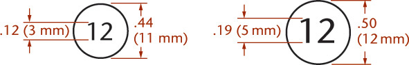
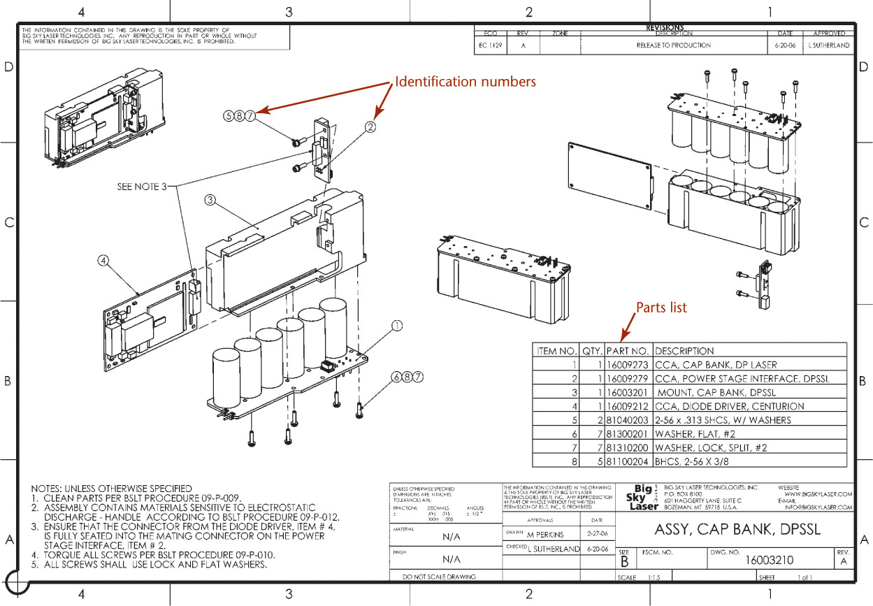
Place the circles in orderly horizontal or vertical rows and not scattered over the sheet. Draw leader lines at an angle, not horizontally or vertically. Do not let leaders cross. Make adjacent leaders parallel or nearly so. For multiple small parts that are easily distinguished, a single leader may have multiple circle item numbers as shown in Figure 14.9.
The circled item number identifies each part. Show information for the part in the parts list. The parts list is usually included on the drawing sheet but may also be a separate document.
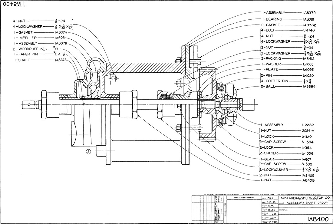
Another method of identification is to letter the part names, numbers required, and part numbers at the end of leaders, as shown in Figure 14.7. More commonly, only the part numbers are given, together with standard straight-line leaders.
Multidetail Drawings
When multiple detail drawings are shown on one sheet, label each part with identification similar to that used on any detail drawings. A portion of a multidetail drawing is shown in Figure 14.10.

14.3 Parts Lists
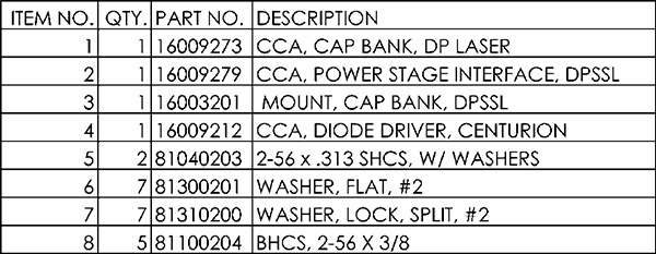
A parts list or bill of materials (BOM) itemizes the parts of a structure shown on an assembly drawing (ANSI Y14.34M). The title strip alone is sufficient on detail drawings of only one part, but a parts list is necessary on assembly drawings or detail drawings of several parts. Parts can be listed in general order of size or importance or grouped by types.
Parts lists for machine drawings (Figure 14.11) contain:
• Part identification number (PIN).
• Description of each part.
• Quantity required in the assembly.
The following abbreviations can be used to indicate quantities that are not exactly known: AR indicating as required; EST followed by a number for an estimated quantity.
Parts lists that contain application data must include information for the next assembly level.
Frequently, other information is supplied in the parts list, such as material, DAI code, pattern numbers, stock sizes, and weights of parts.
Automatic BOM Generation
CAD software often allows you to generate the parts list automatically or somewhat automatically. Some CAD software uses the terminology Parts List, others BOM, and some use both terms but have different command features based on which is selected (they will be considered interchangeable here). Figure 14.12 shows a dialog box used to automate generation of a parts list.
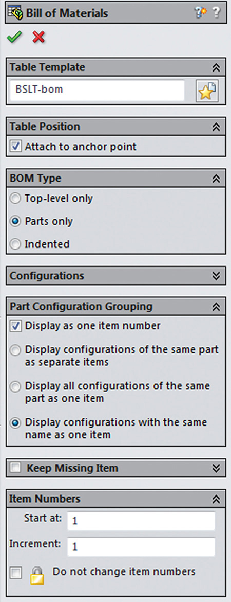
14.12 SolidWorks Dialog Box Showing Options for Automatically Inserting a Bill of Materials Table (Image courtesy of ©2016 Dassault Systèmes SolidWorks Corporation.)
If you created a 3D assembly model by inserting CAD models for the parts, the software can query the assembly model for quantities and the file names that were inserted to generate the parts list. This is another good reason to use good file management practices and name your parts logically. Most software allows you to type in information, but overriding the information this way makes it harder to automatically update files, losing some of the advantage of using 3D CAD.
Locating the Parts List
If the parts list rests on top of the title box or strip, the order of the items should be from the bottom upward so that new items can be added later, if necessary. If the parts list is placed in the upper-right corner, the items should read downward.
Listing Standard Parts
Standard parts, whether purchased or company produced, are not drawn but are included in the parts list. Bolts, screws, bearings, pins, keys, and so on are identified by the part number from the assembly drawing and are specified by name and size or number.
14.4 Assembly Sections
In assembly sections it is necessary not only to show the cut surfaces but also to distinguish between adjacent parts. Do this by drawing the section lines in opposing directions, as shown in Figure 14.13. The first large area is sectioned at 45° (Figure 14.13a). The next large area is sectioned at 45° in the opposite direction. Additional areas are then sectioned at other angles, such as 30° or 60°, as shown ain Figure 14.13c, or at other angles.
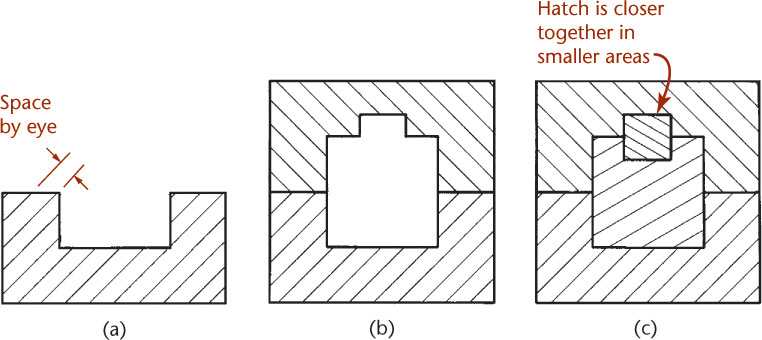
In small areas it is necessary to space the section lines closer together. In larger areas space section lining more widely or use outline section lining.
Use the general-purpose section lining for assemblies. You can also give a general indication of the materials used by using symbolic section lining (Figure 14.14). Refer to Chapter 8 to review section drawing practices.
In sectioning relatively thin parts in an assembly, such as gaskets and sheet metal parts, section lining is ineffective and should be left out or shown in solid black, as in Figure 14.15.

In architectural drawings, filling sectioned areas solidly is called poche, as shown in Figure 14.16. It is often used to show walls that have been cut through, as on floor plans.
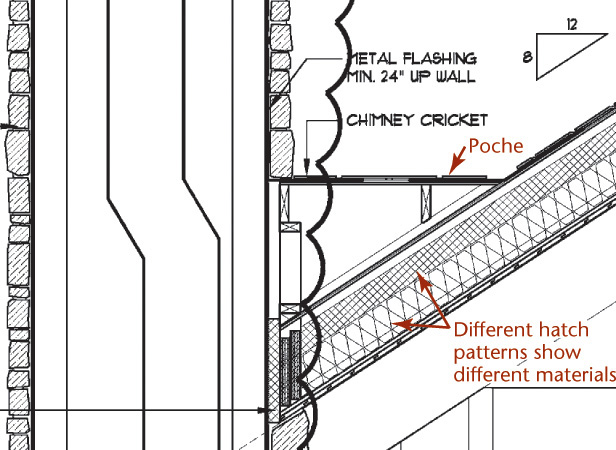
14.16 Architectural Drawing Detail. Use hatch patterns to indicate material and poche small features. (Courtesy of Locati Architects.)
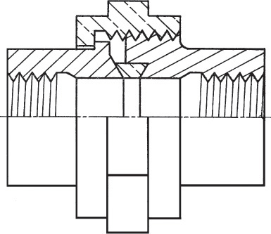
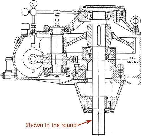
Often solid objects, or parts that do not show required information, are sliced by the cutting plane. Leave these parts unsectioned, or “in the round.” This includes bolts, nuts, shafts, keys, screws, pins, ball or roller bearings, gear teeth, spokes, and ribs, among others. See Figure 14.17.

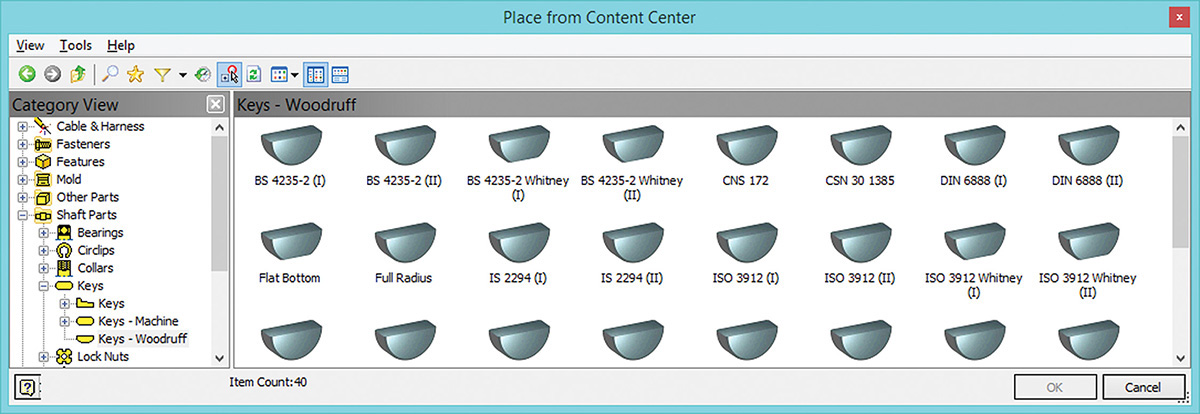
You can save time in creating assemblies by downloading models of stock parts from vendors online. (Autodesk screen shots reprinted courtesy of Autodesk, Inc.)
14.5 Working Drawing Assembly
A working drawing assembly is a combined detail and assembly drawing (Figure 14.18). These drawings are often used in place of separate detail and assembly drawings when the assembly is simple enough for all of its parts to be shown clearly in the single drawing. In some cases, all but one or two parts can be drawn and dimensioned clearly in the assembly drawing, in which event these parts are detailed separately on the same sheet. This type of drawing is common in valve drawings, locomotive subassemblies, aircraft subassemblies, and drawings of jigs and fixtures.
Autodesk Inventor is an example of a software package that features stock parts useful for creating assemblies. (Autodesk screen shots reprinted courtesy of Autodesk, Inc.)
14.6 Installation Assemblies
An assembly made specifically to show how to install or erect a machine or structure is an installation assembly. This type of drawing is also often called an outline assembly, because it shows only the outlines and the relationships of exterior surfaces. A typical installation assembly is shown in Figure 14.19. In aircraft drafting, an installation drawing (assembly) gives complete information for placing details or subassemblies in their final positions in the airplane.
14.7 Check Assemblies
After all detail drawings of a unit have been made, it may be necessary to make a check assembly, especially if a number of changes were made in the details. Such an assembly is shown accurately to scale to graphically check the correctness of the details and their relationship in assembly. After the check assembly has served its purpose, it may be converted into a general assembly drawing.
14.8 Working Drawing Formats
Number of Details Per Sheet
There are two general methods for grouping detailed parts on sheets. Showing one detailed part per sheet is typically preferred because it is easier to repurpose drawings for other uses and to track revision data when the sheet does not contain extra parts.
Small machines or structures composed of few parts sometimes show all the details on one large sheet. Showing the assembly and all its details on one sheet can be convenient, but it is generally more difficult to revise and maintain. The same scale should be used for all details on a single sheet, if possible. When this is not possible, clearly note the scale under each dissimilar detail.
Most companies show one detail per sheet, however simple or small it may be. For many parts the basic 8.5″ × 11″ or 210 mm × 297 mm sheet works well. Because it is easy to lose a few drawings on smaller sheets from a set that is mostly on larger sheets, some companies use 11″ × 17″ (or the equivalent metric size) sheets for all parts.
Digital Drawing Transmittal
Electronic file formats such as Portable Document Format (PDF), originally developed by Adobe Systems in 1993, allow the originator to send a document that can be commented on without allowing the original document to be changed.
Several search engines allow you to search for text embedded in the PDF file. This means that PDF can provide advantages not just for storing, but retrieving the information later. Adobe Systems provides a useful document (in PDF format) on using PDF as an archiving standard. Dassault Systèmes’ eDrawings Viewer is a popular format for viewing, printing, and marking up drawings produced in SolidWorks and AutoCAD. It runs on Windows, Mac OS, and mobile platforms and does not require the user to have any CAD software installed.
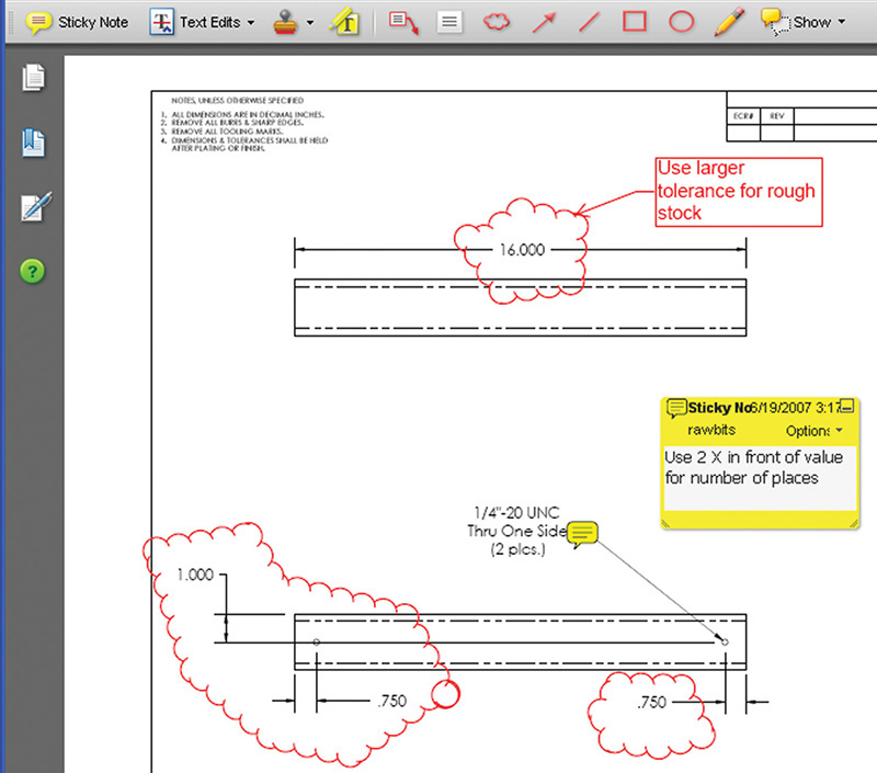
Using electronic files saves trees, makes it quicker to distribute and store documents, and allows others to review documents from various applications. Figure 14.20 shows a drawing stored in PDF format with comments and redlined markups.
Paper Conservation

(Copyright Mykola Mazuryk/Shutterstock.)
According to Worldwatch Institute, 40% of the trees harvested worldwide are used to make paper. The U.S. Environmental Protection Agency (EPA) estimates that paper makes up 38% of municipal solid waste.
Total global consumption of paper is still rising, reaching 371 million tons in 2009. However according to RISI, total paper consumption in North America declined 24% between 2006 and 2009, dropping from more than 652 lbs per person yearly in 2005 to 504 lbs yearly in 2009. In 2009, total paper consumption in China eclipsed total North American consumption for the first time.
Websites related to paper conservation include:
• www.lesk.com/mlesk/ksg97/ksg.xhtml
Title and Record Strips
Drawings constitute important and valuable information regarding products, so carefully designed, well-kept, systematic files are important.
The function of the title and record strip is to show, in an organized way, all necessary information not given directly on the drawing with its dimensions and notes. The type of title used depends on the filing system in use, the manufacturing processes, and the requirements of the product. The following should generally be given in the title form:
1. Name of the object shown.
2. Name and address of manufacturer.
3. Name and address of the purchasing company, if any.
4. Signature of the person who made the drawing and date of completion.
5. Signature of the checker and date of completion.
6. Signature of the chief drafter, chief engineer, or other official, and the date of approval.
7. Scale of the drawing.
8. Number of the drawing.
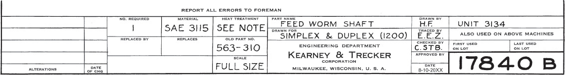
Other information may be included, such as material, quantity, heat treatment, finish, hardness, pattern number, estimated weight, superseding and superseded drawing numbers, symbol of machine, and so on, depending on the plant organization and unique aspects of the product. Some typical title blocks are shown in Figures 14.21, 14.22, and 14.23.


The title form is usually placed along the bottom of the sheet or in the lower right-hand corner of the sheet, because drawings are often filed in flat, horizontal drawers, and the title must be easily found. However, as many filing systems are in use, the location of the title form depends on a company’s organizational preference. Many companies adopt their own title forms or those preferred by ANSI.
To letter items in a title form:
• Use single-stroke vertical or inclined Gothic capitals.
• Letter items according to their relative importance. Use heavier, larger or more widely spaced lettering (or a combination of these) to indicate important items.
• Give the drawing number the most emphasis, followed by the name of the object and name of the company. (Date, scale, and originator’s and checker’s names are important, but do not need to be prominent.)
• Refer to Chapter 2 for detailed information on title blocks and standard letter heights.
14.9 Drawing Numbers
Every drawing should be numbered. Some companies use serial numbers, such as 60412, or a number with a prefix or suffix letter to indicate the sheet size, as A60412 or 60412-A. The size A sheet is a standard 8.5″ × 11″.
In different numbering schemes, various parts of the drawing number indicate different things, such as model number of the machine and the nature or use of the part. In general, it is best to use a simple numbering system and not to load the number with too many indications.
The drawing number should be lettered 7 mm (.2500″) high in the lower-right and upper-left corners of the sheet.
To benefit from a CAD system, you must be able to store and retrieve your drawings efficiently. Drawing tracking software allows users to search by part number or by text items to locate and retrieve drawing files and CAD models.
14.10 Zoning
To help people locate a particular item on a large or complex drawing, regular ruled intervals are labeled along the margins, often in the right and lower margins only. The intervals on the horizontal margin are labeled from right to left with numerals, and the intervals on the vertical margin are labeled from bottom to top with letters, similar to road maps. Note the zone letters and numbers around the border of Figure 14.24.
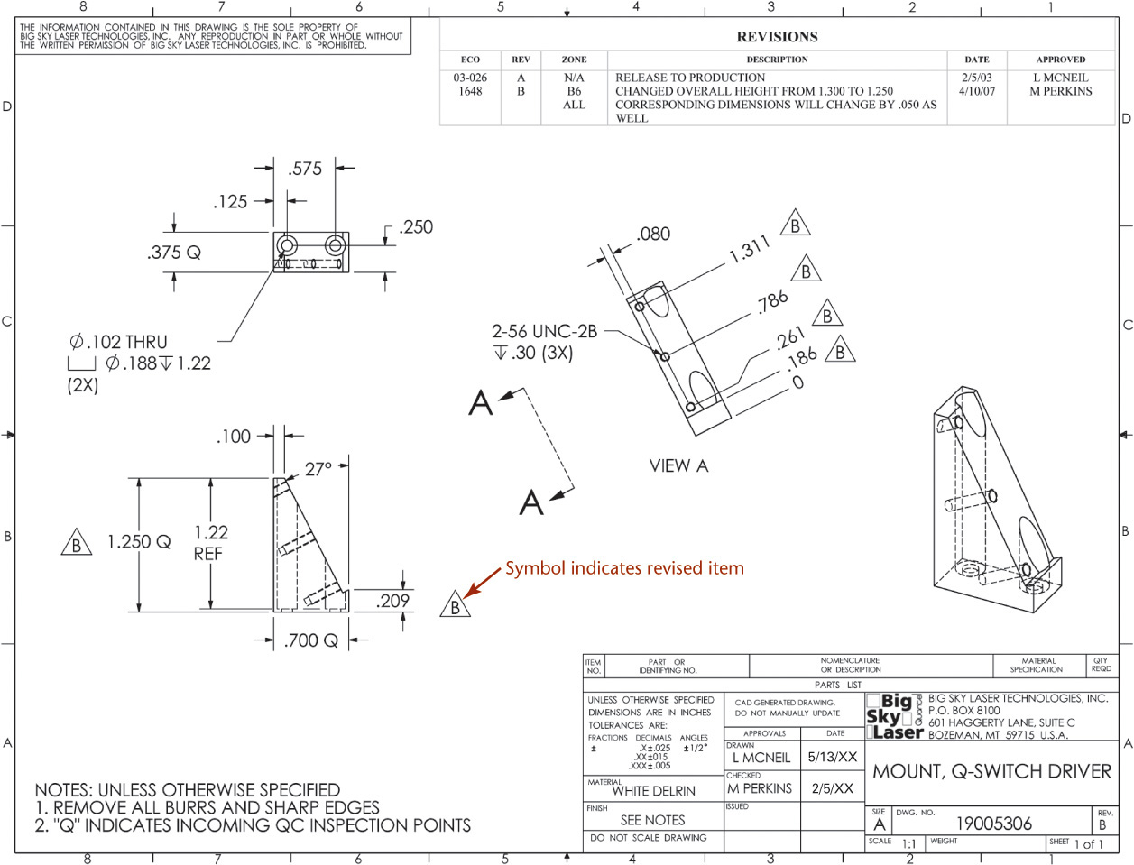
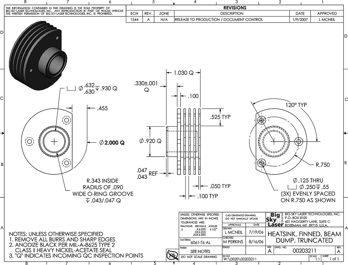
14.24 Symbols match the item in the revision block to revised features on a drawing. (Courtesy of Big Sky Laser, Inc.)
14.11 Checking Drawings
The importance of accuracy in technical drawing cannot be overstated. Errors sometimes cause tremendous unnecessary expenditures. The signature on the drawing identifies who is responsible for its accuracy.
In small offices, checking is usually done by the designer or by one of the drafters. In large offices, experienced engineers may be employed to devote a major part of their time to checking drawings.
A drawing is carefully checked and signed by the person who made it. It is then checked by the lead designer for function, economy, practicability, fit, tolerances, and so on. Corrections, if any, are then made by the original drafter.
The final checker should systematically review the drawing for any remaining errors. They should study the drawing with particular attention to:
1. Soundness of design, with reference to function, strength, materials, economy, manufacturability, serviceability, ease of assembly and repair, lubrication, and so on.
2. Choice of views, partial views, auxiliary views, sections, lettering, and so on.
3. Dimensions, with special reference to repetition, ambiguity, legibility, omissions, errors, and finish marks. Special attention should be given to tolerances.
4. Standard parts. In the interest of economy, as many parts as possible should be standard.
5. Notes, with special reference to clear wording and legibility.
6. Clearances. Moving parts should be checked in all possible positions to ensure freedom of movement.
7. Title form information.
14.12 Drawing Revisions
Changes on drawings may be necessitated by changes in design, changes in tools, customer desires, or errors in design or in production. An accurate record of all changes made to released drawings is tracked via a revision block. This is important so that the sources of all changes may be understood, verified, and approved.
The record of revisions should show the change, by whom, when, and why the change was made. An engineering change order (ECO) or engineering change request (ECR) is processed to approve and track changes to drawings once they have been released for production. Some companies use a paper record for this and others manage it digitally.
Any changes or additions made to a drawing are tracked by a revision number. A symbol can be added to the drawing showing the item affected by the revision.
It is not recommended to remove information by crossing it out.
In rare cases when a dimension is not noticeably affected by a change, it may be underlined with a heavy line to indicate that it is not to scale.
It is important to keep prints or microfilms of each issue on file to show how the drawing appeared before the revision. Issue new prints to supersede old ones each time a change is made.
Digital systems absolutely must use careful backup procedures and, due to data loss concerns, are still not approved in some industries.
If considerable change on a drawing is necessary, it may be necessary to make a new drawing and stamp the old one OBSOLETE and store it in an “obsolete” file. In the title block of the old drawing, enter the words “SUPERSEDED BY” or “REPLACED BY” followed by the number of the new drawing. On the new drawing, under “SUPERSEDES” or “REPLACES,” enter the number of the old drawing.
People use various methods to link the area on a drawing where the change is made to the entry in the revision block. The most common is to place numbers or letters in a small circle or triangle near each place where the changes were made and to use the same numbers or letters in the revision block, as shown in Figure 14.24. On zoned drawings, the zone of the correction is shown in the revision block. The change should also be described briefly, along with the date and initials of the person making the change.
14.13 Simplifying Drawings
Drawing time is a considerable part of the total cost of a product. It makes sense to reduce drawing costs by using practices to simplify your drawings without losing clarity. For example, use partial views, half views, thread symbols, piping symbols, and single-line spring drawings when appropriate. Omit lines or lettering on a drawing that are not needed for clarity. In addition to saving production time, this makes drawings easier to read. To simplify drawings:
1. Use word descriptions when practical.
2. Do not show unnecessary views.
3. Use standard symbols such as ∅ and standard abbreviations (see Appendix 2) when appropriate.
4. Avoid elaborate, pictorial, or repetitive details. Use phantom lines to avoid drawing repeated features.
5. List rather than draw standard parts such as bolts, nuts, keys, and pins.
6. Omit unnecessary hidden lines.
7. Use outline section lining in large areas to save time and improve legibility.
8. Omit unnecessary duplication of notes and lettering.
9. Use symbolic representation for piping and thread.
10. Use CAD libraries and standard parts when feasible for design and drawings.
Some industries have simplified their drafting practices even more. Learn the practices appropriate to the industry for which you are creating drawings.
14.14 Patent Drawings
The patent application for a machine or device must include drawings to illustrate and explain the invention. All patent drawings must be mechanically correct and constitute complete illustrations of every feature of the invention claimed. The strict requirements of the U.S. Patent Office facilitate the examination of applications and the interpretation of patents issued. Examples of patent drawings are shown in Figure 14.25.
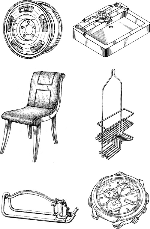
14.25 Patent Drawing Examples. Although several examples are shown here, each drawing is shown on a separate sheet in the patent application. (Courtesy of US. Patent and Trademark Office.)
Drawings for patent applications are pictorial and explanatory in nature; therefore they are not as detailed as working drawings for production purposes. Centerlines, hidden lines, dimension notes, and so forth, are omitted, since specific dimensions, tolerances, and notes are often not required to patent the general design or innovation.
The drawings must contain as many figures as necessary to show the invention clearly. There is no limit on the number of sheets that may be submitted. The drawings can be produced by hand or from the same CAD database used to create the design documentation.
While most engineering drawings are produced with views in alignment on one sheet, patent drawings must show each separate view as one figure on a separate sheet. Figures should be numbered consecutively (e.g., Figure 1, Figure 2, Figure 3A, Figure 3B, etc.). Views, features, and parts are identified by numbers that refer to the descriptions and explanations given in the specification section of the patent application. The reference number for a part or feature should remain the same in every diagram.
Exploded isometric or perspective drawings with reference numbers identifying the parts (i.e., assembly drawings) are preferred. Centerlines are used to illustrate how parts are aligned in exploded views. While the drawing must show every feature that is listed in the patent claims, if standardized parts are used, they can be represented symbolically and do not have to be drawn in detail.
The figures may be plan, elevation, section, pictorial, and detail views of portions or elements, and they may be drawn to an enlarged scale if necessary.
The U.S. Patent Office has basic standards for drawings:
• All sheets within a single application must be the same size, and two sheet sizes are accepted:
• U.S. size: 8.5″ by 11″ (216 mm × 279 mm).
• International size: 210 mm × 297 mm.
• Paper must be single sided.
• Paper must be oriented vertically, so that the short side of the sheet is at the top (called portrait style in printing options).
• No border lines are permitted on the sheets.
• The following minimum margins must be maintained.
• Top margin: 1″ (25 mm).
• Left margin: 1″ (25 mm).
• Right margin: .675″ (15 mm).
• Bottom margin: .375″ (10 mm).
• No labels or drawing lines may extend into the margin except for the specific identification required at the top of each sheet and two scan target points.
• All drawings must be submitted in black and white—no color drawings or photos except in very limited cases.
• Lines must be solid black and suitable for reproduction at a smaller size.
• Shading (either cross hatch or stippling) is used whenever it improves readability. In rare cases when it is necessary to show a feature hidden behind a surface, a lighter solid line is used.
• Sketches are acceptable for the application process, but formal drawings will have to be created if accepted.
Photocopies are accepted, because three copies of each drawing must be submitted. The drawings will not be returned so it is not a good idea to send an original with the initial patent application.
While the above gives you a basic idea of the standards for patent drawings, the strict requirements of the U.S. Patent Office are carefully documented on their website. Be sure to follow their requirements exactly if you are preparing drawings for a patent application.
For more information, log on to the U.S. Patent and Trademark Office’s Web site at www.uspto.gov.
You can also consult the Guide for Patent Draftsmen, which can be obtained from the Superintendent of Documents, U.S. Government Printing Office, Washington, D.C. 20402.
CAD at Work: Assembly Drawings Using 3D CAD
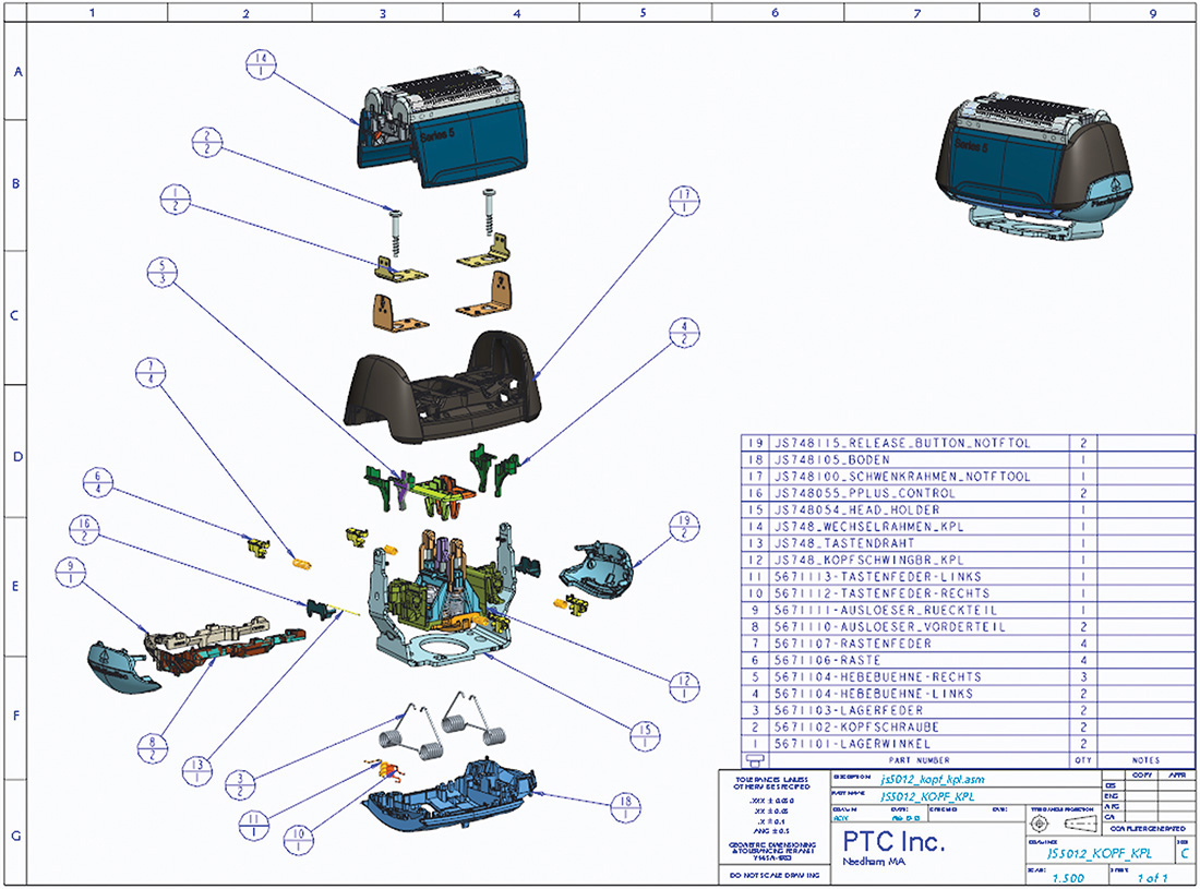
Example of a Color shaded Exploded View Assembly from PTC® Creo® (Copyright © PTC Inc.)
Great looking assembly drawings are only one of the benefits of using 3D CAD for your designs. You can also check to see how parts fit together, perform tolerance studies, and even see how mechanisms you are designing will behave. Additionally, you can analyze the mass properties of your design, determine the volume and surface area of complicated shapes, and produce documentation drawings directly from the part models.
Software like PTC® Creo® allows you to use color shaded views of models in the exploded view assembly drawing, as shown in the figure above.
As you decide whether to use a color shaded drawing or a black and white line drawing for an assembly drawing, consider whether and how the drawing will be reproduced. Shaded color views make it easy to identify and visualize the parts, but require color printing and copying to look their best on paper. This does not present a problem if you are distributing files electronically.
Even though color shaded drawings look great, there are times when black and white drawings are preferable, or required. For example, patent drawings must be black and white, showing visible lines and not hidden lines. Black and white drawings are also helpful in user manuals, which may be copied or printed in black and white.
With 3D CAD software, it is not difficult to switch between color shaded views, outlines, and views that show hidden lines to suit the particular need that the drawing will meet.
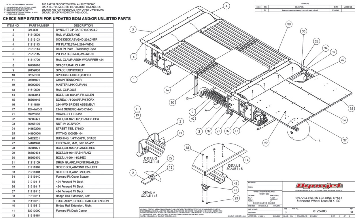
Assembly Drawing for Four Wheel Drive Pit Dyno (Courtesy of Dynojet Research, Inc.)
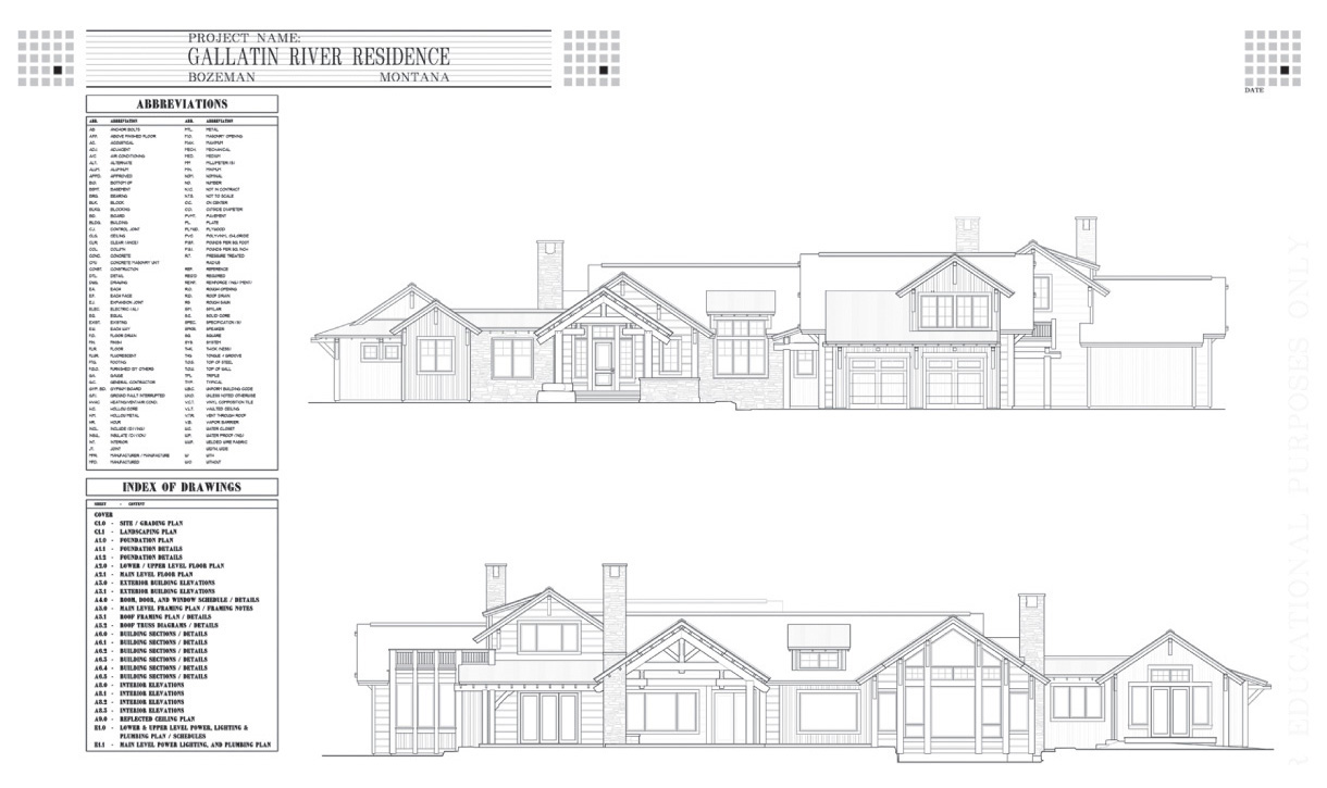
Cover Sheet for Architectural Plans Lists Drawings in the Set and Abbreviations Used. (Courtesy of Locati Architects.)
Assembly Layout
Chapter Summary
• The final drawings created during the design process include assembly drawings, working drawings, design drawings, and patent drawings.
• There are many revisions to drawings during the design process. The drafter must keep track of each version and what changes were made.
• Managing complex projects often involves considering how parts are grouped into subassemblies. Subassembly drawings are similar to assembly drawings, but show a group of parts rather than the entire project.
• Assembly drawings may use one of several different types of views, such as sections, exterior views, exploded views, pictorial views.
• A parts list or bill of materials tracks the items in the assembly or subassembly. As a minimum, it typically contains the item number, description, quantity, and material for the parts.
Review Questions
1. What kinds of information are included in an assembly drawing?
2. How is a detail drawing different from an assembly drawing?
3. Why are drawings numbered? Why is this numbering so important?
4. Describe the drawing revision process. Why is it so important to keep track of revisions?
5. How are revised paper drawings stored? How are revised CAD drawings stored?
6. How does inserting parts to form subassemblies save time in documenting designs?
7. What are the special requirements of a patent drawing?
Chapter Exercises
Design Exercises
The following suggestions for project assignments are of a general and very broad nature, and it is expected that they will help generate many ideas for specific design projects. Much design work is undertaken to improve an existing product or system by utilization of new materials, new techniques, or new systems or procedures. In addition to the design of the product itself, another large amount of design work is essential for the tooling, production, and handling of the product. You are encouraged to discuss with your instructor any ideas you may have for a project.
Each solution to a design problem, whether prepared by an individual student or formulated by a group, should be in the form of a report, which should be typed or carefully lettered, assembled, and bound. It is suggested that the report contain the following (or variations of the following, as specified by your instructor).
1. A title sheet. The title of the design project should be placed in approximately the center of the sheet, and your name or the names of those in the group in the lower right-hand corner. The symbol PL should follow the name of the project leader.
2. Table of contents with page numbers.
3. Statement of the purpose of the project with appropriate comments.
4. Preliminary design sketches, with comments on advantages and disadvantages of each, leading to the final selection of the best solution. All work should be signed and dated.
5. An accurately made pictorial and/or assembly drawing(s), using traditional drawing methods or CAD as assigned, if more than one part is involved in the design.
6. Detail working drawings, freehand, mechanical, or CAD-produced as assigned. The 8.5″ × 11″ sheet size is preferred for convenient insertion in the report. Larger sizes may be bound in the report with appropriate folding.
7. A bibliography or credit for important sources of information, if applicable.
Exercise 14.1 Design new or improved playground, recreational, or sporting equipment. For example, a new child’s toy could be both recreational and educational. Create an assembly drawing.
Exercise 14.2 Design new or improved health equipment. For example, physically handicapped people need special equipment.
Exercise 14.3 Design a cup holder attachment to retrofit cars. It must accommodate a range of cup sizes from 8 oz to 64 oz.
Exercise 14.4 Design a guitar stand to support either an acoustic or electric guitar. It should be convenient and stable, suitable for use on stage. Allow for quick change of guitars by the musician.
Exercise 14.5 Break up into design teams. See how many different ideas each team can come up with for a new layout of your classroom. Time limit is 20 minutes.
Exercise 14.6 Design a new or improved bike safety lock and chain. Integrate the locking devices into the bike’s frame, if possible. Create an assembly drawing showing the features of your design.
Working Drawing Exercises
The problems in Exercises 14.7–14.62 are presented to give you practice in making the type of regular working drawings used in industry. Many exercises, especially assemblies, offer an opportunity to exercise your ability to redesign or improve on the existing design. Due to the variations in sizes and in scales that may be used, you are required to select the sheet sizes and scales, when these are not specified, subject to the approval of the instructor. Standard sheet layouts are shown inside the front cover of this book. (Any of the title blocks shown inside the back cover of this book may be used, with modification if desired, or you may design the title block if assigned by the instructor.)
The statements for each problem are intentionally brief, and your instructor may vary the requirements. Use the preferred metric system or the acceptable complete decimal-inch system, as assigned.
In problems presented in pictorial form, the dimensions and finish marks are to provide you the information necessary to make the orthographic drawing or solid model. The dimensions given are in most cases those needed to make the parts, but due to the limitations of pictorial drawings they are not in all cases the dimensions that should be shown on the working drawing. In the pictorial problems, the rough and finished surfaces are shown, but finish marks are usually omitted. You should add all necessary finish marks and place all dimensions in the preferred places in the final drawings.
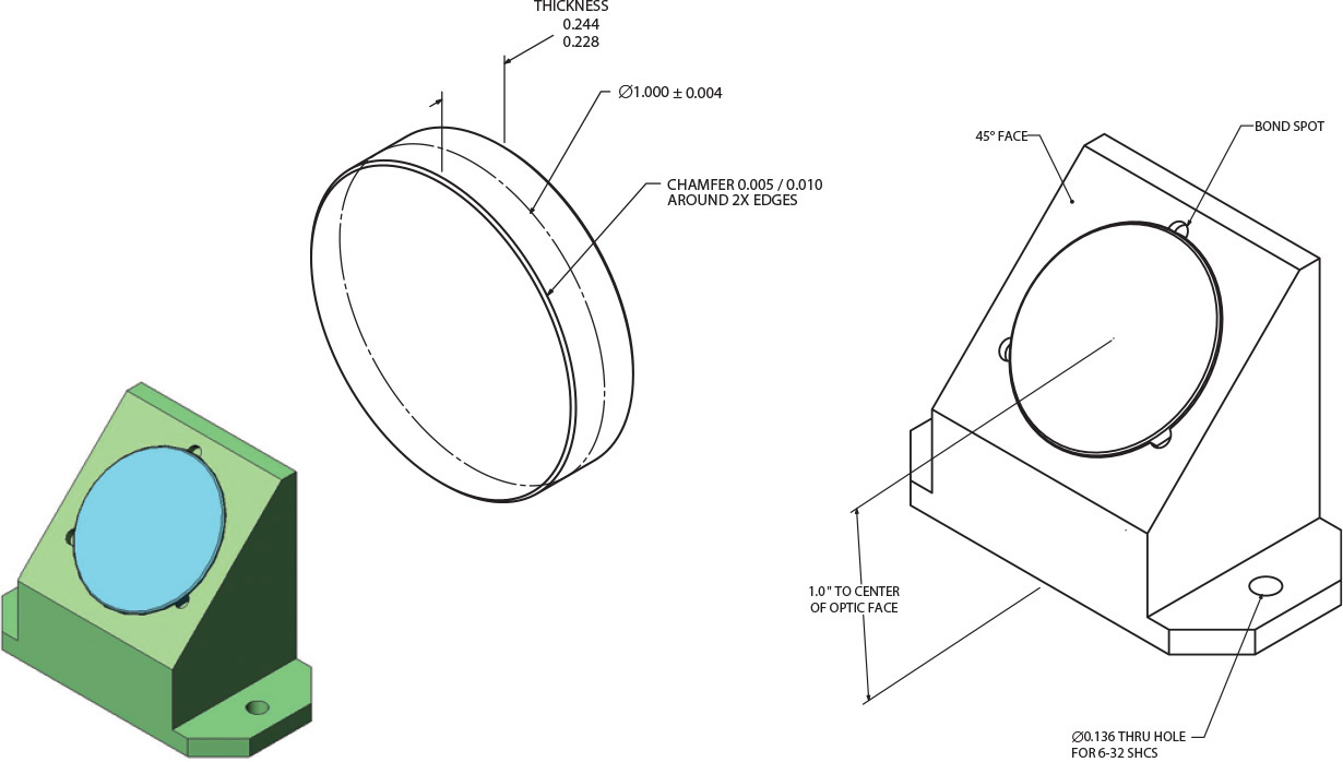
Exercise 14.7 Create part drawings and an assembly for the optical lens and mount. Maintain the critical distances and precise 45° angle for the lens.
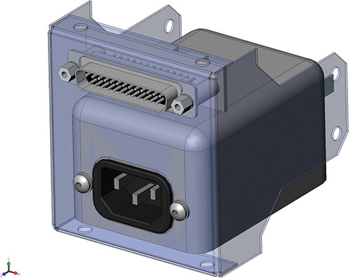
Exercise 14.8 Design the sheet metal housing for the power and D-sub connectors shown. Download stock models for standard parts. Create the flat patterns for the sheet metal if assigned by your instructor.
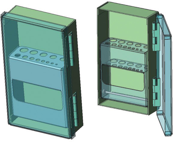
Exercise 14.9 Design a sheet metal drill bit case. Create detailed part and assembly drawings. Develop the flat patterns if assigned. Use “relations” in your model so that you can change the sizes for the holes and overall height, width and depth for the case and automatically update your design to different configurations.
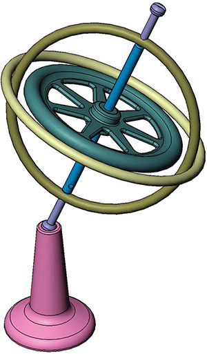
Exercise 14.10 Create an exploded assembly drawing for the gyroscope. Create detail drawings for the parts as assigned by your instructor. Dimensioned parts are shown on the facing page.
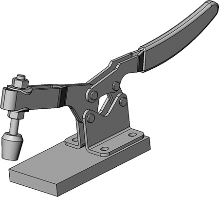
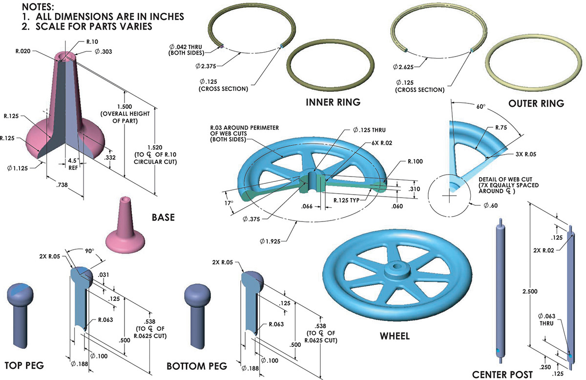
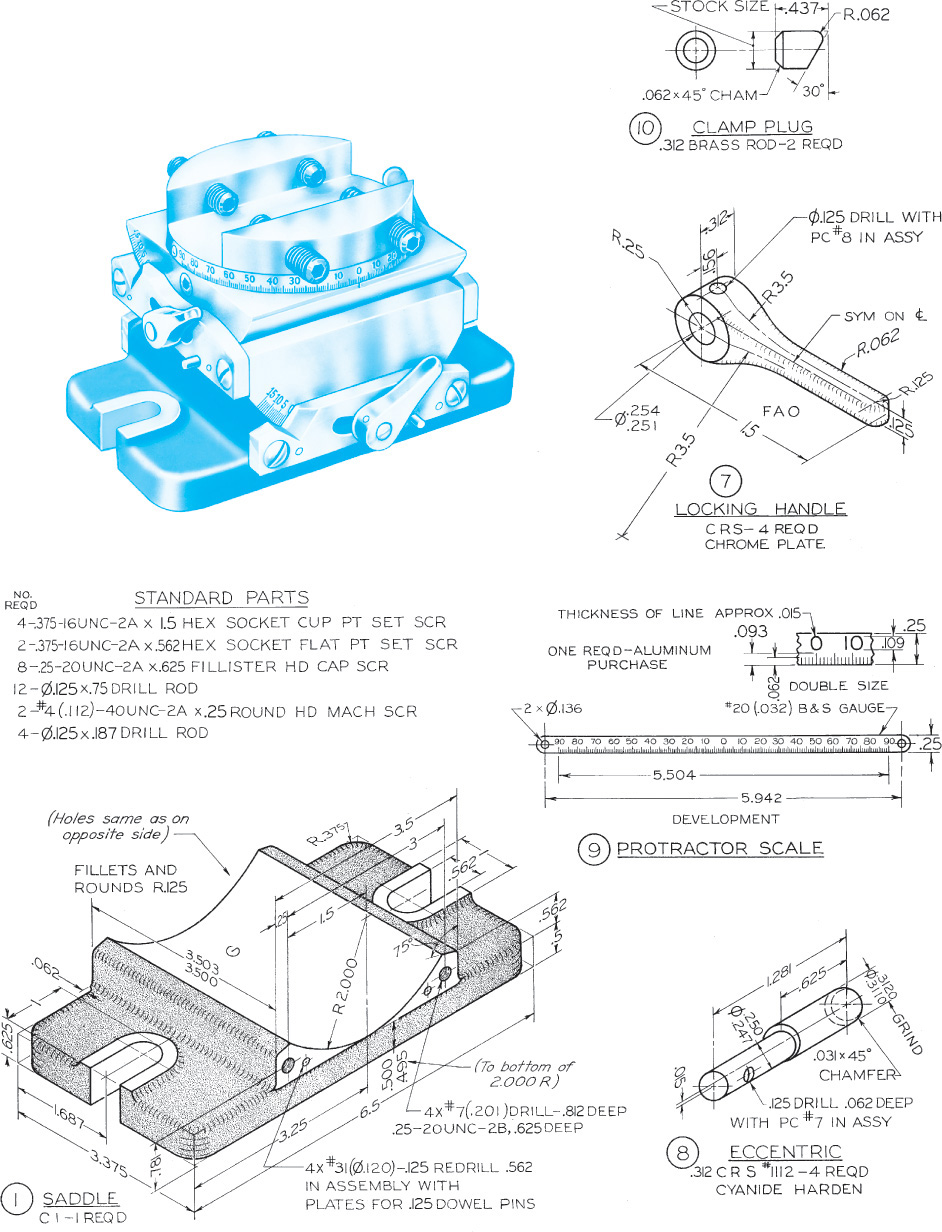
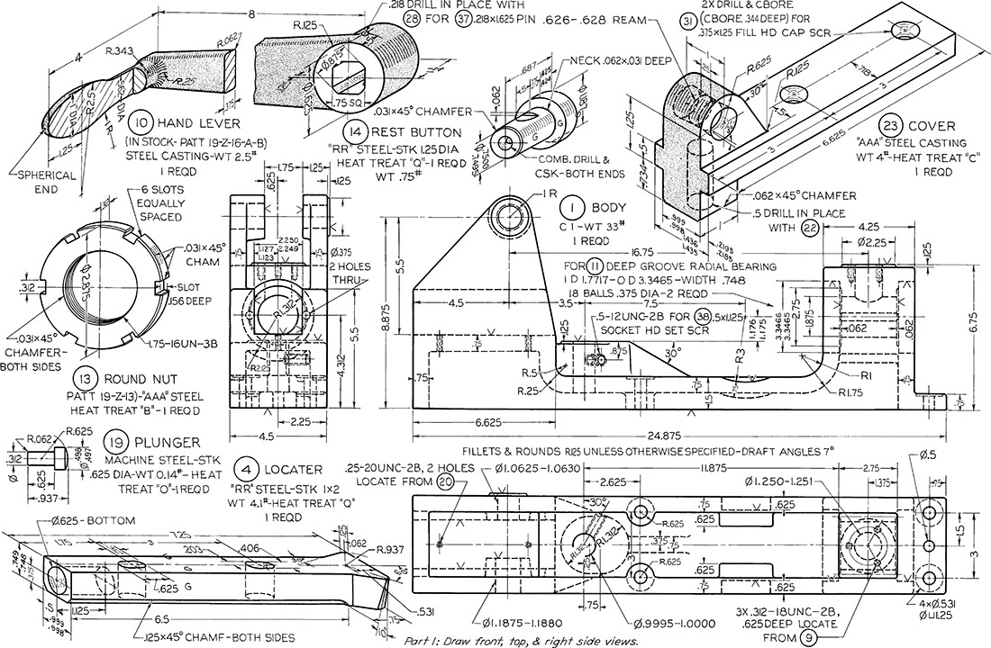
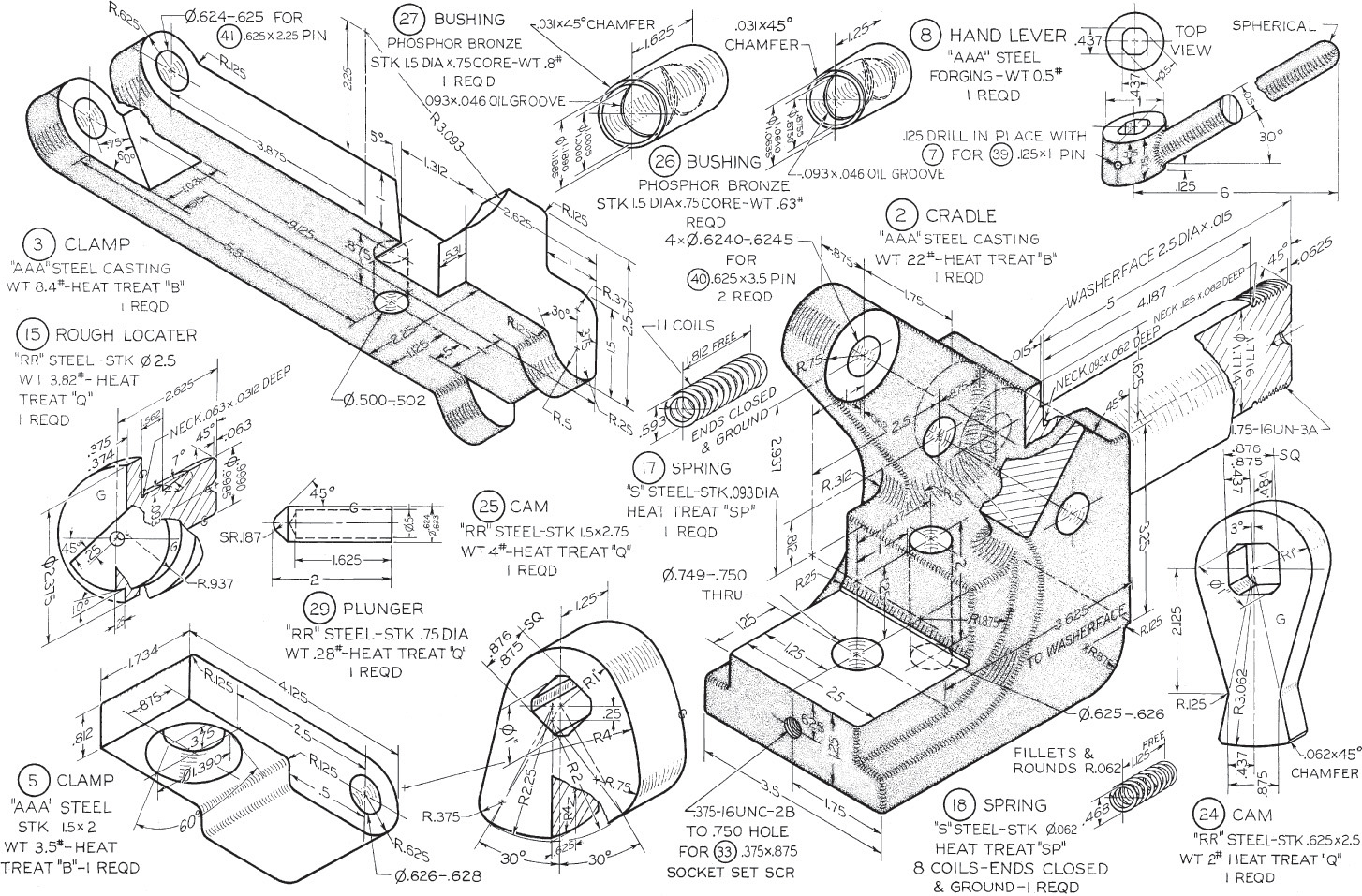
Exercise 14.11 Create an exploded assembly drawing for the clamp. Dimensioned parts are shown on pages 662–663.
Exercise 14.10 Gyroscope, continued
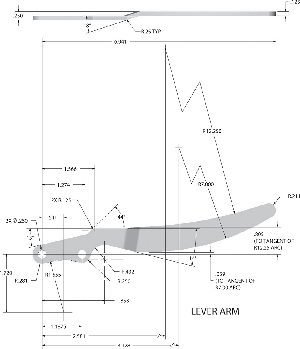
Exercise 14.11 Clamp, continued

Exercise 14.11 Clamp, continued
Exercise 14.12 Make a detail drawing for the table bracket.
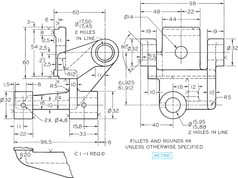
Exercise 14.13 Make a detail drawing for the RH tool post. If assigned, convert dimensions to metric.

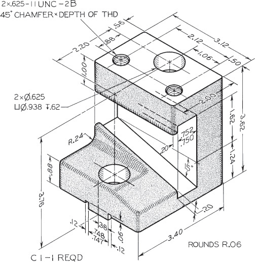
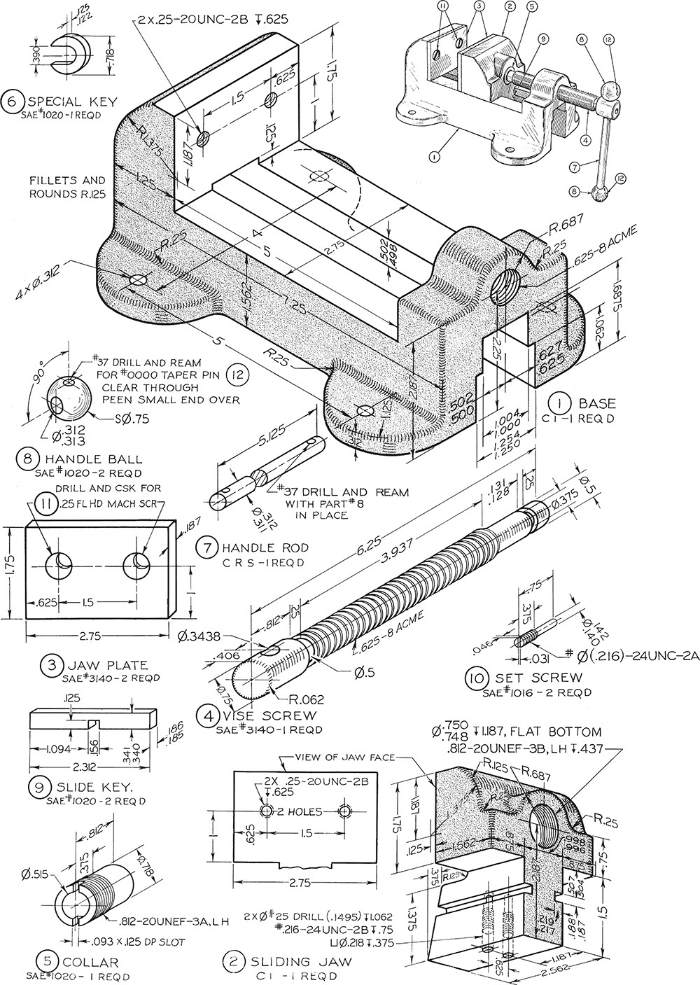
Exercise 14.14 Make a detail drawing for the drill press base. Use unidirectional metric or decimal-inch dimensions.

Exercise 14.15 Make a detail drawing for the shifter fork. If assigned, convert dimensions to metric system.

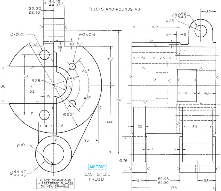
Exercise 14.16 Make a detail drawing for the idler arm.
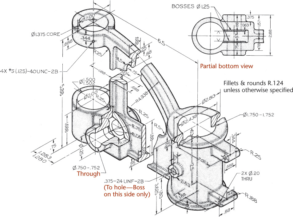
Exercise 14.17 Make a detail drawing for the drill press bracket. If assigned, convert dimensions to decimal inches or redesign the part with metric dimensions.
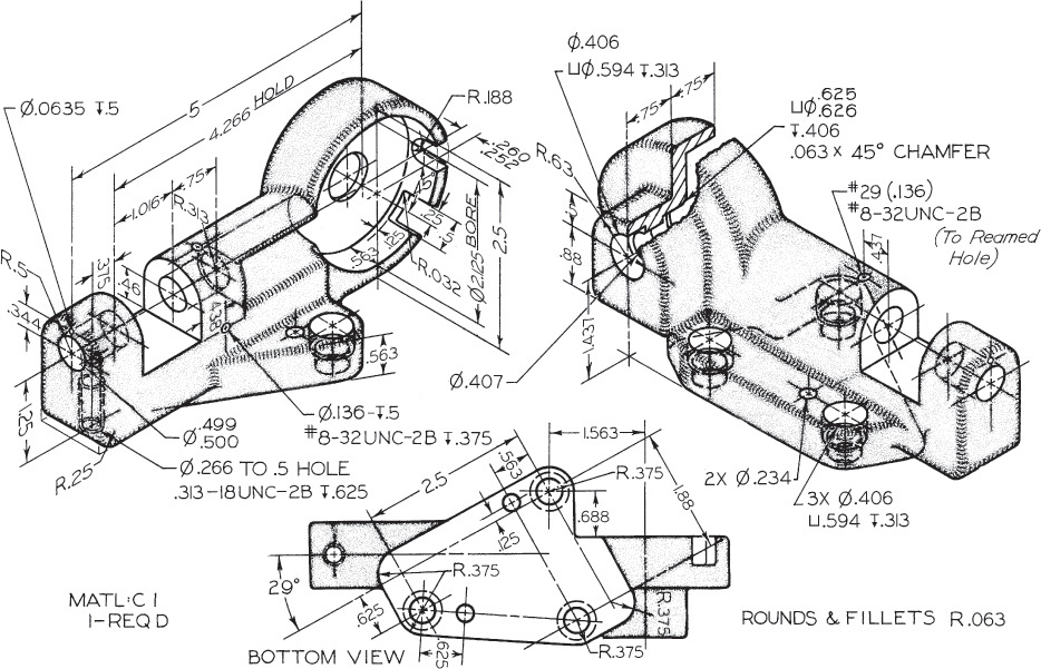
Exercise 14.18 Make a detail drawing for the dial holder. If assigned, convert dimensions to decimal inches or redesign the part with metric dimensions.
Exercise 14.19 Make detail drawings half size for the rack slide. If assigned, convert dimensions to decimal inches or redesign the part with metric dimensions.
Exercise 14.20 Make a detail drawing half size for the automatic stop box. If assigned, redesign the part with metric dimensions.

Exercise 14.21 Make detail drawings half size for the conveyer housing. If assigned, convert dimensions to decimal inches or redesign the parts with metric dimensions.

Exercise 14.22 For the spindle housing, draw as follows. Given: Front, left-side, and bottom views, and partial removed section. Required: Front view in full section, top view, and right-side view in half section on A-A. Draw half size. If assigned, dimension fully.
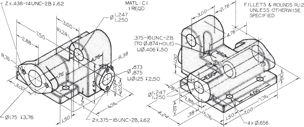
Exercise 14.23 For the arbor support bracket, draw the following. Given: Front and right-side views. Required: Front, left-side, and bottom views, and a detail section A-A. Use American National Standard tables for indicated fits and, if required, convert to metric values (see Appendices 4–13). If assigned, dimension in the metric or decimal-inch system.

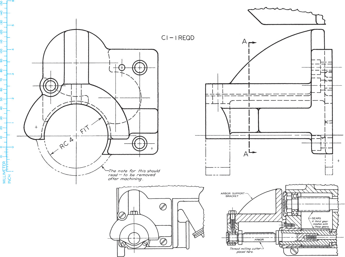
Exercise 14.24 For the pump bracket for a thread milling machine, draw the following. Given: Front and left-side views. Required: Front and right-side views, and top view in section on A-A. Draw full size. If assigned, dimension fully.
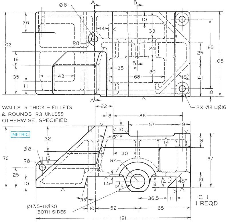
Exercise 14.25 For the support base for planer, draw the following. Given: Front and top views. Required: Front and top views, left-side view in full section A-A, and removed section B-B. Draw full size. If assigned, dimension fully.
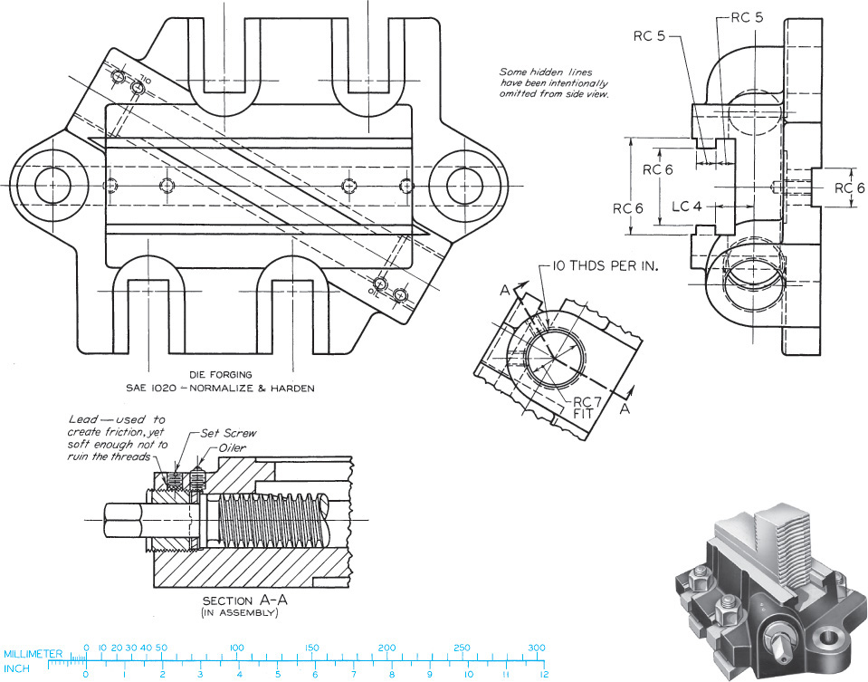
Exercise 14.26 For the jaw base for chuck jaw, draw the following. Given: Top, right-side, and partial auxiliary views. Required: Top, left-side (beside top), front, and partial auxiliary views complete with dimensions, if assigned. Use metric or decimal-inch dimensions. Use American National Standard tables for indicated fits, or convert to metric values (see Appendices 4–13).
Exercise 14.27 For the fixture base for 60-ton vertical press, draw the following. Given: Front and right-side views. Required: Revolve front view 90° clockwise, then add top and left-side views. Draw half size. If assigned, complete with dimensions.
Exercise 14.28 For the bracket, draw the following. Given: Front, left-side, and bottom views, and partial removed section. Required: Make detail drawing. Draw front, top, and right-side views, and removed sections A-A and B-B. Draw half size. Draw section B-B full size. If assigned, complete with dimensions.

Exercise 14.29 For the roller rest bracket for automatic screw machine, draw the following. Given: Front and left-side views. Required: Revolve front view 90° clockwise, then add top and left-side views. Draw half size. If assigned, complete with dimensions.
Exercise 14.30 For the guide bracket for gear shaper, draw the following. Given: Front and right-side views. Required: Front view, a partial right-side view, and two partial auxiliary views taken in direction of arrows. Draw half size. If assigned, complete with unidirectional dimensions.
Exercise 14.31 For the rear tool post, draw the following. Given: Front and left-side views. Required: Take left-side view as new top view; add front and left-side views, approx. 215 mm apart, a primary auxiliary view, then a secondary view taken so as to show true end view of 19 mm slot. Complete all views, except show only necessary hidden lines in auxiliary views. Draw full size. If assigned, complete with dimensions.
Exercise 14.32 For the bearing for a worm gear, draw the following. Given: Front and right-side views. Required: Front, top, and left-side views. Draw full size. If assigned, complete with dimensions.

Exercise 14.33 For the caterpillar tractor piston, draw the following. Make detail drawing full size. If assigned, use unidirectional decimal-inch system, converting all fractions to two place decimal dimensions, or convert all dimensions to metric.

Exercise 14.34 For the generator drive housing, draw the following. Given: Front and left-side views. Required: Front view, right-side view in full section, and top view in full section on A-A. Draw full size. If assigned, complete with dimensions.

Exercise 14.35 For the machinist’s clamp, draw the following. Draw details and assembly. If assigned, use unidirectional two place decimal-inch dimensions or redesign for metric dimensions.
Exercise 14.36 For the hand rail column, draw the following. (1) Draw details. If assigned, complete with dimensions. (2) Draw assembly.

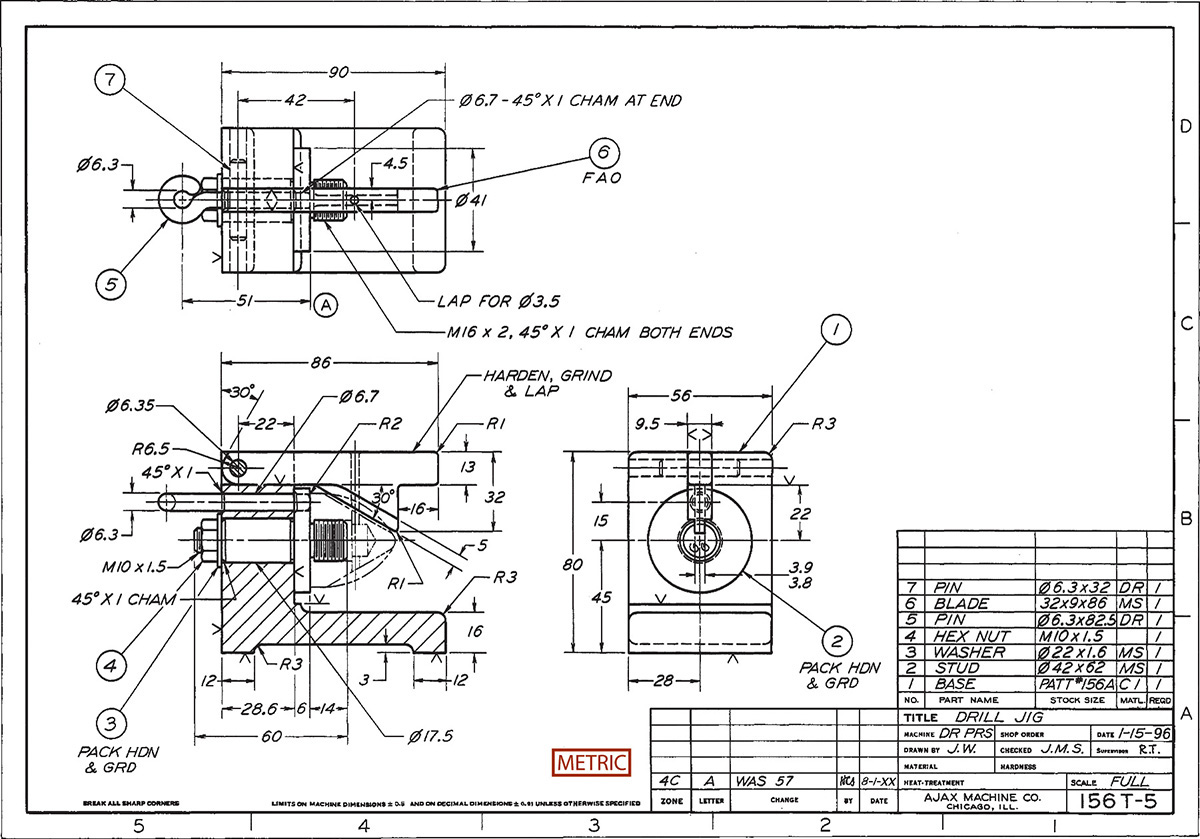
Exercise 14.37 For the drill jig, draw the following. (1) Draw details. If assigned, complete with dimensions. (2) Draw assembly.

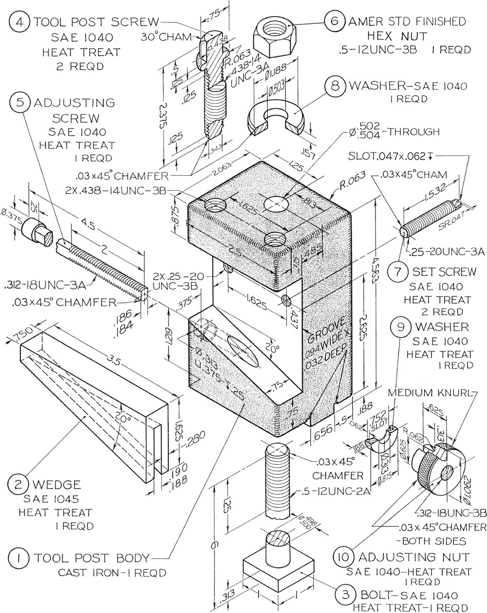
Exercise 14.38 For the tool post, draw the following. (1) Draw details. (2) Draw assembly. If assigned, use unidirectional two place decimals for all fractional dimensions or redesign for all metric dimensions.
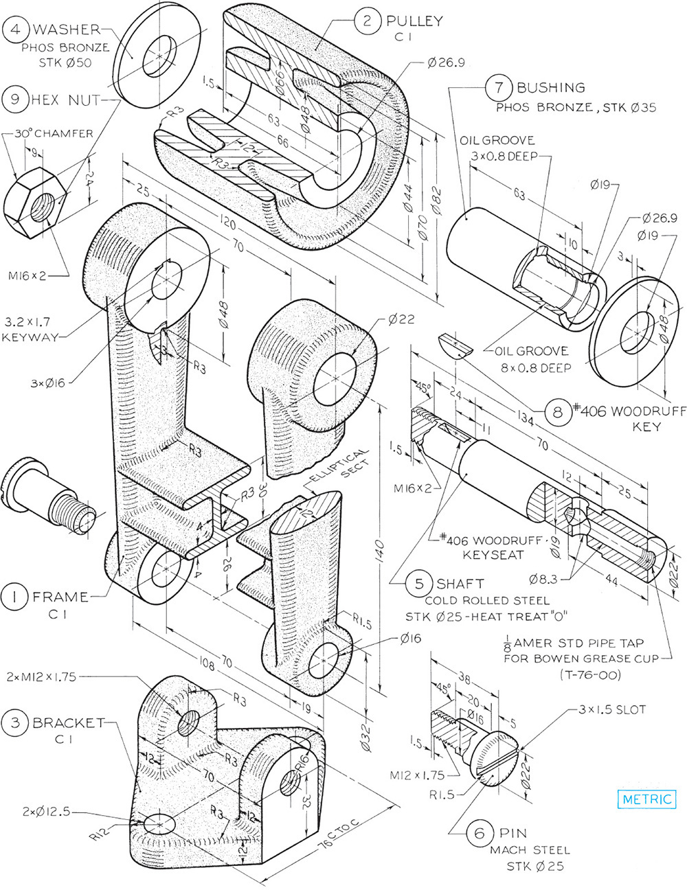
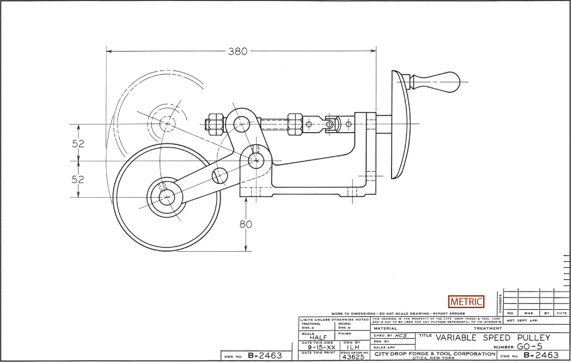
Exercise 14.39 For the belt tightener, draw the following. (1) Draw details. (2) Draw assembly. It is assumed that the parts are to be made in quantity, and they are to be dimensioned for interchangeability on the detail drawings. Use tables in Appendices 4–7 for limit values. Design as follows. (a) Bushing fit in pulley: locational interference fit. (b) Shaft fit in bushing: free-running fit. (c) Shaft fits in frame: sliding fit. (d) Pin fit in frame: free-running fit. (e) Pulley hub length plus washers fit in frame: allowance 0.13 and tolerances 0.10. (f) Make bushing 0.25 mm shorter than pulley hub. (g) Bracket fit in frame: Same as (e).
Exercise 14.40 For the milling jack, draw the following. (1) Draw details. (2) Draw assembly. If assigned, convert dimensions to metric or decimal-inch system.

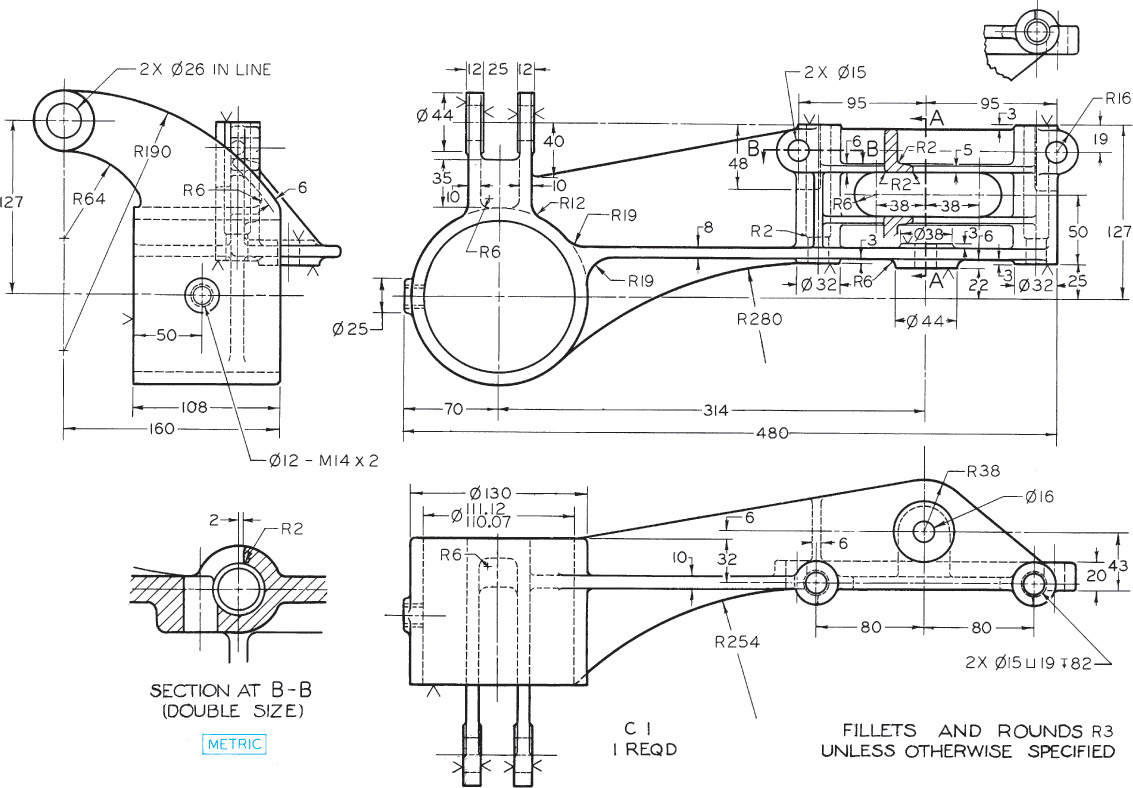
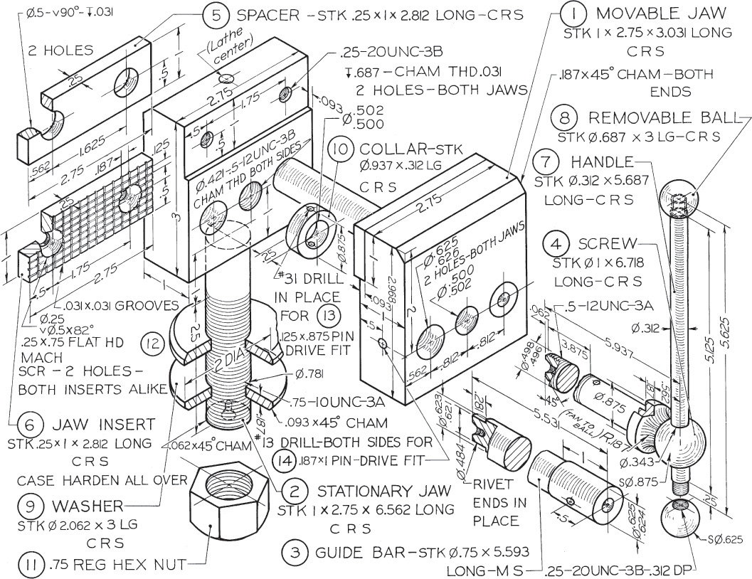
Exercise 14.41 For the connecting bar, draw the following. (1) Draw details. (2) Draw assembly. If assigned, convert dimensions to metric or decimal-inch system.
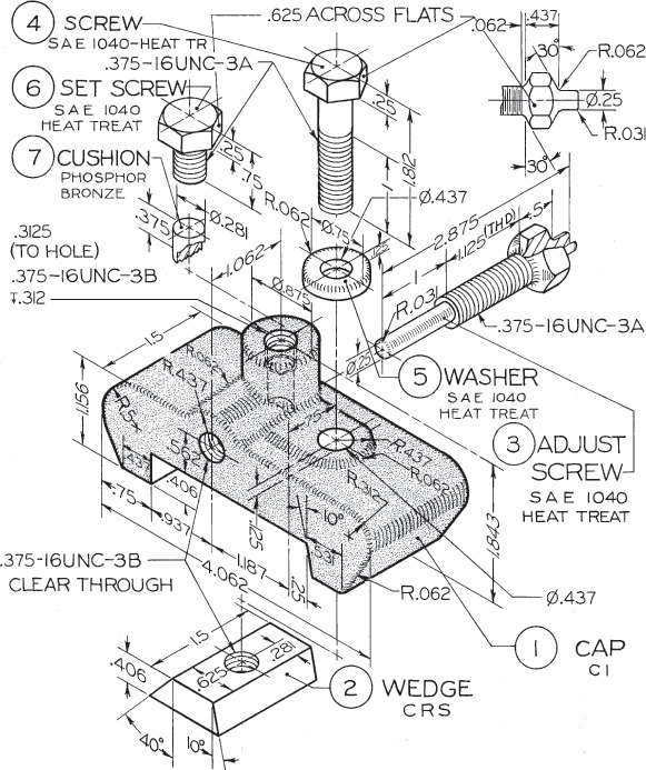
Exercise 14.42 For the clamp stop, draw the following. (1) Draw details. (2) Draw assembly. If assigned, convert dimensions to decimal-inch system or redesign for metric dimensions.
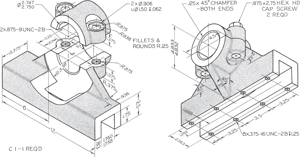
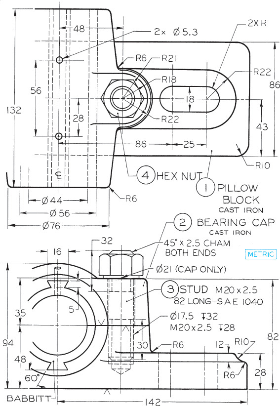
Exercise 14.43 For the pillow block bearing, draw the following. (1) Draw details. (2) Draw assembly. If assigned, complete with dimensions.
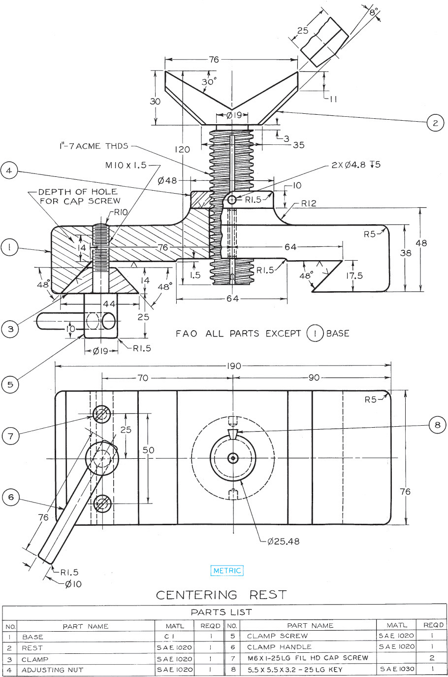
Exercise 14.44 For the centering rest, draw the following. (1) Draw details. (2) Draw assembly. If assigned, complete with dimensions.

Exercise 14.45 For the pipe vise, draw the following. (1) Draw details. (2) Draw assembly. To obtain dimensions, take distances directly from figure with dividers; then set dividers on printed scale and read measurements in millimeters or decimal inches as assigned. All threads are general-purpose metric threads (see Appendix 14) or unified coarse threads except the American National Standard pipe threads on handle and handle caps.
Exercise 14.46 For the tap wrench, draw the following. (1) Draw details. (2) Draw assembly. If assigned, use unidirectional two place decimals for all fractional dimensions or redesign for metric dimensions.
Exercise 14.47 For the machinist’s vise, draw the following. (1) Draw details. (2) Draw assembly. If assigned, use standard symbols and unidirectional two-place decimals for all fractional dimensions or redesign for metric dimensions.
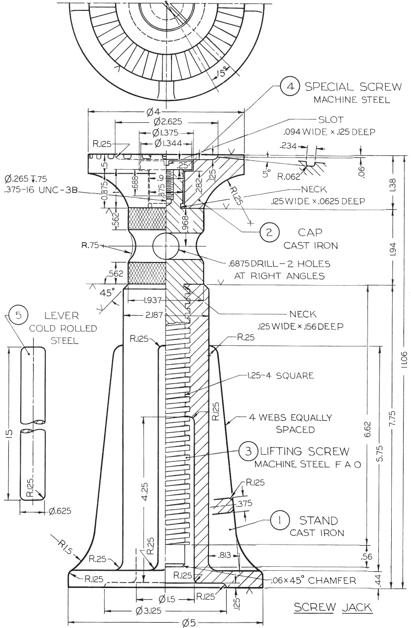
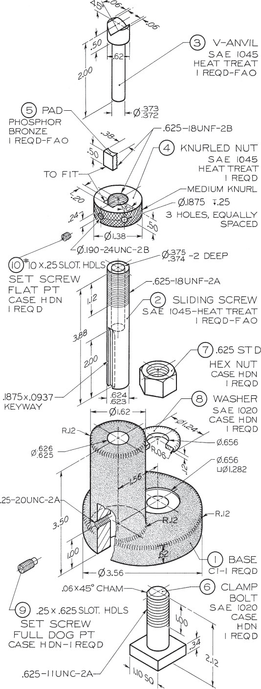
Exercise 14.48 For the screw jack, draw the following. (1) Draw details. (2) Draw assembly. If assigned, convert dimensions to decimal inches or redesign for metric dimensions.
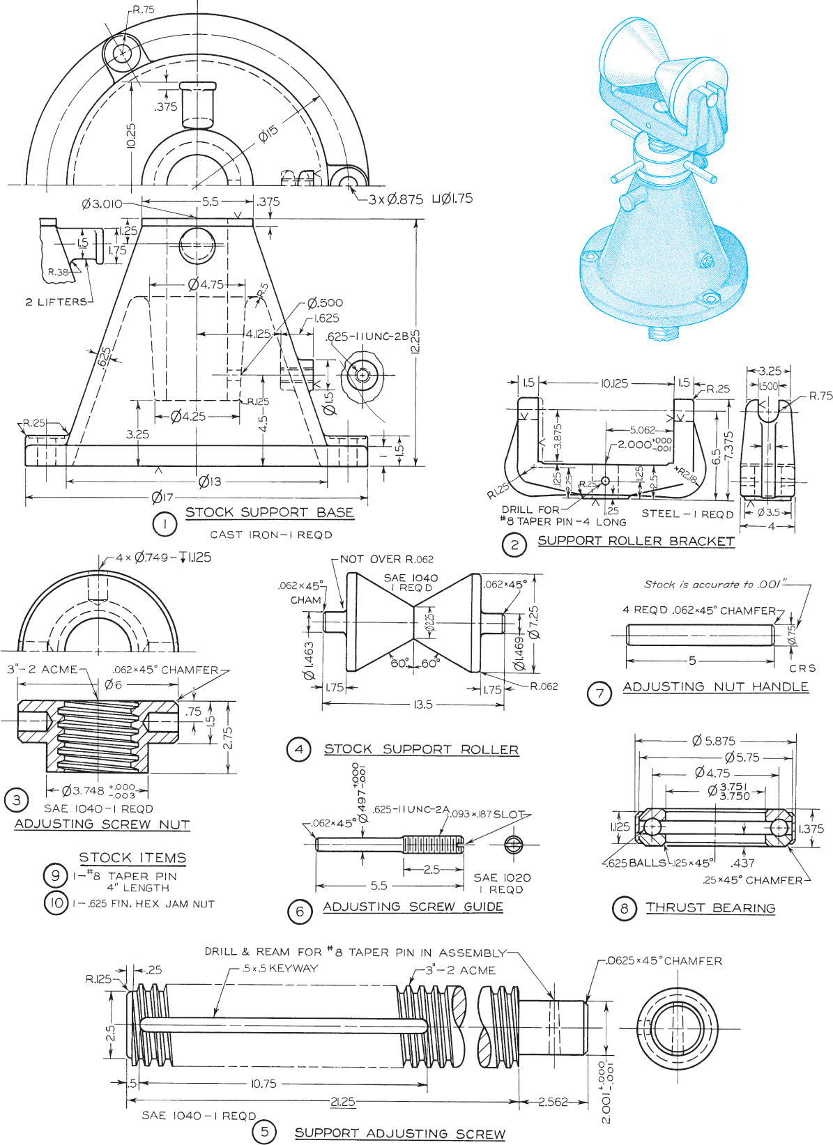
Exercise 14.49 For the stock bracket for cold saw machine, draw the following. (1) Draw details. (2) Draw assembly. If assigned, use unidirectional decimal dimensions or redesign for metric dimensions.
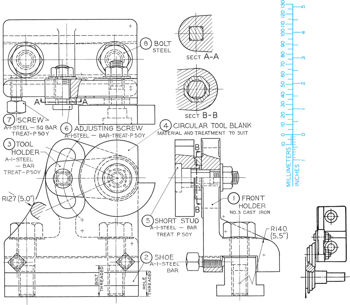
Exercise 14.50 For the front circular forming cutter holder, draw the following. (1) Draw details. (2) Draw assembly. To obtain dimensions, take distances directly from figure with dividers and set dividers on printed scale. Use metric or decimal-inch dimensions as assigned.
Exercise 14.51 For the machine vise on the facing page, draw the following. (1) Draw details. (2) Draw assembly. If assigned, convert dimensions to the decimal-inch system or redesign with metric dimensions.
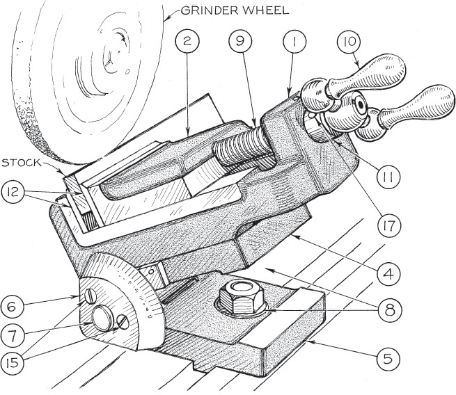
Exercise 14.52 For the grinder vise, draw the following. (1) Draw details. (2) Draw assembly. If assigned, convert dimensions to decimal inches or redesign with metric dimensions. See part details on the following pages.
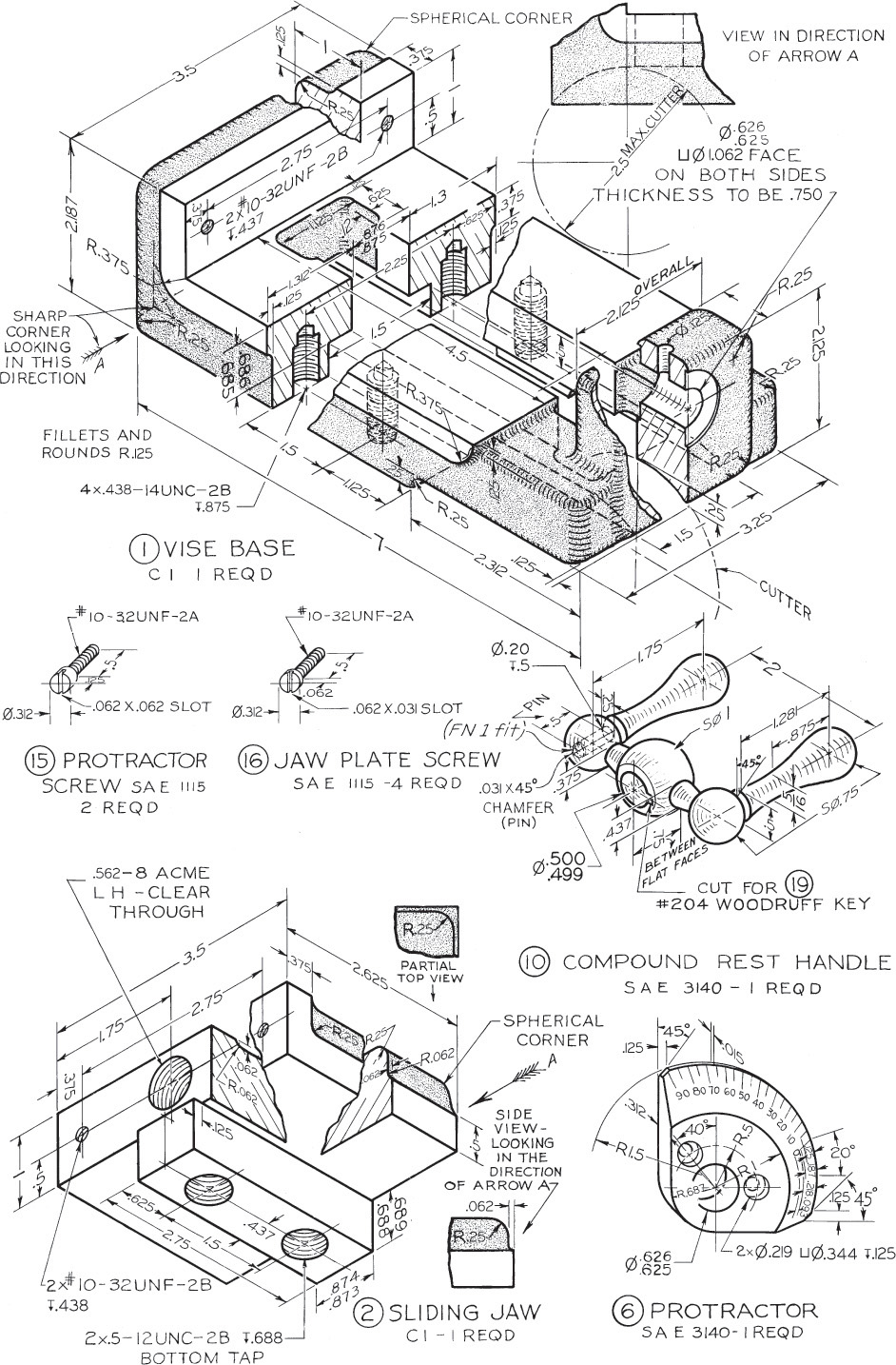
Exercise 14.52 Grinder vise, continued.

Exercise 14.52 Grinder vise, continued.
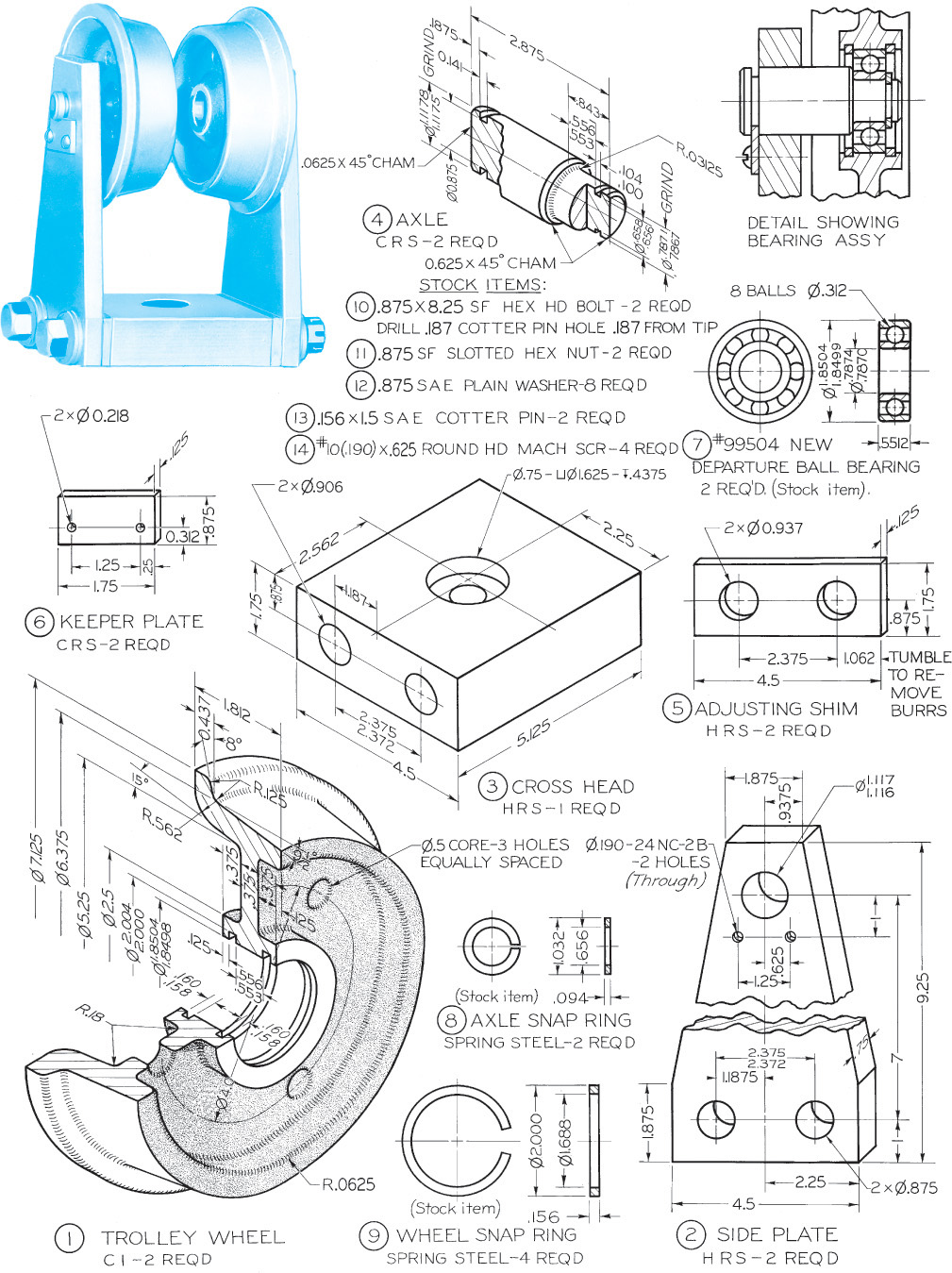
Exercise 14.53 For the trolley, draw the following. (1) Draw details, omitting parts 7–14. (2) Draw assembly. If assigned, convert dimensions to decimal inches or redesign for metric dimensions.

Exercise 14.54 For the arbor press, draw the following. (1) Draw details. (2) Draw assembly. If assigned, convert dimensions to decimal inches or redesign for metric dimensions.

Exercise 14.55 For the forming cutter holder, draw the following. (1) Draw details using decimal or metric dimensions. (2) Draw assembly. Above layout is half size. To obtain dimensions, take distances directly from figure with dividers and double them. At top-left is shown the top view of the forming cutter holder in use on the lathe.

Exercise 14.56 For the milling fixture for clutch arm, draw the following. (1) Draw details using the decimal-inch system or redesign for metric dimensions, if assigned. (2) Draw assembly.
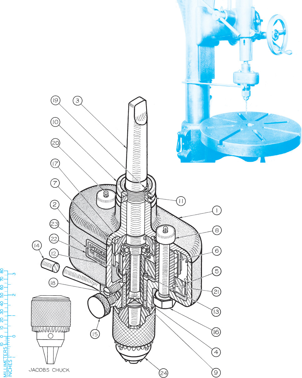
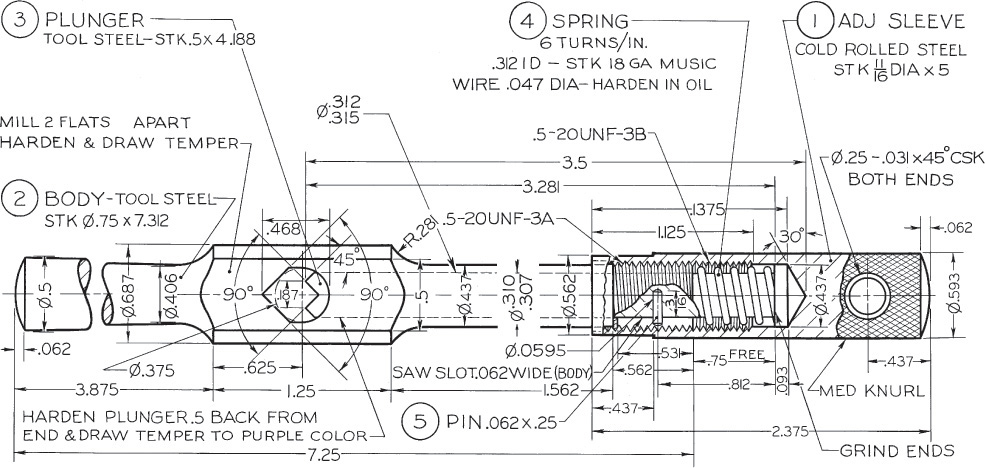
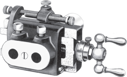
Exercise 14.57 For the drill speeder, draw the following. (1) Draw details. (2) Draw assembly. If assigned, convert dimensions to decimal inches or redesign with metric dimensions. See part details on the following pages.

Exercise 14.57 Drill speeder, continued.
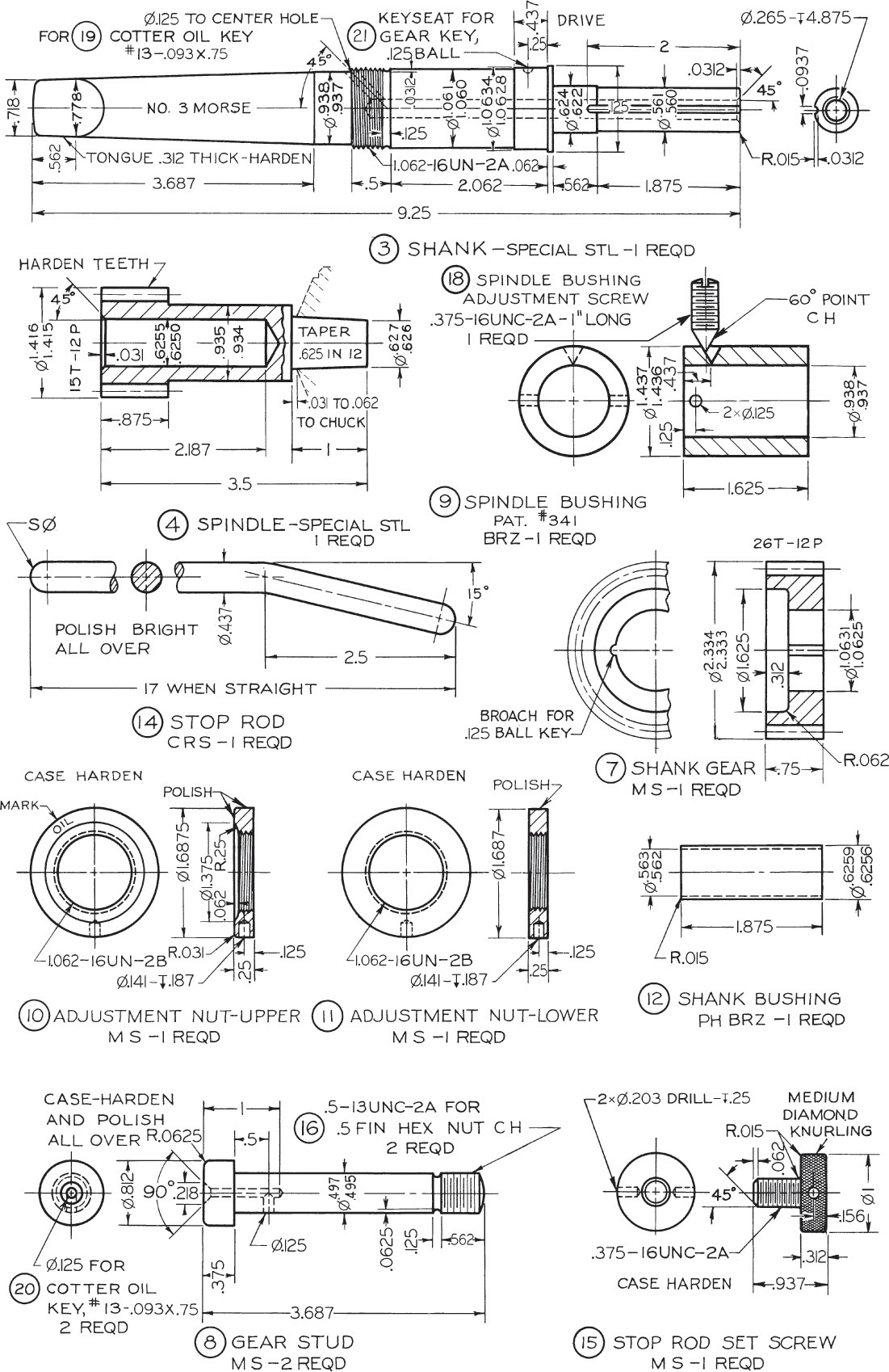
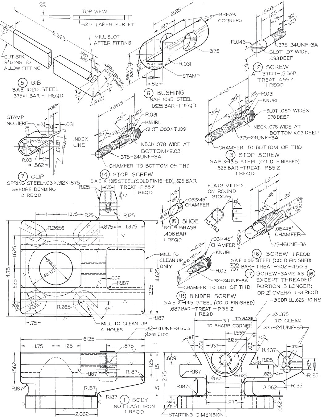
Exercise 14.57 Drill speeder, continued.

Exercise 14.58 For the vertical slide tool, draw the following. (1) Draw details. If assigned, convert dimensions to decimal inches or redesign for metric system. (2) Draw assembly. Take given top view as front view in the new drawing; then add top and right-side views. If assigned, use unidirectional dimensions. See more part details on the following page.
Exercise 14.58 Vertical slide tool, continued.
Exercise 14.59 For the slide tool, draw the following. Consult part information on the following pages to: (1) Draw details using decimal inch dimensions or redesign with metric dimensions, if assigned. (2) Make an assembly drawing of this slide tool.
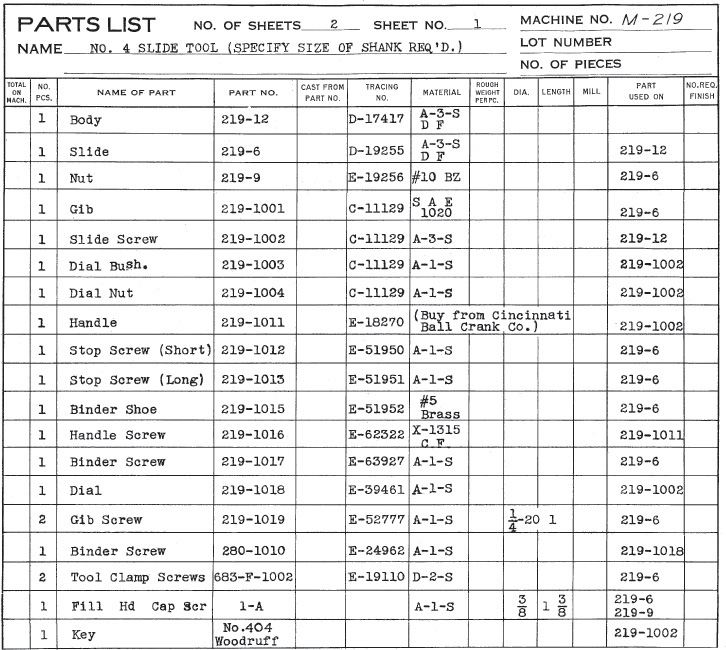
Exercise 14.59 Slide tool, continued. Parts List.
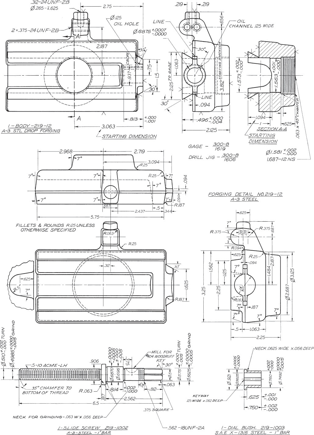
Exercise 14.59 Slide tool, continued.
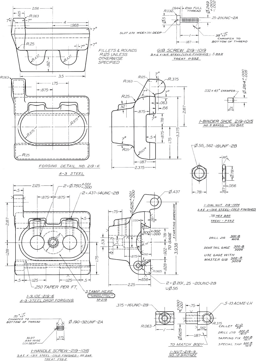
Exercise 14.59 Slide tool, continued.
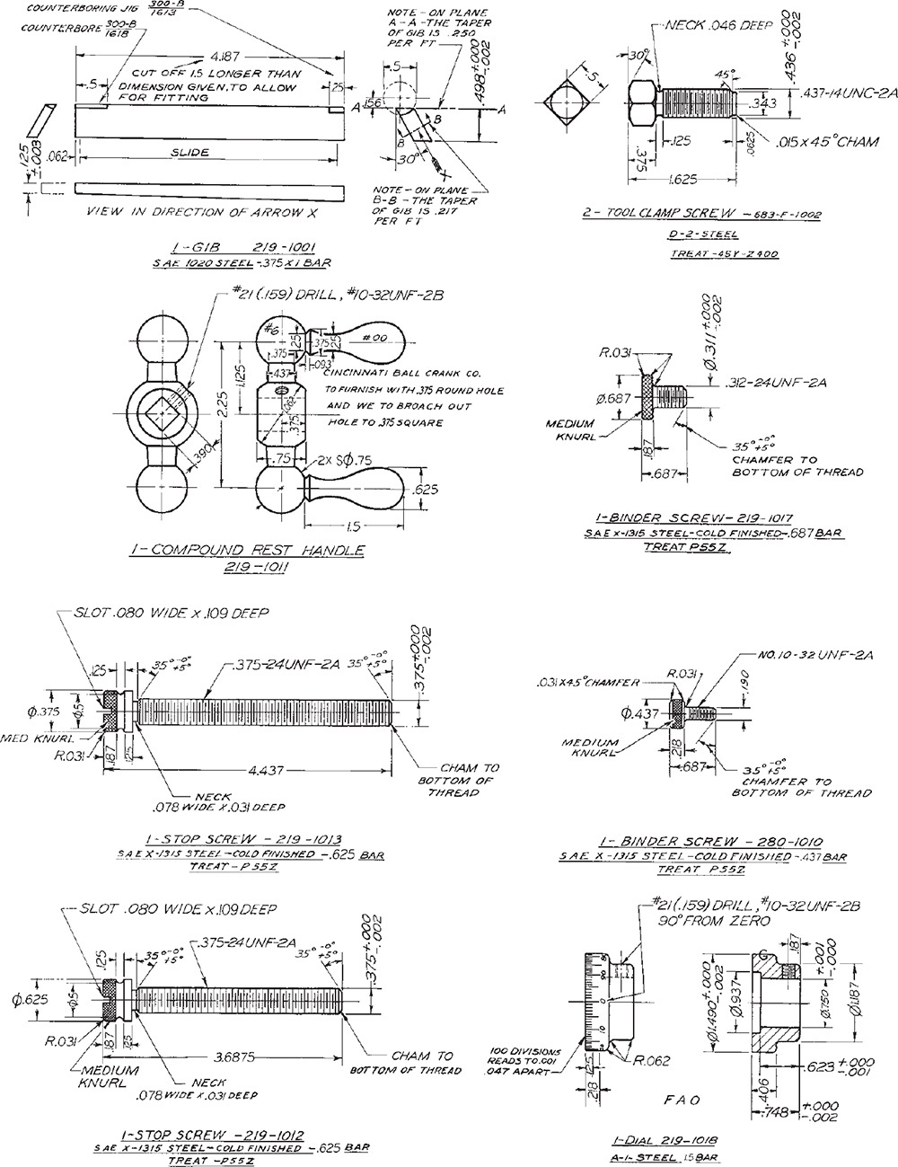
Exercise 14.59 Slide tool, continued.
Exercise 14.60 For the “any angle” tool vise, draw the following. (1) Draw details using decimal-inch dimensions or redesign with metric dimensions, if assigned. (2) Draw assembly. See more part details on the following page.

Exercise 14.60 The “any angle” tool vise, continued.

Exercise 14.61 For the fixture for centering connecting rod, draw the following. Consult part information on the following pages to: (1) Draw details using decimal-inch dimensions or redesign with metric dimensions, if assigned. (2) Draw assembly.
Exercise 14.61 Fixture for centering connecting rod, continued.
Exercise 14.61 Fixture for centering connecting rod, continued.
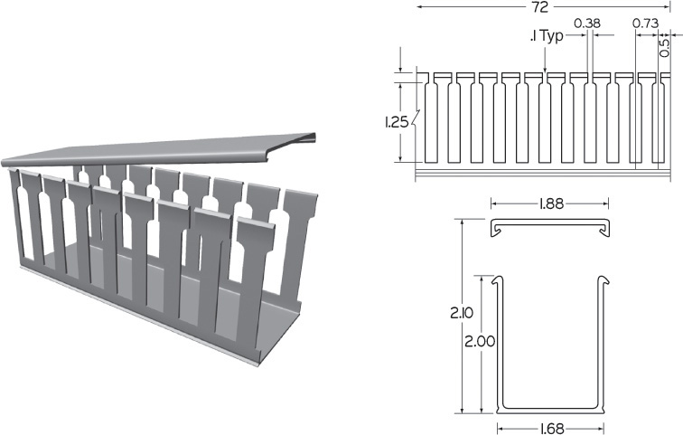
Exercise 14.62 For the plastic open slot wiring duct, front and side views, redraw with metric dimensions, reducing the size by 3.