
Chapter Sixteen. Gears and Cams
Objectives
After studying the material in this chapter, you should be able to:
1. Define the characteristics of a spur gear, worm gear, and bevel gear.
2. Calculate the gear ratio and rpm of two mating gears, given the pitch diameters.
3. Define the principal spur gear terms.
4. Draw a spur gear.
5. Describe the relationship between a cam profile and a displacement diagram.
6. Draw a cam profile, given a displacement profile drawing.
7. List the types of cam followers.
Refer to the following standards:
• ANSI Y14.7.1 Gear Drawing Standards, Part 1: For Spur, Helical, Double Helical, and Rack
• ANSI Y14.7.2 Gear and Spline Drawing Standards, Part 2: Bevel and Hypoid Gears
• AGMA 933-B03 Basic Gear Geometry


Understanding Gears
Gears are used to transmit power and rotating or reciprocating motion from one machine part to another. They may be classified according to the position of the shafts that they connect. Parallel shafts, for example, may be connected by spur gears, helical gears, or herringbone gears. Intersecting shafts may be connected by bevel gears having either straight, skew, or spiral teeth. Nonparallel, nonintersecting shafts may be connected by helical gears, hypoid gears, or a worm and worm gear. A spur gear meshed with a rack will convert rotary motion to reciprocating motion.
ASME/AGMA publishes detailed standards for gear design and drawing. Refer to these standards for current design specification and inspection practices for all gear types discussed in this chapter.
Using Gears to Transmit Power
The friction wheels shown in Figure 16.1a transmit motion and power from one shaft to another parallel shaft. However, friction wheels are subject to slipping, and a great deal of pressure is required between them to create the necessary frictional force; therefore, they are usually used for low-power applications, such as CD ROM drives. Spur gears (Figure 16.1b) have teeth on the cylindrical surfaces that fit together and transmit the same motion and power without slipping and with reduced bearing pressures.
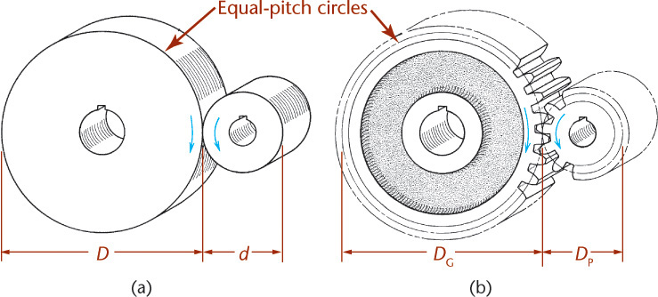
If a friction wheel of diameter D turns at n rpm (revolutions per minute), the linear velocity, v, of a point on its periphery will be πDn, because πD = c (circumference).
Example

The pitch circles of a pair of mating spur gears correspond exactly to the outside diameters of the friction wheels, and because the gears turn in contact without slipping, they must have the same linear velocity at the pitch line.
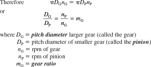
The gear ratio is also expressed as nP/nG or DG/DP.
Example
Example
For the same gear pair, let nP = 1725 rpm. Find nG.

The teeth on mating gears must be of equal width and spacing, so the number of teeth on each gear, N, is directly proportional to its pitch diameter, or
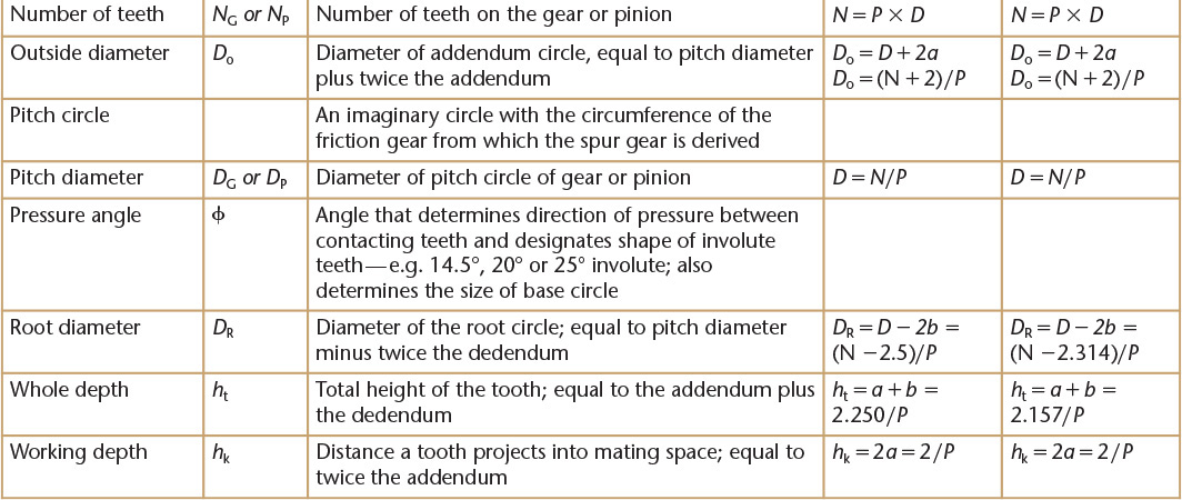
Spur Gear Definitions and Formulas
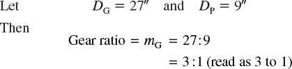
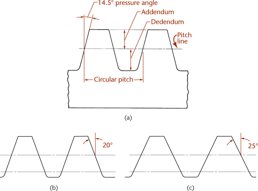
Proportions and shapes of gear teeth are well standardized, and the terms illustrated and defined in Figure 16.2 are common to all spur gears. The dimensions relating to tooth height are for full-depth 14.5° (which are becoming outmoded) or for 20° or 25° involute teeth. Of course, meshing gears must have the same pressure angle.

To make gears operate smoothly with a minimum of noise and vibration, the curved surface of the tooth profile uses a definite geometric form. The most common form in use today is the involute profile shown in Figure 16.4. (The word involute means “rolled inward.”)
16.1 Constructing a Base Circle
The involute tooth form depends on the pressure angle, which was ordinarily 14.5° and is now typically 20° or 25°. This pressure angle determines the size of the base circle; from this the involute curve is generated.
To calculate the base circle for the spur gear as shown in Figure 16.3, follow these steps. At any point on the pitch circle, such as point P (the pitch point) draw a line tangent to the pitch circle; draw a second line through P at the required pressure angle (frequently approximated at 15° on the drawing). This line is called the line of contact. Next, draw a line perpendicular to the line of contact from the center, C. Then, draw the base circle with radius CJ tangent to the line of contact at J.

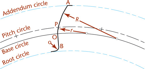
16.2 The Involute Tooth Shape
If the exact shape of the tooth is desired, the portion of the profile from the base circle to the addendum circle (outside diameter) can be drawn as the involute of the base circle. In Figure 16.4, the tooth profile from A to O is an involute of the base circle. The part of the profile below the base circle, line OB, is drawn as a radial line (a straight line drawn from the gear center) that terminates in the fillet at the root circle. The fillet should be equal in radius to one and a half times the clearance from the tip of the tooth to the bottom of the mating space.

16.3 Approximate Involute Using Circular Arcs
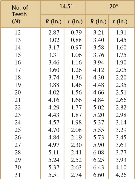
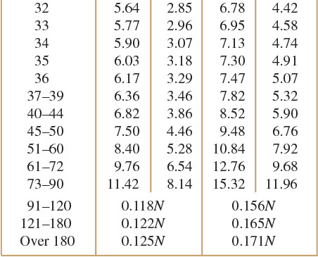
Involute curves can be closely approximated with two circular arcs, as shown in Figure 16.6. This method, originally devised by G. B. Grant, uses a table of arc radii, an involute odontograph, for gears with various numbers of teeth. To use this method, draw the base circle as described above, and set off the spacing of the teeth along the pitch circle. Then, draw the face of the tooth from P to A with the face radius R, and draw the portion of the flank from P to O with the flank radius r. Draw both arcs from centers located on the base circle. The table in Figure 16.6 gives the correct face and flank radii for gears of one diametral pitch. For other pitches, divide the values in the table by the diametral pitch. For gears with more than 90 teeth, use a single radius (let R = r) computed from the appropriate formula given in Figure 16.6, then divide by diametral pitch. Below the base circle, complete the flank of the tooth with a radial line OB and a fillet. (A typical fillet radius is 1.5 times the clearance.)

16.5 Shaded model of Involute Shaped Spur Gear Teeth. It is not typical to model gear teeth in detail, as doing so creates an unnecessarily large and complex model.
16.4 Spacing Gear Teeth
Suppose that number of teeth (N) = 20 and diametral pitch (P) = 4 for a 14.5° involute tooth. The values from Figure 16.6 are R = 4.02 and r = 1.56. These must be divided by P; yielding R = 4.02/4 = 1.005″ and r = 1.56/4 = 0.39″.
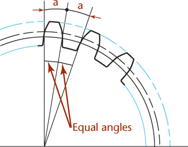
Space the teeth around the periphery by laying out equal angles (Figure 16.7). The number of spaces should be 2N, twice the number of teeth, to make the space between teeth equal to the tooth thickness at the pitch circle. In the example, because N = 20, a = 360°/2N = 360°/40 = 9°, the angle subtended by each tooth and each space.
Tip
The Divide command in the AutoCAD software is very handy for dividing a circle or other geometry into any number of equal divisions. You can also use it to insert a block at the same time. A polar array is another useful tool for creating gears.
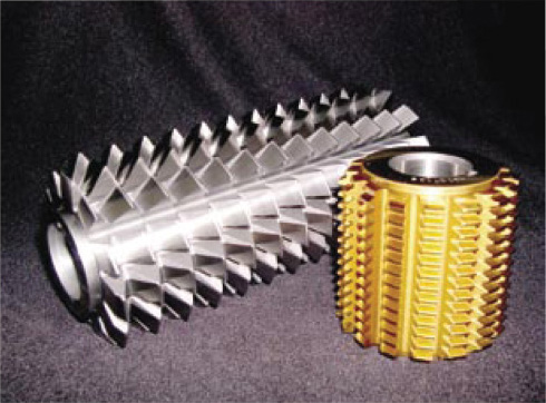
Involute Gear Hob. Spur gears with involute tooth shapes are usually manufactured using a hobbing machine. This machine cuts gear teeth by rotating the gear blank and a cutter like the one shown at a fixed speed ratio. The cross-sectional profile of the sides of the teeth on the cutter generates the involute tooth shape for the gear. Very small gears normally must be milled instead. (Courtesy of Hobsource.)
16.5 Rack Teeth
Gear teeth formed on a flat surface are called a rack. In the involute system, the sides of rack teeth are straight and are inclined at an angle equal to the pressure angle. To mesh with a gear, the linear pitch of the rack must be the same as the circular pitch of the gear, and the rack teeth must have the same height proportions as the gear teeth (see Figure 16.8).
16.6 Working Drawings of Spur Gears
A typical working drawing of a spur gear is shown in Figure 16.9. Because the teeth are cut to standard shape, it is not necessary to show individual teeth on the drawing. Instead, draw the addendum and root circles as phantom lines and the pitch circle as a centerline.
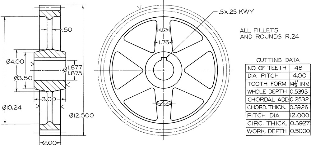
The drawing actually shows only a gear blank—a gear complete except for teeth. Because the machining of the blank and the cutting of the teeth are separate operations, the necessary dimensions are arranged in two groups: the blank dimensions are shown on the views, and the cutting data are given in a note or table.
Before laying out the working drawing, calculate the gear dimensions. For example, if the gear must have 48 teeth of 4 diametral pitch, with 14.5° full-depth involute profile, as in Figure 16.9, calculate the following items in this order: pitch diameter, addendum, dedendum, outside diameter, root diameter, whole depth, chordal thickness, and chordal addendum.
The dimensions shown in Figure 16.9 are the minimum requirements fosr the spur gear. The chordal addendum and chordal thickness are given to aid in checking the finished gear. Other special data may be given in the table, according to the degree of precision required and the manufacturing method.
16.7 Spur Gear Design
Spur gear design normally begins with selecting pitch diameters to suit the required speed ratio, center distance, and space limitations. The size of the teeth (the diametral pitch) depends on the gear speeds, gear materials, horsepower to be transmitted, and the selected tooth form. The complete analysis and design of precision gears is complex and beyond the scope of this textbook, but the chart in Figure 16.10 gives suitable diametral pitches for ordinary cut spur gears.
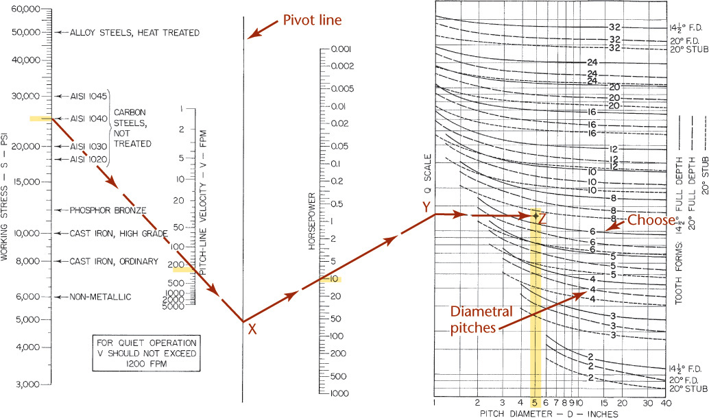
16.10 Chart for design of Cut Spur Gears. The chart is based on the Lewis equation, with the Barth velocity modification, and assumes gear face width equal to three times the circular pitch.
Example Determine the diametral pitch and face width for a 5″ pitch diameter (G10400 carbon steel) pinion with 14.5° full-depth teeth that must transmit 10 hp (horsepower) at 200 rpm.
Calculate the pitch in line velocity V as follows:

On the chart, draw a straight line from 25,000 psi on the working stress scale through 262 fpm on the velocity scale to intersect the pivot line at X. From X, draw a second straight line through 10 on the horsepower scale to intersect the Q scale at Y. From this point, enter the graph of pitches and go to the ordinate for 5″ pitch diameter. The junction point Z falls slightly above the curve for 14.5° full-depth teeth of 6 diametral pitch; hence, choose 6 diametral pitch for the gears.
For good proportions, the face width of a spur gear should be about three times the circular pitch, and this proportion is incorporated in the chart. For 6 diametral pitch, the circular pitch is π/6 or .5236″, and the face width is 3 × .5236 or 1.5708″. This width should be rounded to 1-5/8″ (1.625″).
When both the pinion and the gear are of the same material, the smaller gear is the weaker, and the design should be based on the pinion. When the materials are different, the chart should be used to determine the horsepower capacity of each gear.
16.8 Worm Gears
Worm gears are used to transmit power between nonintersecting shafts that are at right angles to each other. A worm (Figure 16.11) is a screw with a thread shaped like a rack tooth. The worm wheel is similar to a helical gear that has been cut to conform to the shape of the worm for more contact. Worm gearing offers a large speed ratio, since with one revolution a single-thread worm advances the worm wheel only one tooth and a space.

Figure 16.12 shows a worm and a wheel engaged. The section taken through the center of the worm and perpendicular to the axis of the worm wheel shows that the worm section is identical to a rack and that the wheel section is identical to a spur gear. Consequently, in this plane the height proportions of thread and gear teeth are the same as for a spur gear of corresponding pitch.

Pitch (p) The axial pitch of the worm is the distance from a point on one thread to the corresponding point on the next thread measured parallel to the worm axis. The pitch of the worm must be exactly equal to the circular pitch of the gear.
Lead (L) The lead is the distance that the thread advances axially in one turn. The lead is always a multiple of the pitch. Thus, for a single-thread worm, the lead equals the pitch; for a double-thread worm, the lead is twice the pitch, and so on.
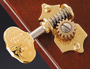
A Waverly Guitar Tuner. Worms are often designed so they can easily turn the gear, but the gear cannot turn the worm. Guitar machines, often called tuners, use worm gears so that the guitar can be tuned by turning the worm, but the strings are kept taut, as the gear cannot turn the worm. (Courtesy of Stewart-MacDonald Company.)
Lead angle (λ)
The lead angle is the angle between a tangent to the helix at the pitch diameter and a plane perpendicular to the axis of the worm. The lead angle can be calculated from
where
DW = pitch diameter of the worm
The speed ratio of worm gears depends only on the number of threads on the worm and the number of teeth on the gear. Therefore,

where

NG = number of teeth on the gear
NW = number of threads on the worm
For 14.5° standard involute teeth and single-thread or double-thread worms, the following proportions are the recommended practice of the AGMA. All formulas are expressed in terms of circular pitch p instead of diametral pitch P. It is easier to machine the worm and the hob used to cut the gear if the circular pitch has an even rational value such as 5/8″.
|
For the worm: |
|
|
Pitch diameter |
DW = 2.4 p + 1.1* |
|
Whole depth |
ht = 0.686 p |
|
Outside diameter |
Do = DW Dt + 0.4775p |
|
Face radius |
Rf = .5DW – 0.318p |
|
Rim radius |
Rr = .5DW + p |
|
Face width |
F = 2.38p + 0.25 |
|
Center distance |
C = .5(DG + DW) |
16.9 Working Drawings of Worm Gears
In an assembly drawing, the engaged worm and gear can be shown as in Figure 16.12, but usually the gear teeth are omitted and the gear blank represented conventionally, as shown in the lower half of the circular view. On detail drawings, the worm and gear are usually drawn separately, as shown in Figures 16.13 and 16.14. Although their dimensioning depends on the production method, it is standard practice to dimension the blanks on the views and give the cutting data in a table, as shown. Note dimensions that closely affect the engagement of the gear and worm have been given as three-place decimal or limit dimensions; other dimensions, such as rim radius, face lengths, and gear outside diameter, have been rounded to convenient two-place decimal values.


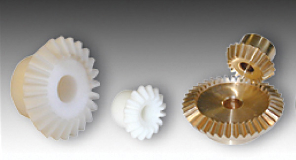
16.10 Bevel Gears
Bevel gears (Figure 16.15) are used to transmit power between shafts whose axes intersect. The analogous friction drive would consist of a pair of cones with a common apex at the point where their axes intersect, as in Figure 16.16. The axes may intersect at any angle, but right angles are most common. Bevel gear teeth have the same involute shape as teeth on spur gears, but they are tapered toward the cone apex; hence, the height and width of a bevel gear tooth vary with the distance from the cone apex. Spur gears are interchangeable (a spur gear of given pitch will run properly with any other spur gear of the same pitch and tooth form), but this is not true of bevel gears, which must be designed in pairs and will run only with each other.

The speed ratio of bevel gears can be calculated from the same formulas given for spur gears.
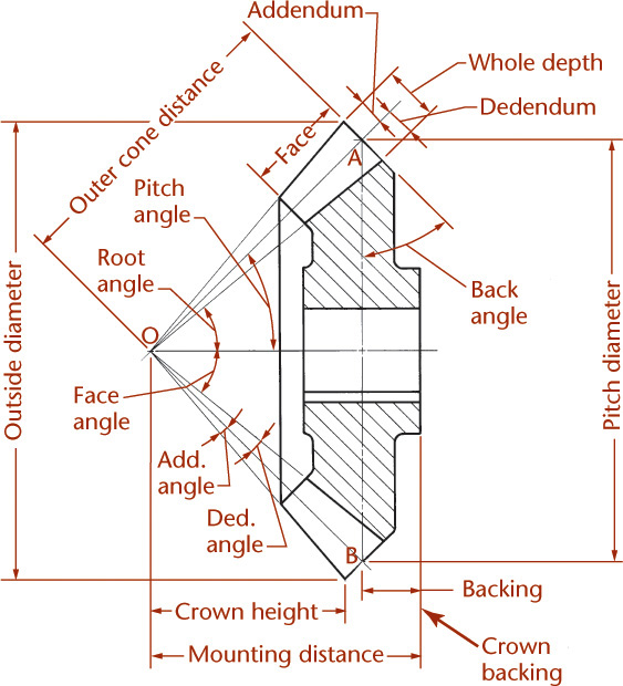
16.11 Bevel Gear Definitions and Formulas
Because the design of bevel gears is very similar to that of spur gears, many spur gear terms are applied with slight modification to bevel gears. Just as in spur gears, the pitch diameter D of a bevel gear is the diameter of the base of the pitch cone, the circular pitch p to the teeth is measured along this circle and the diametral pitch P is also based on this circle.
The important dimensions and angles of a bevel gear are illustrated in Figure 16.17. The pitch cone is shown as the triangle AOB, and the pitch angle is half of angle AOB. The root and face angle lines do not actually converge at point O but are often drawn as if they do for simplicity. Figure 16.17 shows that the pitch angle of each gear depends on the relative diameters of the gears. When the shafts are at right angles, the sum of the pitch angles for the two mating gears equals 90°.
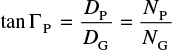
Therefore, the pitch angles, Γ (gamma), are determined from the following equations:
and
In the simplified formulas given here, tooth proportions are assumed equal on both gears, but in modern practice bevel gears are often designed with unequal addenda and unequal tooth thicknesses to balance the strength of gear and pinion. Refer to AGMA standards for more details.
Terms for bevel gear definitions and formulas are given in Table 16.1.
Table 16.1 Bevel Gear Terms, definitions, and Formulas
Term |
Symbol |
Definition |
Formula |
Addendum |
a |
Distance from pitch cone to top of tooth; measured at large |
a = 1{{#}}8729;P |
Addendum angle |
α |
Angle subtended by addendum; same for gear and pinion |
tan α = a{{#}}8729;A |
Back angle |
Usually equal to the pitch angle |
||
Backing |
Y |
Distance from base of pitch cone to rear of hub |
|
Chordal addendum Chordal thickness |
|
For bevel gears, the formulas given for spur gears can be used if D is replaced by D {{#}}8729;cos Γ and N is replaced by N cos Γ |
|
Crown backing |
Z |
More practical than backing for shop use; dimension Z given on drawings instead of Y |
Z = Y + a sin Γ |
Crown height |
X |
Distance, parallel to gear axis, from cone apex to crown of the gear |
X = .5Do{{#}}8729;tan Γo |
Dedendum |
b |
Distance from pitch cone to bottom of tooth; measured at |
b = 1.188{{#}}8729;P |
Dedendum angle |
δ |
Angle subtended by dedendum; same for gear and pinion |
tan δ =b{{#}}8729;A |
Face angle |
Γo |
Angle between top of teeth and the gear axis |
Γo = Γ + α |
Face width |
F |
Should not exceed A{{#}}8729;3 or 10{{#}}8729;P, whichever is smaller |
|
Mounting distance |
M |
A dimension used primarily for inspection and assembly purposes |
M = Y + .5D{{#}}8729;tan Γ |
Outer cone distance |
A |
Slant height of pitch cone; same for gear and pinion |
A = D{{#}}8729;(2 sin Γ) |
Outside diameter |
Do |
Diameter of outside or crown circle of the gear |
Do = D + 2a cos Γ |
Pitch diameter |
DG |
Diameter of base of pitch cone of gear |
DG = NG{{#}}8729;P |
DP |
Diameter of base of pitch cone of pinion |
DP = NP{{#}}8729;P |
|
Root angle |
ΓR |
Angle between the root of the teeth and the gear axis |
ΓR = Γ − δ |
16.12 Working Drawings of Bevel Gears
Like those for spur gears, working drawings of bevel gears give only the dimensions of the gear blank. Data necessary for cutting the teeth are given in a note or table. A single sectional view will usually provide all necessary information (Figure 16.18). If a second view is required, only the gear blank is drawn, and the tooth profiles are omitted. Two gears are shown in their operating relationship. On detail drawings, each gear is usually drawn separately, as in Figure 16.17, and fully dimensioned. Placement of the gear-blank dimensions depends largely on the manufacturing methods used in producing the gear, but the scheme shown is commonly followed.

CAD at Work: Stock Gear Models and Drawings
A great website where you can find stock models for gears is the Stock Drive Products/Sterling Instruments site at sdp-si.com (Figure A). Once you have registered, you can search their site for useful standard parts that you might purchase for a design. After you have located a part, you can download 2D or 3D CAD data. Figure B shows the compatible file types available for download. Detailed data sheets are available for download in PDF format. You can even use a Web viewer to view and rotate the 3D model before you download it (Figure C).
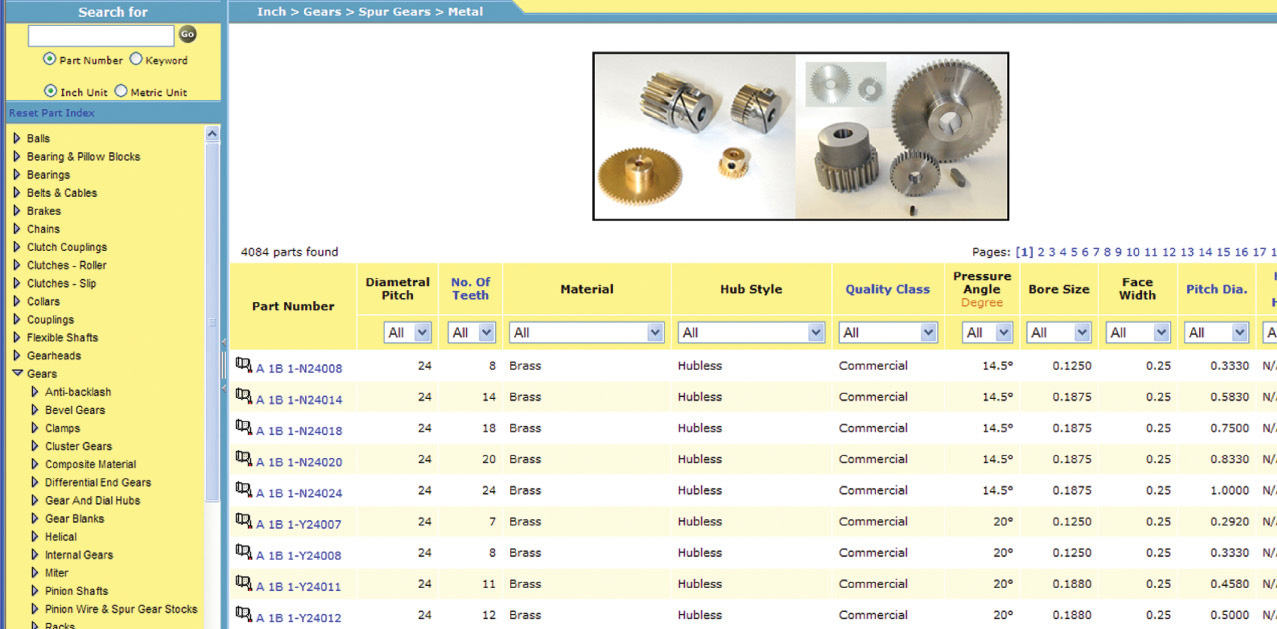
(A) Stock Drive Product/Sterling Instruments provides downloadable CAD models for the parts they sell. (Courtesy of Stock Drive Products/Sterling Instruments.)
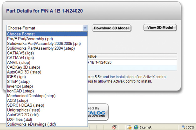
(B) Several CAD formats are available for download. (Courtesy of Stock Drive Products/Sterling Instruments.)
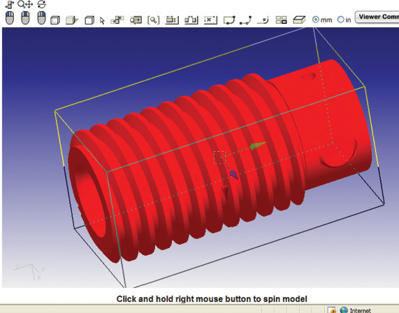
(C) An interactive viewer allows you to view and rotate the 3D model via the Web. (Courtesy of Stock Drive Products/Sterling Instruments.)
When gears are ordered to use as standard parts in an assembly, a detailed gear drawing is not necessary. A table showing the gear information is often sufficient. Simplified representations of the shape—for example, the exterior envelope and/or base curves—may be used to represent the gear.

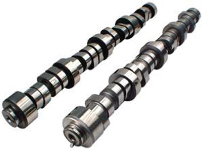
Billet Steel Cams for Ford 4.6/5.4l SOHC V-8 (Courtesy of Crane Cams, Inc.)
16.13 Cams
Cams can produce unusual and irregular motions that would be difficult to produce otherwise. Figure 16.19a shows the basic principle of the cam. A shaft rotating at uniform speed carries an irregularly shaped disk called a cam; a reciprocating member, called the cam follower, presses a small roller against the curved surface of the cam. (The roller is held in contact with the cam by gravity or a spring.) Rotating the cam causes the follower to reciprocate with a cyclic motion according to the shape of the cam profile.

Figure 16.19b shows an automobile valve cam that operates a flat-faced follower. Figure 16.19c shows a disk cam with the roller follower attached to a linkage to transmit motion to another part of the device.
The following sections discuss how to draw a cam profile that will cause the follower to produce the particular motion that is needed.
Most CAD software provides tools to generate cams from design data, so you will not typically draw them manually. However the general principle is helpful when using these design tools.
16.14 Displacement Diagrams
Because the motion of the follower is your first concern, its rate of speed and its various positions should be carefully planned in a displacement diagram before the cam profile is constructed. A displacement diagram (Figure 16.20) is a curve showing the displacement of the follower as ordinates on a baseline that represents one revolution of the cam. Draw the follower displacement to scale, but you can use any convenient length to represent the 360° of cam rotation.

The motion of the follower as it rises or falls depends on the shape of the curves in the displacement diagram. In this diagram, four commonly employed types of curves are shown. If a straight line is used, such as the dashed line AD in Figure 16.20, the follower will move with a uniform velocity, but it will be forced to start and stop very abruptly, producing high acceleration and unnecessary force on the follower and other parts. This straight-line motion can be modified as shown in the curve ABCD, where arcs have been introduced at the beginning and at the end of the period.
The curve shown at EF gives harmonic motion to the follower. To manually construct this curve, draw a semicircle with a diameter equal to the desired rise. Divide the circumference of the semicircle into equal arcs. (The number of divisions should be the same as the number of horizontal divisions.) Then, find points on the curve by projecting horizontally from the divisions on the semicircle to the corresponding ordinates.
The parabolic curve shown at GHK gives the follower constantly accelerated and decelerated motion. The half of the curve from G to H is exactly the reverse of the half from H to K. To manually construct the curve HK, divide the vertical height from K to J into distances proportional to 1′, 2′, 3′, or 1, 4, 9, and so on. The number of vertical divisions should be the same as the number of horizontal divisions. Find points on the curve by projecting horizontally from the divisions on the line JK to the corresponding ordinates. The parabolic curve and curves of higher polynomial equations produce smoother follower motion than those of the other curves discussed.
16.15 Cam Profiles
The general method for manually constructing a cam profile is shown in Figure 16.21. The disk cam rotating counterclockwise on its shaft raises and lowers the roller follower, which is constrained to move along the straight line AB. The displacement diagram at the bottom of the figure shows the desired follower motion.

With the follower in its lowest or initial position, the center of the roller is at A, and OA is the radius of the base circle. The diameter of the base circle is determined from design parameters that are not discussed here.
Because the cam must remain stationary while it is being drawn, you can obtain an equivalent rotative effect by imagining that the cam stands still while the follower rotates about it in the opposite direction. Therefore, the base circle is divided into 12 equal divisions corresponding to the divisions used in the displacement diagram. These divisions begin at zero and are numbered in the direction opposite the cam rotation.
The points 1, 2, and so on, on the follower axis AB indicate successive positions of the center of the roller and are located by transferring ordinates such as X and Y from the displacement diagram. Thus, when the cam has rotated 60°, the follower roller must rise a distance X to position 2, and after 90° of rotation, a distance Y to position 3, and so on.
Note that while the center of the roller moved from its initial position A to position 2, for example, the cam rotated 60° counterclockwise. Therefore, point 2 must be revolved clockwise about the cam center O to the corresponding 60° tangent line to establish point 2′. In this position, the complete follower would appear as shown by the phantom outline. Points represent consecutive positions of the roller center, and a smooth curve drawn through these points is called the pitch curve. To obtain the actual cam profile, the roller must be drawn in a number of positions, and the cam profile drawn tangent to the roller circles, as shown. The best results are obtained by first drawing the pitch curve very carefully and then drawing several closely spaced roller circles with centers on the pitch curve, as shown between points 5′ and 6′.
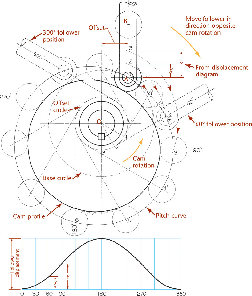
16.16 Offset and Pivoted Cam Followers
If the follower is offset as shown in Figure 16.22, an offset circle is drawn with center O and radius equal to the amount of offset. As the cam turns, the extended centerline of the follower will always be tangent to this offset circle. The equiangular spaces are stepped off on the offset circle, and tangent lines are then drawn from each point on the offset circle, as shown.
If the roller is on a pivoted arm, as shown in Figure 16.23a, then the displacement of the roller center is along the circular arc AB. The height of the displacement diagram (not shown) should be made equal to the rectified length of arc AB. Ordinates from the diagram are then transferred to arc AB to locate the roller positions 1, 2, 3, .... As the follower is revolved about the cam, pivot point C moves in a circular path of radius OC to the consecutive positions C1, C2, and so on. Length AC is constant for all follower positions; hence, from each new position of point C, the follower arc of radius R is drawn as shown at the 90° position. The roller centers 1, 2, 3 are now revolved about the cam center O to intersect the follower arcs at 1′, 2′, 3′. After the pitch curve is completed, the cam profile is drawn tangent to the roller circles.
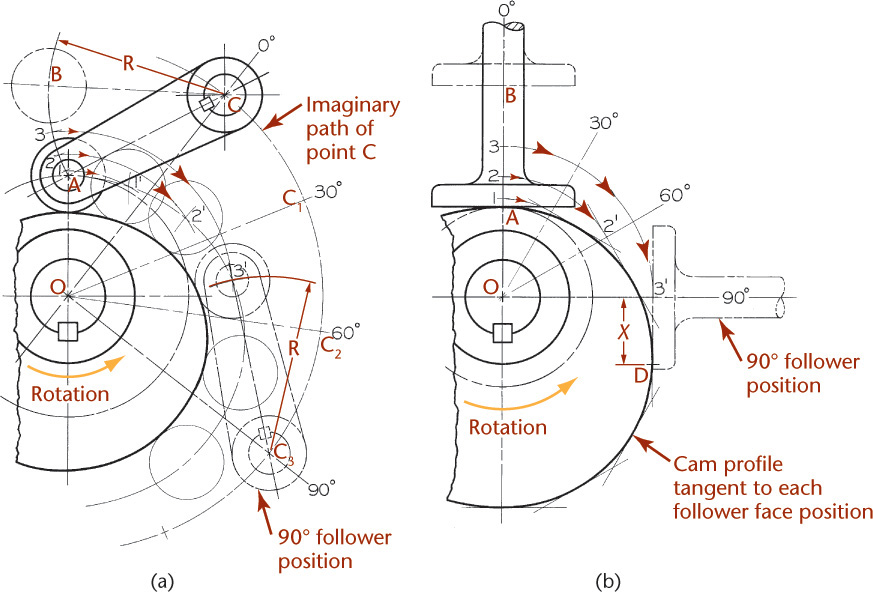
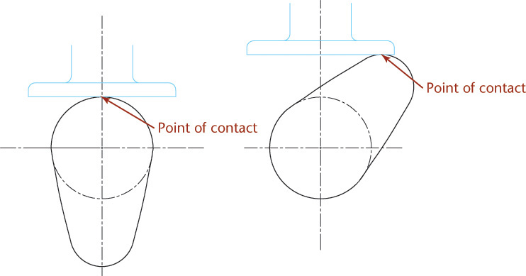
The construction for a flat-faced follower is shown in Figure 16.23b. The initial point of contact is at A, and points 1, 2, 3, represent consecutive positions of the follower face. Then, for the 90° position, point 3 must be revolved 90°, as shown, to position 3′, and the flat face of the follower is drawn through point 3′ at right angles to the cam radius. When this procedure is repeated for each position, the cam profile will be enveloped by a series of straight lines, and the cam profile is drawn inside and tangent to these lines. Note that the point of contact, initially at A, changes as the follower rises. At 90°, for example, contact is at D, a distance X to the right of the follower axis.
16.17 Cylindrical Cams
When the follower movement is in a plane parallel to the camshaft, some form of cylindrical cam must be employed. In Figure 16.24, for example, the follower rod moves vertically parallel to the cam axis as the attached roller follows the groove in the rotating cam cylinder.
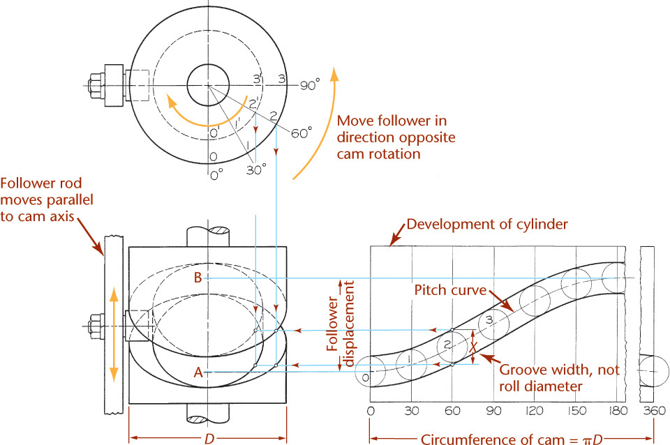
A cylindrical cam of diameter D is required to lift the follower rod a distance AB with harmonic motion in 180° of cam motion and to return the rod in the remaining 180° with the same motion. The displacement diagram is drawn first and conveniently placed directly opposite the front view. The 360° length of the diagram must be made equal to πD so that the resulting curves will be a true development of the outer surface of the cam cylinder. The pitch curve is drawn to represent the required motion, and a series of roller circles is then drawn to establish the sides of the groove tangent to these circles. This completes the development of the outer cylinder and actually provides all information needed for making the cam; hence, it is not uncommon to omit the curves in the front view.
To complete the front view, points on the curves are projected horizontally from the development. For example, at 60° in the development, the width of the groove measured parallel to the cam axis is X, a distance slightly greater than the actual roller diameter. This width X is projected to the front view directly below point 2, the corresponding 60° position in the top view, to establish two points on the outer curves. The inner curves for the bottom of the groove can be established in the same manner, except that the groove width X is located below point 2′, which lies on the inner diameter. The inner curves are only approximate because the width at the bottom of the groove is actually slightly greater than X, but the exact bottom width can be determined only by drawing a second development for the inner cylinder.
16.18 Other Drive Devices
When the distance between drive and driven shafts makes the use of gears impractical, devices such as belt and pulley or chain and sprocket drives are often employed. Layout and detailing standards vary somewhat from one company to another, but design procedures and specification methods may be obtained from almost any good textbook or handbook on mechanical design.
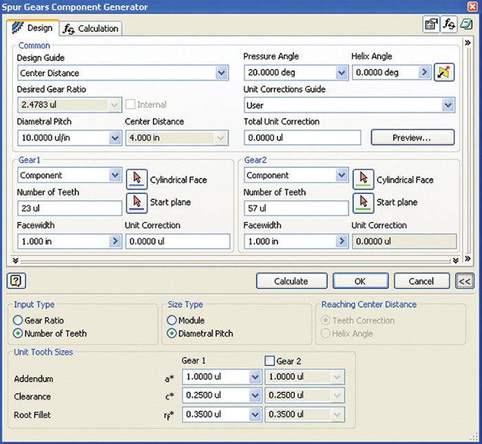
CAD at Work: Gears Using Autodesk Inventor Design Accelerator
When you know the design requirements for a gear pair, you can use a CAD package, such as Autodesk Inventor, to automatically generate the 3D models from the information. It can be very time-consuming to create drawings of gears and cams by hand, whereas using CAD frees you to spend more time on other aspects of your designs.
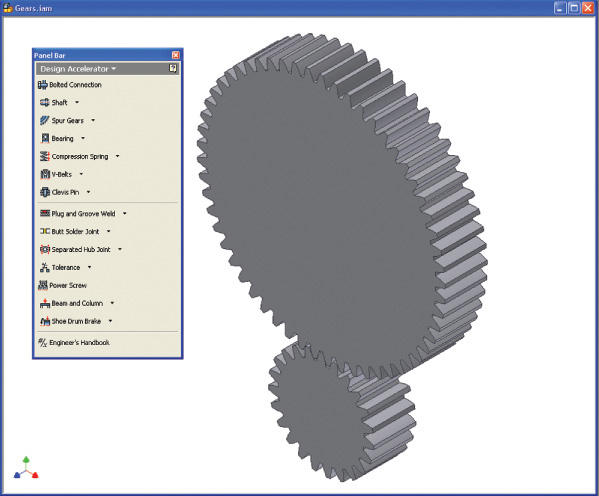
Figure A shows the Autodesk Inventor software’s Spur Gear Component Generator design tab, which you can use to enter the defining details for the gear pair. Clicking the Preview option shows the values and a pictorial representation of the dimensional features for the gear, as shown in Figure B. Once you have entered the data, select OK to generate the 3D models. They are automatically assembled so that the teeth mesh as shown in Figure C. Each gear is a separate part, for which you can list the data and generate the table of information necessary to manufacture the gear. You can also simulate motion to aid in inspecting how your design will function.

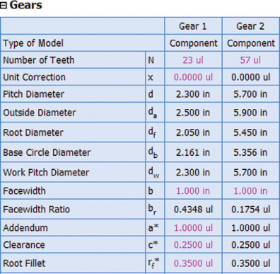
Gear drawings specify the information needed to manufacture the gear using a table. Figure D shows an example of the gear table that can be automatically generated using the software.
The Inventor software’s Design Accelerator has similar tools for designing bolted connections, shafts, spur gears, bevel gears, worm gears, bearings, spring, belts, pins, welds, hubs, beams, and columns, among other useful items.
(Autodesk screen shots reprinted courtesy of Autodesk, Inc.)

Chapter Summary
• Gears transmit power from one rotating shaft to another. The purpose of a gear is to change the rpm, direction, or axis orientation.
• Exact drawings for gears are difficult to draw on paper or with CAD because of complex tooth shape. A table of gear data is typically all that is needed to define the shape.
• Once the mathematical calculations for a gear are complete, the construction of a gear profile is begun by constructing four circles: the addendum circle, pitch circle, base circle, and root circle.
• The involute profile is the most common gear tooth profile.
• Advanced CAD programs can automate the construction of gear teeth.
• The most common gear type is the spur gear. Spur gear axes are parallel to each other.
• The axes of worm gears and bevel gears are positioned 90° to each other.
• Cams change rotating motion into reciprocating motion. The displacement curve defines the linear follower movement as the cam rotates through 360° of rotary motion.
• When gears are ordered as standard parts to use in an assembly, a detailed drawing is not necessary. A table showing the gear information is often sufficient.
Review Questions
1. What is the purpose of a gear?
2. What is the geometric shape most commonly used for a gear tooth profile?
3. What are the four circles used to draw a gear?
4. Which types of gears have shafts that are perpendicular to each other?
5. Describe how to draw a cam profile, given a displacement diagram.
6. What is the purpose of a cam follower?
7. How many total degrees of rotation are shown on a cam displacement diagram?
8. Why is the cam follower position always the same at the starting point and the ending point?
Chapter Exercises
Gearing and Cam Exercises
The following exercises provide practice in laying out and making working drawings of the common types of gears and cams. Where paper sizes are not given, select both scale and sheet layout. If assigned, convert the design layouts to metric dimensions. The instructor may choose to assign specific problems to be completed using CAD.
a. A 12-tooth IDP pinion engages a 15-tooth gear. Make a full-size drawing of a segment of each gear showing how the teeth mesh. Construct the 14.5° involute teeth exactly, noting any points where the teeth appear to interfere. Label gear ratio mG on the drawing. Include dimensions, notes, and cutting data as assigned by your instructor.
b. Follow the instructions for part a but use 13 or 14 teeth, or any number of teeth as assigned by your instructor.
c. Follow the instructions for part a but use 20° stub teeth instead of involute teeth.
d. Follow the instructions for part a but use a rack in place of the 12-tooth pinion.
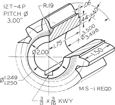
Exercise 16.2 Make a display drawing of the pinion shown in the figure above. Show two views, drawing the teeth by the odontograph method shown in Figure 16.6. Draw double size. Omit dimensions.
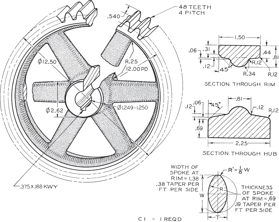
Exercise 16.3 A spur gear has 60 teeth of 5 diametral pitch. The face width is 1.50″. The shaft is 1.19″ in diameter. Make the hub 2.00″ long and 2.25″ in diameter. Calculate all dimensions accurately, and make a working drawing of the gear. Show six spokes, each 1.12″ wide at the hub, tapering to .75″ wide at the rim and .50″ thick. Use your own judgment for any dimensions not given. Draw half size.
Exercise 16.4 Make a pictorial display of the spur gear shown above. Show the gear as an oblique half section, similar to Exercise 16.2. Draw four-times size, reducing the 30° receding lines by half, as in cabinet projection. Draw the teeth by the odontograph method.
Exercise 16.5 Draw the following.
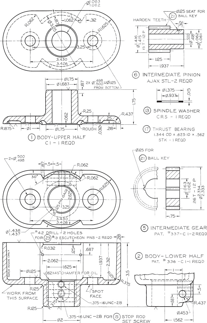
a. Make a pictorial display of the intermediate pinion shown in part 6 in the figure. Show the gear as an oblique half section, similar to Exercise 16.2. Draw four-times size, reducing the 30° receding lines by half, as in cabinet projection. Draw the teeth by the odontograph method.
b. Make a working drawing of the intermediate pinion shown in part 6 of the figure. Check the gear dimensions by calculation.
c. Make a working drawing of the intermediate gear shown in part 5 of the figure. Check the gear dimensions by calculation.
d. Follow instructions for part a, but use the pinion shown in Exercise 16.2.
Exercise 16.6 Draw the following by hand or using CAD, as assigned by your instructor.
a. A pair of bevel gears has teeth of 4 diametral pitch. The pinion has 13 teeth, the gear 25 teeth. The face width is 1.12″. The pinion shaft is .94″ in diameter, and the gear shaft is 1.19″ in diameter. Calculate all dimensions accurately, and make a working drawing showing the gears engaged as in Figure 16.18. Make the hub diameters approximately twice the shaft diameters. Select key sizes from Appendix 20. The backing for the pinion must be .62″, and for the gear 1.25″. Use your own judgment for any dimensions not given.
b. Make a working drawing of the pinion.
c. Make a working drawing of the gear.
d. Show two views of the pinion in part b. Follow the general instructions in that problem.
e. Follow instructions in part a but use 5 diametral pitch and 30 and 15 teeth. The face is 1.00″. Shafts: pinion, 1.00″ diameter; gear, 1.50″ diameter. Backing: pinion, .50″; gear, 1.00″.
f. Follow instructions in part a but use 4 diametral pitch, both gears 20 teeth. Select the correct face width. Shafts: 1.38″ diameter. Backing: 0.75″.

Exercise 16.7 Make a half-scale assembly drawing of the complete unit (a suggested layout with full-size dimensions for view placement is shown). The following full-size dimensions are sufficient to establish the position and general outline of the parts; the minor detail dimensions, web and rib shapes, and fillets and rounds should be designed with the help of the photograph in part a of the figure
The gears are identical in size and are similar in shape to the one in Figure 16.17. There are 24 teeth of 3 diametral pitch in each gear. Face width, 1.50″. Shafts, 2.00″ diameter, extending 7.00″ beyond left bearing, 4.00″ beyond rear (break shafts as shown). Hub diameters, 2.75″. Backing, 1.00″. Hub lengths, 3.25″. The front gear is held by a square gib key and a .38″ set screw. The collar on front shaft next to right bearing is .75″ thick, 2.25″ outside diameter, with a .38″ set screw.
On the main casting, the split bearings are 2.75″ diameter, 3.00″ long, and 10.00″ apart. Each bearing cap is held by two 1/2″ bolts, 3.50″ apart, center to center. Oil holes have a layout for an assembly drawing of a similar unit. Pipe tap for plug or grease cup. Shaft centerlines are 6.50″ above bottom surface, 8.00″ from the rear surface of casting. The main casting is 11.50″ high, and its base is 16.00″ long, 8.75″ wide, and .75″ thick. All webs, ribs, and walls are uniformly .50″ thick. In the base are eight holes (not shown in the photograph) for 1/2″ bolts, two outside each end, and two inside each end.
First block in the gears in each view, then block in the principal main casting dimensions. Fill in details only after principal dimensions are clearly established.
a. The worm and worm gear shown in Figure 16.12 have a circular pitch of .62″, and the gear has 32 teeth of 14.5° involute form. The worm is double threaded. Make an assembly drawing similar to Figure 16.12. Draw the teeth on the gear by the odontograph method of Figure 16.6. Calculate dimensions accurately, and use AGMA proportions. Shafts: worm, 1.12″ diameter; gear, 1.62″ diameter.
b. Make a working drawing of the worm in part a.
c. Make a working drawing of the gear in part a.
d. Make a working drawing of the worm in part a, but make the worm single threaded.
a. A single-thread worm has a lead of .75″. The worm gear has 28 teeth of standard form. Make a working drawing of the worm. The shaft is 1.25″ in diameter.
b. Make a working drawing of the gear in part a. The shaft is 1.50″ in diameter.
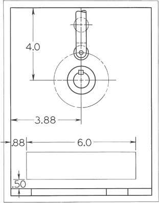
a. For the setup in the figure, draw the displacement diagram and determine the cam profile that will give the radial roller follower this motion: up 1.50″ in 120°, dwell 60°, down in 90°, dwell 90°. Motions are to be unmodified straight line and of uniform velocity. The roller is .75″ in diameter, and the base circle is 3.00″ in diameter. Note that the follower has zero offset. The cam rotates clockwise.
b. Instructions are the same as for part a, except that the straight-line motions are to be modified by arcs whose radii are equal to half the rise of the follower.
c. Instructions are the same as for part a, Except that the upward motion is to be harmonic and the downward motion parabolic.
d. Instructions are the same as for part c, except that the follower is offset 1.00″ to the left of the cam centerline. Full-size dimensions for suggested view placement are given in the example layout.
Exercise 16.11 For the 90° flat-faced follower in the figure, draw the displacement diagram, and determine the cam profile that will give the flat-faced follower this motion: dwell 30°, up 1.50″ on a parabolic curve in 180°, dwell 30°, down with harmonic motion in 120°. The base circle is 3.00″ in diameter. After completing the cam profile, determine the necessary width of face of the follower by finding the position of the follower where the point of contact with the cam is farthest from the follower axis. The cam rotates counterclockwise.
The minimum width of the follower face (2S) can be determined from
S = dy/d θ
where
θ = the angular displacement
y = the corresponding lift
The width of the follower face can also be determined by inspection of the widest tangent. See the figure.
Exercise 16.12 Draw the following for the 45° roller follower at right.
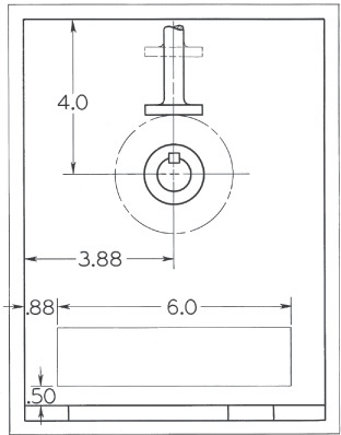
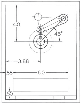
a. For the setup in the figure, draw the displacement diagram, and determine the cam profile that will swing the pivoted follower through an angle of 30° with the same motion as prescribed in Exercise 16.11. The radius of the follower arm is 2.75″, and in its lowest position the center of the roller is directly over the center of the cam. The base circle is 2.50″ in diameter, and the roller is .75″ in diameter. The cam rotates counterclockwise.
b. Follow instructions for part a, except that the motion is up 1.50″ in 120°, dwell 60°, down in 90°, dwell 90°.
c. Follow instructions for part a, except that the motion is to be dwell 30°, up 1.50″ on a parabolic curve in 180°, dwell 30°, down with harmonic motion in 120°.
Exercise 16.13 Draw the following by hand or using CAD, as given by your instructor.
a. Using an arrangement like 16.24, construct a half development and complete the front view for the following cylindrical cam. Cam, 2.50″ diameter, 2.50″ high. Roller, .50″ diameter; cam groove, .38″ deep. Camshaft, .62″ diameter; follower rod, .62″ wide, .31″ thick. Motion: up 1.50″ with harmonic motion in 180°, down with the same motion in remaining 180°. Cam rotates counterclockwise. Assume lowest position of the follower at the front center of cam.
b. Follow instructions for part a, but construct a full development for the following motion: up 1.5″ with parabolic motion in 120°, dwell 90°, down with harmonic motion in 150°.