After studying the material in this chapter, you should be able to:
1. Describe the various welding processes.
2. Draw the common welding symbols.
3. Dimension a welding drawing using standard ANSI welding notation.
4. Identify and draw a fillet weld, groove weld, back weld, spot weld, seam weld, projection weld, and flash weld.
5. Describe the use of welding symbols in CAD drawings.
Refer to the following standards:
• AWS A2.4 Standard Symbols for Welding, Brazing, and Nondestructive Examination
• AWS A1.1 Metric Practice Guide for the Welding Industry
• AWS A3.0 Standard Welding Terms and Definitions
An automobile frame is welded on a robotic automobile assembly line. (Courtesy of Vladimir Pcholkin/Stone/Getty Images.)
Overview
For fastening parts together permanently, rather than using bolts, screws, rivets, or other fasteners, welding is often the method of choice. Welding is widely used in fabricating machine parts or other structures that formerly would have been formed by casting or forging. Structural steel frames for buildings, ships, and other structures are often welded. Welding is one of few machine processes that adds material to a work-piece, rather than removing it.
Welding symbols on a mechanical drawing provide precise instructions for the welder. The weld type and the location of each weld must be clearly defined using standardized symbols. CAD libraries of welding symbols can simplify the drawing process. Welding templates can speed the process of drawing by hand.
Understanding Weldment Drawings
Welding is used extensively and for a wide variety of attachment purposes. A series of “Standard Welding Symbols” were developed in 1947 to provide an accurate method of showing the exact types, sizes, and locations of welds on construction drawings of machines or structures. Before these standards were developed, notes on the drawing such as “To be welded throughout” or “To be completely welded,” gave responsibility for welding control to the welding shop. Such instruction was dangerously vague and could be unnecessarily expensive, because shops would often “play it safe” by welding more than necessary.
Gas Welding The oxyacetylene method is generally known as gas welding. Gas welding originated in 1895, when the French chemist Le Châtelier discovered that the combustion of acetylene gas with oxygen produced a flame hot enough to melt metals. This discovery was soon followed by the development of practical methods to produce and transport oxygen and acetylene and the construction of torches and welding rods.
Arc Welding The electric arc method is generally known as arc welding. In arc welding, the heat of an electric arc is used to fuse the metals that are to be welded or cut. Gas metal arc welding (GMAW) is often known by its subtypes metal inert gas welding (MIG) and metal active gas welding (MAG).
Arc welding uses a wire electrode that is fed along with a shielding gas through the welding gun. Gas tungsten arc welding (GTAW), often known as tungsten inert gas welding (TIG), and plasma arc welding are processes that conduct the arc through a heated gas called a plasma to produce strong high-quality welds. Arc and gas welding are important construction processes in industry.
Resistance Welding Electric resistance welding is generally called resistance welding. In resistance welding, two pieces of metal are held together under some pressure, and a large amount of electric current is passed through the parts. The resistance of the metals to the passage of the current causes heat at the junction of the two pieces, resulting in the welding of the metals.
Standard Symbols
The text and illustrations of this chapter are based primarily on ANSI/AWS A2.4, Standard Symbols for Welding, Brazing, and Nondestructive Examination. You may also want to refer to AWS A1.1, Metric Practice Guide for the Welding Industry, and ANSI/AWS A3.0, Standard Welding Terms and Definitions.
Welding drawings are a special type of assembly drawing, as weldments are composed of a number of separate pieces fastened together as a unit. The welds themselves are not drawn but are clearly and completely indicated by the welding symbols. Figure 21.1 shows a drawing using standard welding symbols. Most CAD packages provide standard welding symbols that can quickly be inserted into your drawing.
21.1 (a) Portion of a Weldment Drawing and (b) Welded Structure (Photo has been rotated to the same orientation as the drawing in part a.) (Courtesy of Midwest Steel Industries.)
The joints are all shown in the drawing as they would appear before welding. Dimensions are given to show the sizes of the individual pieces to be cut from stock. Each component piece is identified by encircled numbers and by specifications in the parts list.
Understanding a Welding Symbol
A welding symbol added to the drawing has many different features that specify each detail of the weld. The items that can be specified are:
• Type of weld
• Process
• Depth of bevel, size, or strength for some weld types
• Groove weld size
• Finishing designator
• Contour
• Groove angle
• Root opening
• Length of weld
• Number and pitch (center to center spacing) of welds
• Whether the weld is to be field welded (done on site)
• All-around indicator
• Which side of the material is to be welded
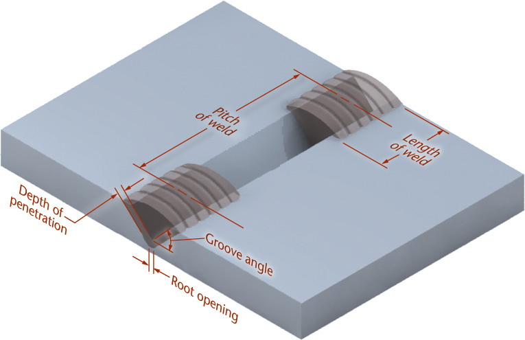
That is a lot of information contained in one symbol. The next sections provide more detail about the information contained in the symbol you will add to your drawings. Figure 21.1 shows an example of weld symbols used on a drawing and the actual welded part. Figure 21.2 points out features of a weld to which the symbol may refer.
21.2 Features of a Weld
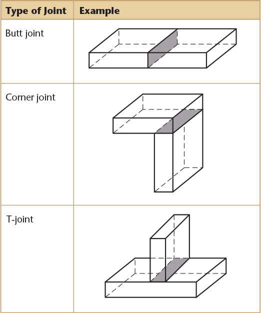
21.1 Types of Welded Joints
There are five basic types of welded joints: butt joint, corner joint, T-joint, lap joint, and edge joint. They are classified according to the positions of the parts being joined. Table 21.1 shows illustrations of the types of welded joints.
Table 21.1 Basic Types of Welded Joints
A number of different types of welds are applicable to each type of joint, depending on the thickness of metal, the strength of joint required, and other considerations.
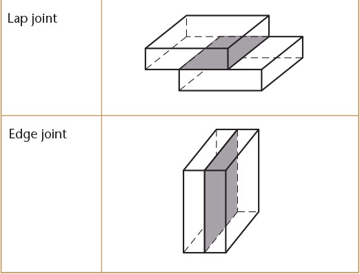
21.2 Types of Welds
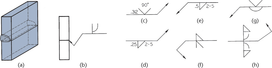
The four types of arc and gas welds are shown in Figure 21.3:
Groove welds are further classified as square, V, bevel, U, and J, as shown in Figures 21.3d through h.
More than one type of weld may be applied to a single joint. For example, a V weld may be on one side and a back weld on the other side. Frequently, the same type of weld is used on opposite sides, forming such welds as a double-V, a double-U, or a double-J.
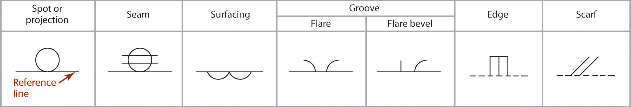
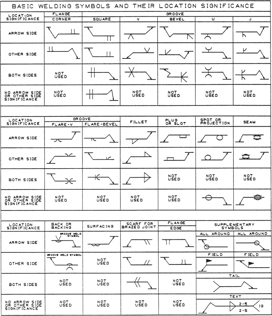
Except for the flash or upset weld, the corresponding symbols for these welds and additional basic weld symbols for surfacing, groove, and flange joints are given in Figure 21.4. (See Section 21.12 for the use of the square groove weld symbol for the flash or upset resistance weld.) Supplementary symbols are shown in Figure 21.5. Depending on your field and the particular project, you may need to use only a simple symbol composed of the minimum elements (the arrow and the weld symbol) or you may need to use the additional components.
21.4 Additional Basic Weld Symbols
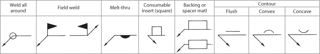
21.5 Supplementary Symbols
21.3 Welding Symbols
The basic element of the symbol is the “bent” arrow, as shown in Figure 21.6a. The arrow points to the joint where the weld is to be made (Figure 21.6b). Attached to the reference line, or shank, of the arrow is the weld symbol for the desired weld. The symbol would be one of those illustrated in Figures 21.3 and 21.4. In this case, a fillet weld symbol has been used.
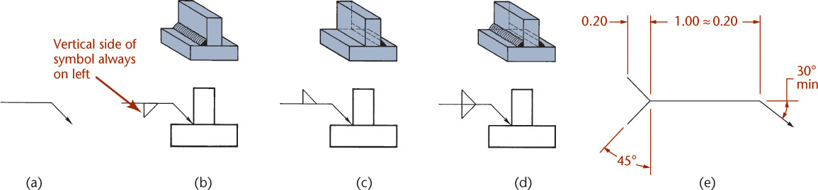
21.6 Welding Symbols
The weld symbol is placed below the reference line if the weld is to be on the arrow side of the joint, as in Figure 21.6b, or above the reference line if the weld is to be on the other side of the joint, as in Figure 21.6c. If the weld is to be on both the arrow side and the other side of the joint, weld symbols are placed on both sides of the reference line (Figure 21.6d). This rule for placement of the weld symbol is followed for all arc or gas weld symbols. Dimensions for creating a weld symbol are shown in Figure 21.6e.
When a joint is represented by a single line on a drawing, as in the top and side views of Figure 21.7b, the arrow side of the joint is regarded as the “near” side to the reader of the drawing, according to the usual conventions of technical drawing.
21.7 Arrow Side and Other Side
For the plug, slot, seam, and projection welding symbols, the arrow points to the outer surface of one of the members at the centerline of the weld. In such cases, the arrow side of the joint is the one to which the arrow points, or the side “near” the reader (see Sections 21.8 and 21.12).
Note that for all fillet or groove symbols, the vertical side of the symbol is always drawn on the left, as shown in Figure 21.6b.
For best results, welding symbols should be drawn using CAD or a template, but in certain cases where necessary, they may be drawn freehand.
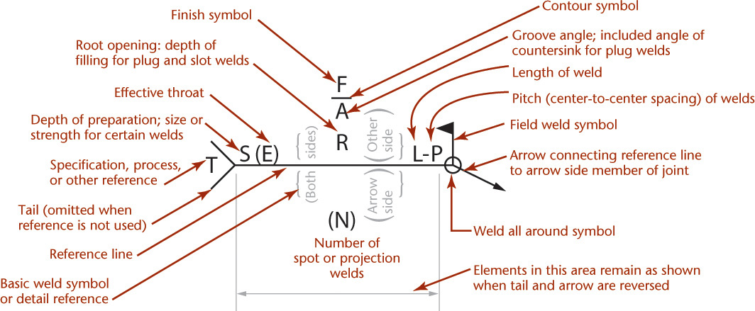
The complete welding symbol, enlarged, is shown in Figure 21.8. See Appendix 31 for additional welding symbol details.
21.8 The Standard Locations for the Elements of the Welding Symbol
Reference to a specification, process, or other supplementary information is indicated by a symbol in the tail of the arrow (Figure 21.9a). Otherwise, a general note may be placed on the drawing, such as
21.9 The Standard Locations for the Elements of the Welding Symbol
UNLESS OTHERWISE INDICATED, MAKE ALL WELDS PER SPECIFICATION NO. XXX
If no reference is indicated in the symbol, the tail may be omitted.
To avoid repeating the same information on many welding symbols on a drawing, general notes may be used, such as
FILLET WELDS .3125″ UNLESS OTHERWISE INDICATED
or
ROOT OPENINGS FOR ALL GROOVE WELDS .1875″ UNLESS OTHERWISE INDICATED
Welds extending completely around a joint are indicated by an open circle around the elbow of the arrow (Figure 21.9b). When the weld all around symbol is not used, the welding symbol is understood to apply between abrupt changes in direction of the weld, unless otherwise shown. A short vertical staff with a solid triangular flag at the elbow of the arrow indicates a weld to be made “in the field” (on the site) rather than in the fabrication shop (Figure 21.9c).
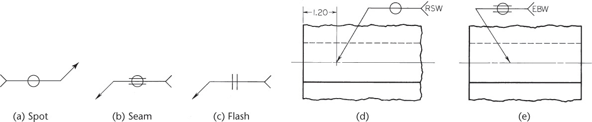
Spot, seam, flash, or upset symbols usually do not have arrow-side or other-side significance and are simply centered on the reference line of the arrow (Figures 21.10a through c). Spot and seam symbols are shown on the drawing as indicated in Figures 21.10d and e. Note that the required process must be specified in the tail of the symbol (RSW = resistance spot weld, EBW = electron beam weld).
21.10 Spot, Seam, and Flash Welding Symbols
For bevel or J-groove welds, the arrow should point with a definite change of direction, or break, toward the member that is to be beveled or grooved (Figures 21.11a and b). In this case, the upper member is grooved. The break is omitted if the location of the bevel or groove is obvious.
21.11 Welding Symbols
Lettering for the symbols should be placed to read from the bottom or from the right side of the drawing in accordance with the aligned system (Figures 21.11c through e). Dimensions may be indicated on a drawing in the fractional, decimal-inch, or metric system.
When a joint has more than one weld, the combined symbols are used (Figures 21.11f through h).
21.4 Fillet Welds
The usual fillet weld has equal legs (Figure 21.12a). The size of the weld is the length of one leg, as indicated by a dimension figure (fraction, decimal-inch, or metric) at the left of the weld symbol (Figure 21.12b). For fillet welds on both sides of a joint, the dimensions should be indicated on both sides of the reference line, whether the dimensions are identical or different. (Figure 21.12c). The lengths of the welds and the pitch (center-to-center spacing of welds) are indicated as shown. When the welds on opposite sides are different in size, the sizes are given as shown in Figure 21.12d. If a fillet weld has unequal legs, the weld orientation is shown on the drawing, if necessary, and the lengths of the legs are given in parentheses to the left of the weld symbol, as in Figure 21.12e. If a general note is given on the drawing, such as
ALL FILLET WELDS .3125″ UNLESS OTHERWISE NOTED
21.12 Dimensioning of Fillet Welds
the size dimensions are omitted from the symbols.
No length dimension is needed for a weld that extends the full distance between abrupt changes of direction. For each abrupt change in direction, an additional arrow is added to the symbol, except when the weld all around symbol is used.
Fillet Weld Length
Lengths of fillet welds may be indicated by symbols in conjunction with dimension lines (Figure 21.13a). The extent of fillet welding may be shown graphically with section lining if desired (Figure 21.13b).
21.13 Lengths of Fillet Welds
Intermittent Fillet Welding
Chain intermittent fillet welding is indicated as shown in Figure 21.14a. If the welds are staggered, the weld symbols are staggered (Figure 21.14b).
21.14 Intermittent Welds
Surface Contour and Fillet Welds
Unfinished flat-faced fillet welds are indicated by adding the flush symbol (see Figure 21.5), to the weld symbol (Figure 21.15a). If fillet welds are to be made flat-faced by mechanical means, add the flush-contour symbol and the user’s standard finish symbol to the weld symbol (Figures 21.15b through d). These finish symbols indicate the method of finishing (C = chipping, G = grinding, M = machining, R = rolling, H = hammering) and not the degree of finish. If fillet welds are to be finished to a convex contour, the convex-contour symbol is added, together with the finish symbol (Figure 21.15e).
21.15 Surface Contour of Fillet Welds
21.5 Groove Welds
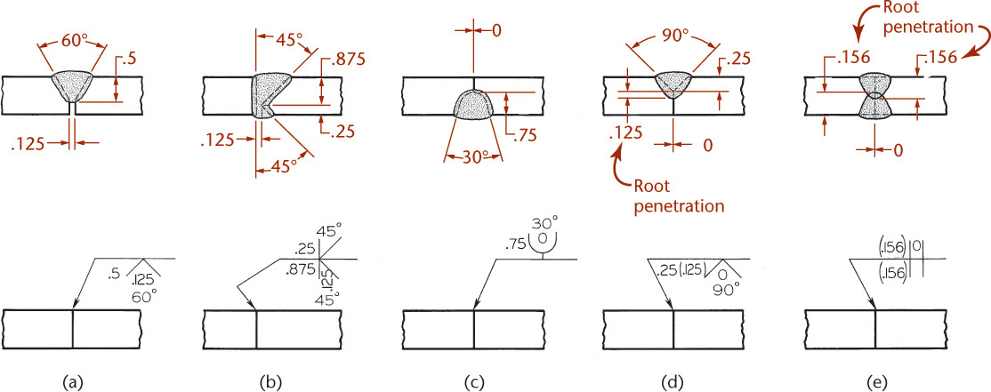
In Figure 21.16, various groove welds are shown in the top row with their corresponding symbolic representations shown below. The sizes of the groove welds (depth of the V, bevel, U, or J) are indicated on the left of the weld symbol. For example, in Figure 21.16a, the size of the V-weld is .50″, in Figure 21.16b the sizes are .25″ and .875″, in Figure 21.16c the size is .75″, and in Figure 25.16d the size is .25″. For the symbol in Figure 21.16d the size is followed by .125″, which is the additional “root penetration” of the weld. In Figure 21.16e, the root penetration is .156″ from zero, or from the outside of the members. Note the overlap of the root penetration in this case.
21.16 Groove Welds
The root opening or space between members, when not covered by a company standard, is shown within the weld symbol. In Figures 21.16a and b, the root openings are .125″. In Figures 21.16c through e, the openings are zero.
The groove angles, when not covered by a company standard, appear just outside the openings of the weld symbols (Figures 21.16a and b).
A general note may be used on the drawing to avoid repeating the symbols, such as
ALL V-GROOVE WELDS TO HAVE 60° GROOVE ANGLE UNLESS OTHERWISE SHOWN
However, when the dimensions of one or both of two opposite welds differ from the general note, both welds should be completely dimensioned.
When single-groove or symmetrical double-groove welds extend completely through, the size need not be added to the welding symbol. For example, in Figure 21.16a, if the V-groove extended entirely through the joint, the depth or size would simply be the thickness of the stock and would not need to be indicated in the welding symbol.
Surface Contour and Groove Welds
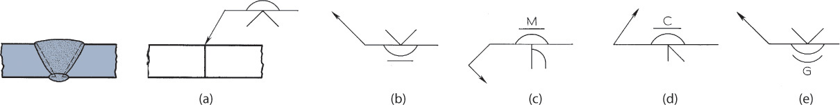
When groove welds are to be approximately flush without finishing, add the flush-contour symbol (see Figure 21.5) to the weld symbols (Figures 21.17a and b). If the welds are to be machined, add the flush-contour symbol and the user’s standard finish symbol to the weld symbol (Figures 21.17c and d). These finish symbols indicate the method of finishing (C= chipping, G = grinding, M = machining) and not the degree of finish. If a groove weld is to be finished with a convex-contour, add the convex-contour and finish symbols, as in Figure 21.17e.
21.17 Surface Contour of Groove Welds
21.6 Back or Backing Welds
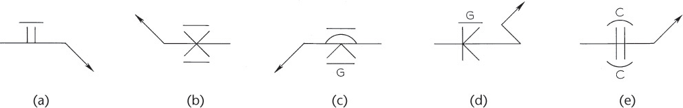
A back or backing symbol opposite the groove weld symbol indicates bead-type welds used as back or backing welds on single-groove welds (Figure 21.18a). Dimensions for back or backing welds are not shown on the symbol, but may be shown, if necessary, directly on the drawing.
21.18 Back or Backing Weld Symbols
A flush contour symbol included in the weld symbols indicates that the back or backing welds are to be approximately flush without machining (Figure 21.18b). If they are to be machined, the user’s finish symbol is added (Figures 21.18c and d). If the welds are to be finished with a convex contour, the convex-contour symbol and the finish symbol are included in the weld symbol, as shown in Figure 21.18e.
21.7 Surface Welds
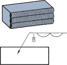
The surface weld symbol indicates a surface to be built up with single- or multiple-pass bead type welds (Figure 21.19). Because this symbol does not indicate a welded joint, there is no arrow-side or other-side significance, so the symbol is always drawn below the reference line. Indicate the minimum height of the weld deposit at the left of the weld symbol, except where no specific height is required. When a specific area of a surface is to be built up, give the dimensions of the area on the drawing.
21.19 Surface Weld Symbol
21.8 Plug and Slot Welds
The same symbol is used for plug welds and slot welds. Figures 21.20a and d show the hole or slot that is made to receive the weld. If it is in the arrow-side member, place the weld symbol below the reference line, as shown Figures 21.20b and c. If it is in the other-side member, place the weld symbol above the line, as shown in Figures 21.20e and f.
21.20 Plug and Slot Welds
Place the size of a plug weld (which is the smallest diameter of the hole, if countersunk) at the left of the weld symbol. If the included angle for the countersink of a plug weld is in accordance with the user’s standard, omit it; otherwise, place it adjacent to the weld symbol as shown in Figures 21.20b and c.
A plug weld is understood to fill the depth of the hole unless its depth is indicated inside the weld symbol, as shown in Figure 21.21a. The pitch of plug welds is shown at the right of the weld symbol (Figure 21.21b). If the weld is to be approximately flush without finishing, add the flush-contour symbol, as in Figure 21.21c. If the weld is to be made flush by mechanical means, a finish symbol is added (Figure 21.21d). Flush-contour and finish symbols are used the same way for slot welds and for plug welds.
21.21 Plug Welds
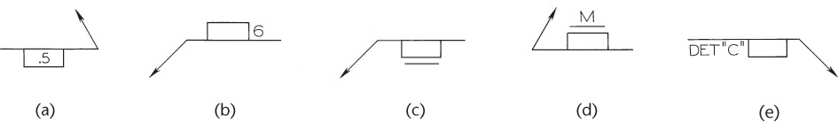
Indicate the depth of filling for slot welds the same way as for plug welds (Figure 21.21a). The size and location dimensions of slot welds cannot be shown on the welding symbol. Show them directly on the drawing (Figure 21.20f) or in a detail with a reference to it on the welding symbol, as shown in Figure 21.21e.
21.9 Spot Welds
The spot weld symbol, with the required welding process indicated in the tail, may or may not have arrow-side or other-side significance. Show dimensions on the same side of the reference line as the symbol, or on either side when the symbol is centered on the reference line and no arrow-side or other-side significance is intended.
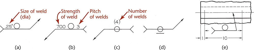
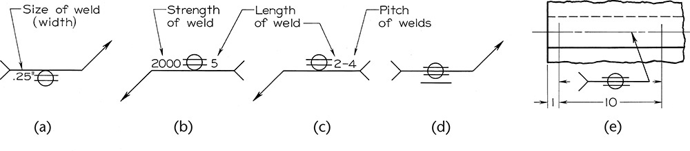
The size of a spot weld is its diameter. Show this value at the left of the weld symbol on either side of the reference line (Figure 21.22a). If you need to indicate the minimum acceptable shear strength in pounds per spot, instead of the size of the weld, place this value at the left of the weld symbol, and indicate pitch at the right of the weld symbol, as shown in Figure 21.22b. In this case the spot welds are 3″ apart.
21.22 Spot Welds
If a joint requires a certain number of spot welds, give the number in parentheses above or below the symbol, as in Figure 21.22c. If the exposed surface of one member is to be flush, add the flush-contour symbol above the symbol if it is the other-side member, and below it if it is the arrow-side member, as in Figure 21.22d. Figure 21.22e shows the welding symbol used in conjunction with ordinary dimensions.
21.10 Seam Welds
The seam weld symbol, with the welding process indicated in the tail, may or may not have arrow-side or other-side significance. Dimensions are shown on the same side of the reference line as the symbol, or on either side when the symbol is centered on the reference line and no arrow-side or other-side significance is intended.
The size of the seam weld is its width. Show this value at the left of the weld symbol, on either side of the reference line (Figure 21.23a). If you need to indicate the minimum acceptable shear strength in pounds per linear inch, instead of the size of the weld, place this value at the left of the weld symbol, and show the length of a seam weld at the right of the weld symbol, as in Figure 21.23b. In this case, the seam weld is 5″ long. If the weld extends the full distance between abrupt changes of direction, no length dimension in the symbol is given.
21.23 Seam Welds
The pitch of intermittent seam welding is the distance between centers of lengths of welding. Show the pitch at the right of the length value (Figure 21.23c). In this case, the welds are 2″ long and spaced 4″ center to center.
When the exposed surface of one member is to be flush, add the flush-contour symbol above the symbol if it is the other-side member and below it if it is the arrow-side member (Figure 21.23d). Figure 21.23e shows the welding symbol used in conjunction with ordinary dimensions.
21.11 Projection Welds
In projection welding, one member is embossed in preparation for the weld (Figure 21.24a). When welded, the joint appears in section, as in Figure 21.24b. In this case, the weld symbols are placed below the reference lines (Figure 21.24c) to indicate that the arrow-side member is the one that is embossed. The weld symbols would be placed above the lines if the other member were embossed.
21.24 Projection Welds
Projection welds are dimensioned by either size or strength. The size is the diameter of the weld. This value is shown to the left of the weld symbol (Figure 21.24d). If you need to indicate the minimum acceptable shear strength in pounds per weld, place the value at the left of the weld symbol (Figure 21.24e). Indicate the pitch at the right of the weld symbol (Figure 21.24e). In this case, the welds are spaced 6″ (152 mm) apart. If the joint requires a definite number of welds, give the number in parentheses (Figure 21.24e). If the exposed surface of one member is to be flush, add the flush-contour symbol (Figure 21.24f). Figure 21.24g shows the welding symbol used in conjunction with ordinary dimensions. The welding process reference is required in the tail of the symbol.
21.12 Flash and Upset Welds
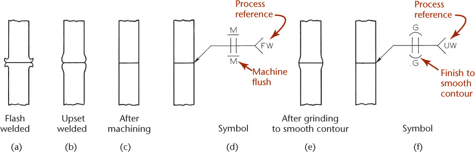
Flash and upset weld symbols have no arrow-side or other-side significance, but the supplementary symbols do. A flash-welded joint is shown in Figure 21.25a, and an upset-welded joint in Figure 21.25b. The joint after machining flush is shown in Figure 21.25c. The complete symbol (Figure 21.25d) includes the weld symbol together with the flush-contour and machining symbols.
21.25 Flash and Upset Welds
If the joint is ground to smooth contours (Figure 21.25e), the resulting welding drawing and symbol would be constructed as in Figure 21.25f, which includes convex-contour and grind symbols. In either Figure 21.25d or f, the joint may be finished on only one side, if desired, by indicating the contour and machining symbols on the appropriate side of the reference line. The dimensions of flash and upset welds are not shown on the welding symbol. Note that the process reference for flash welding (FW) or upset welding (UW) must be placed in the tail of the symbol.
21.13 Welding Applications
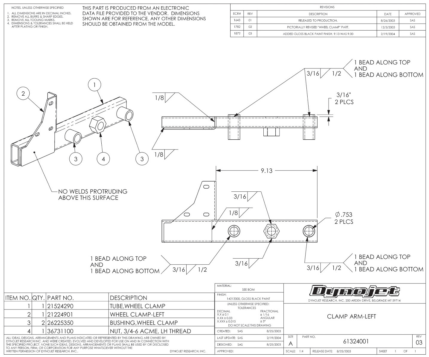
A typical example of welding fabrication for machine parts is shown in Figure 21.26. In many cases, especially when only one or a few identical parts are required, it is cheaper to produce by welding than to make patterns and sand castings and do the necessary machining. Thus, welding is particularly adaptable to custom-built constructions.
21.26 Application of Welding-Fabrication for Machine Parts (Courtesy of Dynojet Research, Inc.)
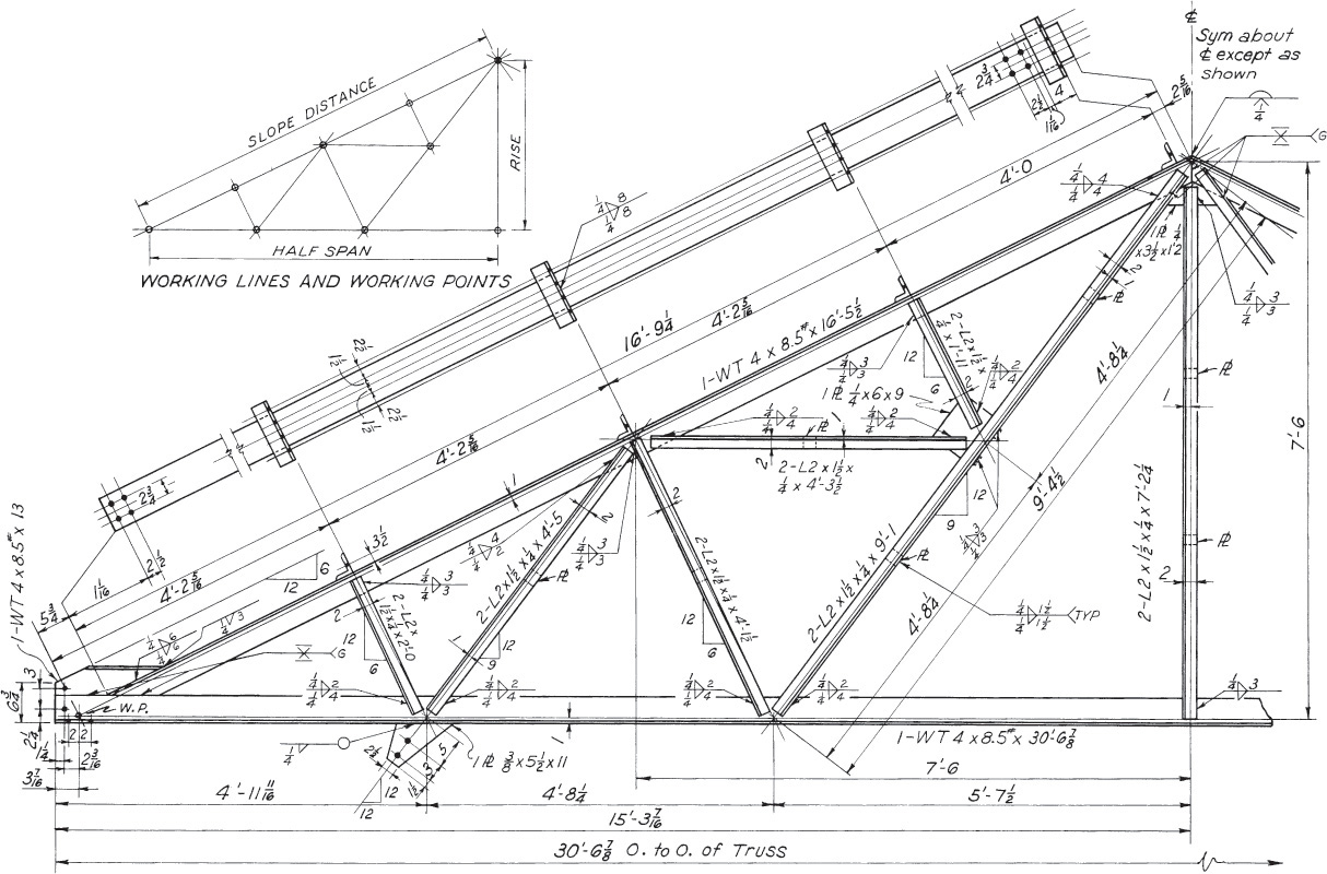
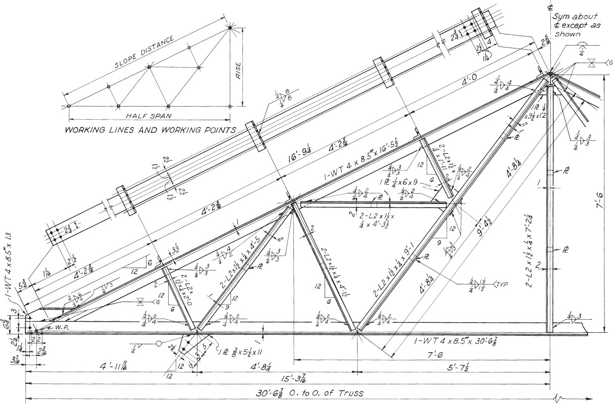
Welding is also suitable for large structures that are difficult or impossible to fabricate entirely in the shop, and it is coming into greater use for steel structures, such as building frames, bridges, and ships. A welded beam is shown in Figure 18.16, and a welded assembly of diagonal bracing between two columns is shown in Figure 18.17. A welded truss is shown in Figure 21.27. It is easier to place members in such a welded truss so that their center-of-gravity axes coincide with the working lines of the truss than is the case in a riveted truss. Compare this welded truss with the riveted truss in Figure 18.14.
21.27 A Welded Truss
21.14 Welding Templates
Welding templates can simplify drawing welding symbols by hand (which may be done in pencil or ink). They have all the forms needed for drawing the arrow, weld symbols, and supplementary symbols, as well as an illustration of the complete composite welding symbol for quick reference.
21.15 Computer Graphics
Welding symbols libraries available in CAD (Figure 21.29) allow for rapid application of accurate, uniform symbols that are in compliance with AWS standards (Figure 21.28). In addition to standard symbols, many CAD programs permit the operator to create custom symbols as required.
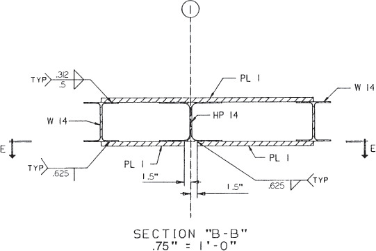
21.28 CAD-Generated Welded Structural Detail
21.29 Computervision Production Drafting Symbols
CADatWork:Weld Symbols from CAD
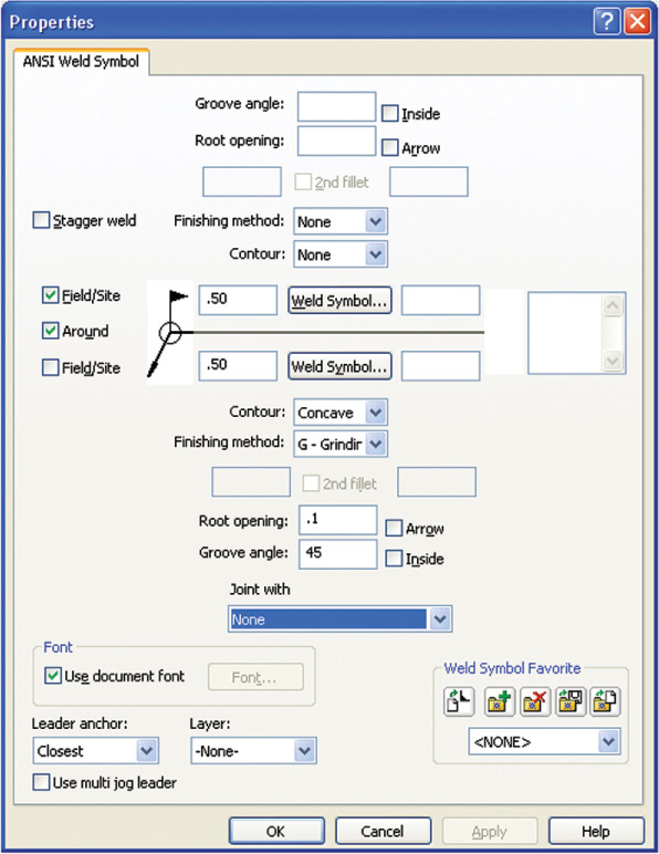
Most CAD systems provide a way to quickly generate weld symbols to place in your drawing. The SolidWorks dialog box shown in Figure A allows you to select the symbol for type and size of weld, field placement, whether to add the all-around symbol, and special indications for contour and finish method. Once you have made your selections, the weld symbol as shown in Figure B is automatically generated from them, and you have only to click to place the symbol in your drawing.
(A) SolidWorks Weld Symbol Dialog Box (Courtesy of SolidWorks Corporation.)
(B) Automatically Generated Weld Symbol (Courtesy of SolidWorks Corporation.)
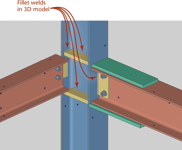
Specialized software such as Design Data’s SDS/2 allows you to design and model connections between members based on parameters that you define for each job. You can designate the material, edge distance, cope criteria, and other connection specifications, and SDS/2 will automatically generate connections. You can model all the details, for example, the fillet welds shown in Figure C, using the software’s 3D modeler. 2D drawings can be taken directly from the model, providing an accurate fit in the field.
(C) Fillet Welds in a 3D Model (Courtesy of Paul Hergett, Midwest Steel Industries.)
Portfolio
Welding symbols specify the welds for attaching the tube, bushings, nut, and plate for the clamp arm. (Courtesy of Dynojet Research, Inc.)
Welding symbols specify how plates attach to a structural beam in this drawing created from a 3D model using SDS/2 software. (Courtesy of Paul Hergett, Midwest Steel Industries.)
Exercise 21.22 Make a half-size drawing of the joint at the center of the lower chord of the truss where the chord is supported by two vertical angles. The chord is a structural tee, cut from an, 8″ × 5–1/4″, 17 lb, wide flange shape. Draw the front and side views, and show the working lines, the two angles, the structural tee, and all welding symbols.
Exercise 21.23 Make a half-size front view, showing the welding symbols, of any joint of the roof truss in which three or four members meet.
Exercise 21.24 Draw half-size front, top, and left-side views of the end joint of the truss in showing the welding symbols.