
Chapter Twenty-Two. Axonometric Projection
Objectives
After studying the material in this chapter, you should be able to:
1. Sketch examples of an isometric cube, a dimetric cube, and a trimetric cube.
2. Create an isometric drawing given a multiview drawing.
3. Use the isometric axes to locate drawing points.
4. Draw inclined and oblique surfaces in isometric.
5. Use projection to create an axonometric drawing.
6. Use offset measurements to show complex shapes in oblique drawings.
7. Add dimensions to oblique drawings.
8. Explain why CAD software does not automatically create oblique drawings.
Refer to the following standard:
• ASME Y14.4M Pictorial Drawing
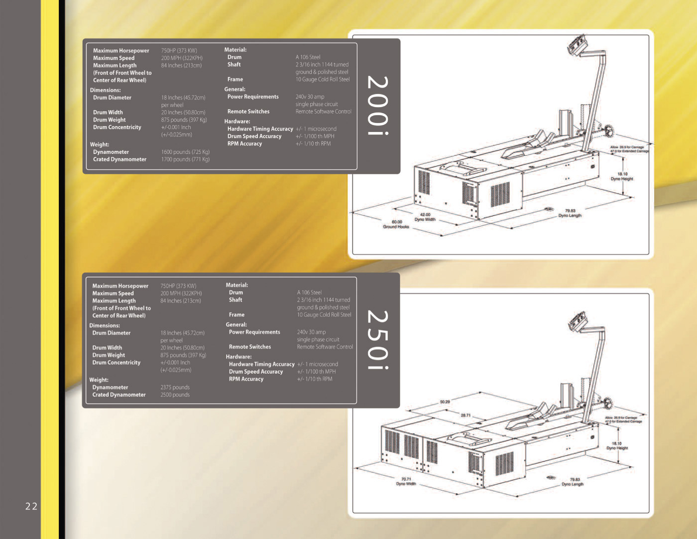
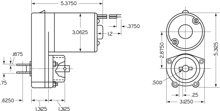
A Portion of a Sales Brochure Showing General Dimensions in Pictorial Drawings (Courtesy of Dynojet Research, Inc.)
Understanding Axonometric Projection
Projection Methods Reviewed
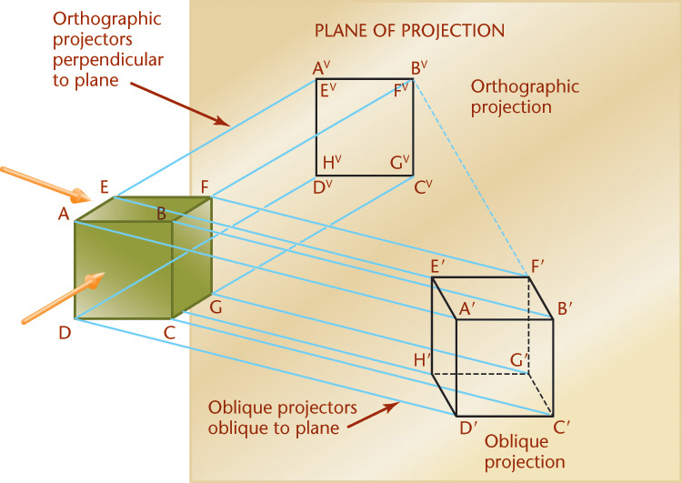
The four principal types of projection are illustrated in Figure 22.1. All except the regular multiview projection (Figure 22.1a) are pictorial types because they show several sides of the object in a single view. In both multiview projection and axonometric projection (Figure 22.1b), the visual rays are parallel to each other and perpendicular to the plane of projection. Both are types of orthographic projections.
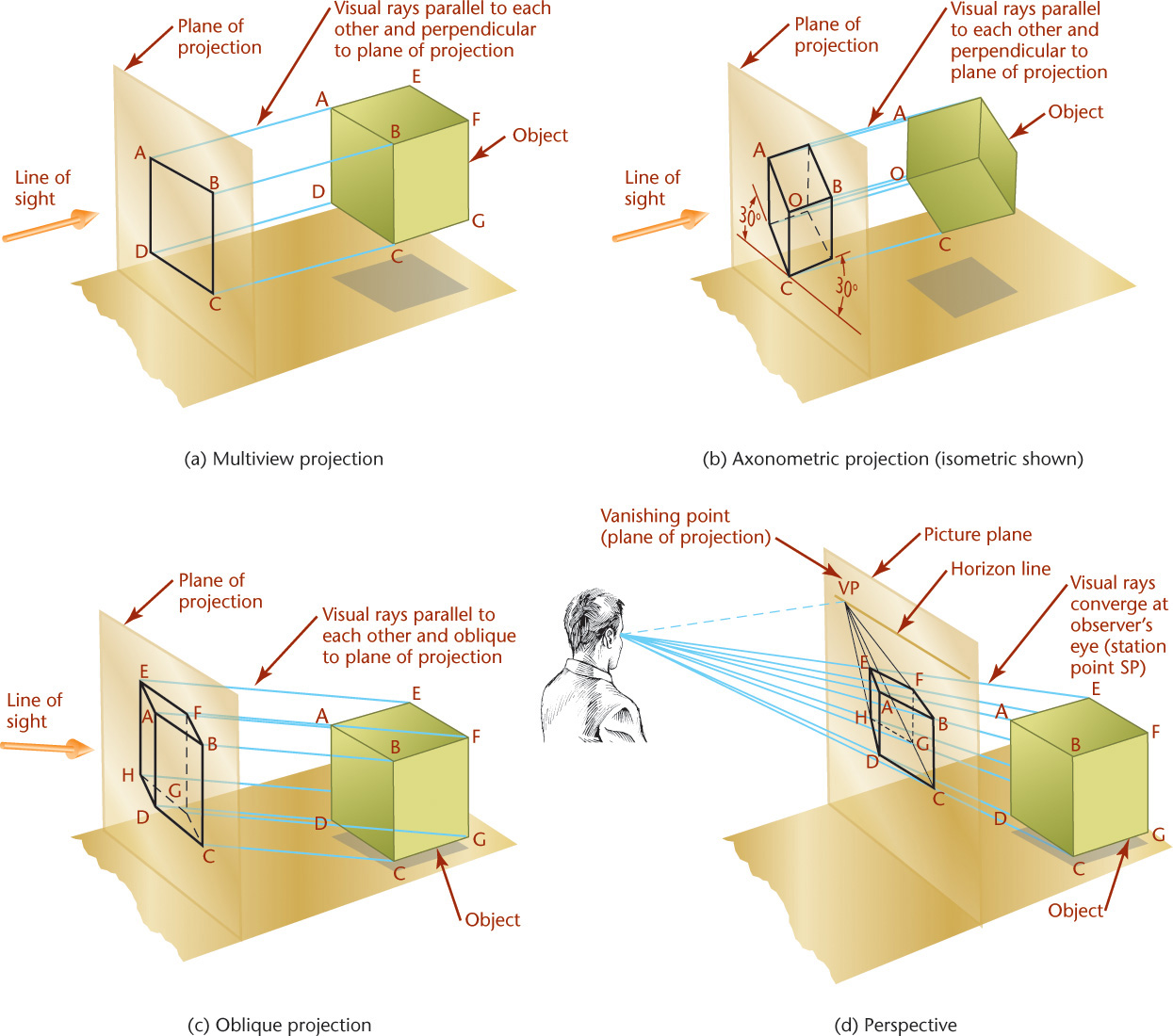
In oblique projection (Figure 22.1c), the visual rays are parallel to each other but at an angle other than 90° to the plane of projection.
In perspective (Figure 22.1d), the visual rays extend from the observer’s eye, or station point (SP), to all points of the object to form a “cone of rays” so that the portions of the object that are farther away from the observer appear smaller than the closer portions of the object.
Review Chapter 3 for details on how to create basic pictorial sketches.
Types of Axonometric Projection
The feature that distinguishes axonometric projection from multiview projection is the inclined position of the object with respect to the planes of projection. When a surface or edge of the object is not parallel to the plane of projection, it appears foreshortened. When an angle is not parallel to the plane of projection, it appears either smaller or larger than the true angle.
To create an axonometric view, the object is tipped to the planes of projection so that all of the principal faces show in a single view. This produces a pictorial drawing that is easy to visualize. But, because the principal edges and surfaces of the object are inclined to the plane of projection, the lengths of the lines are foreshortened. The angles between surfaces and edges appear either larger or smaller than the true angle. There are an infinite variety of ways that the object may be oriented with respect to the plane of projection.
The degree of foreshortening of any line depends on its angle to the plane of projection. The greater the angle, the greater the foreshortening. If the degree of foreshortening is determined for each of the three edges of the cube that meet at one corner, scales can be constructed for measuring along these edges or any other edges parallel to them (Figure 22.2).

Use the three edges of the cube that meet at the corner nearest your view as the axonometric axes. In Figure 22.1b, the axonometric axes, or simply the axes, are OA, OB, and OC. Figure 22.3 shows three axonometric projections with axes OX, OY, and OZ.
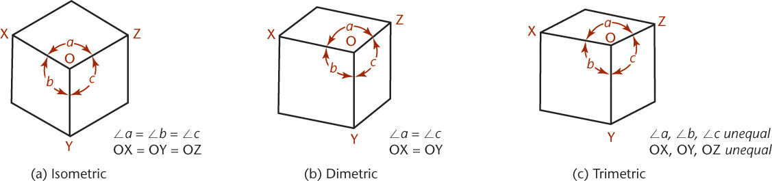
Isometric projection (Figure 22.3a) has equal foreshortening along each of the three axis directions.
Dimetric projection (Figure 22.3b) has equal foreshortening along two axis directions and a different amount of foreshortening along the third axis. This is because the third axis is not tipped an equal amount to the principal plane of projection.
Trimetric projection (Figure 22.3c) has different foreshortening along all three axis directions. This view is produced by an object whose axes are not equally tipped to the plane of projection.
22.1 Dimetric Projection
A dimetric projection is an axonometric projection of an object in which two of its axes make equal angles with the plane of projection, and the third axis makes either a smaller or a greater angle (Figure 22.4). The two axes making equal angles with the plane of projection are foreshortened equally; the third axis is foreshortened in a different proportion.
Usually, the object is oriented so one axis is vertical. However, you can revolve the projection to any orientation if you want that particular view.
Do not confuse the angles between the axes in the drawing with the angles from the plane projection. These are two different but related things. You can arrange the amount that the principal faces are tilted to the plane of projection in any way as long as the two angles between the axes are equal and over 90°.
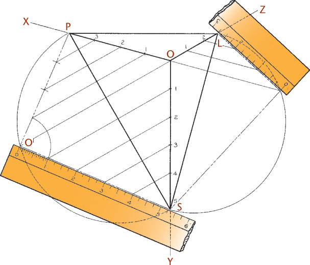
The scales can be determined graphically, as shown in Figure 22.5a, in which OP, OL, and OS are the projections of the axes or converging edges of a cube. If the triangle POS is revolved about the axis line PS into the plane of projection, it will show its true size and shape as PO′S. If regular full-size scales are marked along the lines O′P and O′S, and the triangle is counterrevolved to its original position, the dimetric scales may be divided along the axes OP and OS, as shown.

You can use an architect’s scale to make the measurements by assuming the scales and calculating the positions of the axes, as follows:
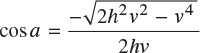
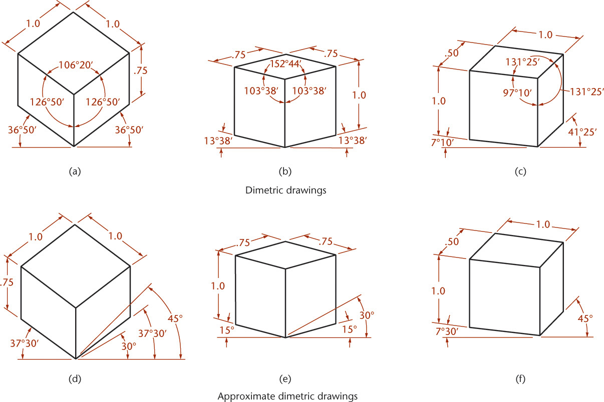
where a is one of the two equal angles between the projections of the axes, h is one of the two equal scales, and v is the third scale. Examples are shown in the upper row of Figure 22.4, where length measurements could be made using an architect’s scale. One of these three positions of the axes will be found suitable for almost any practical drawing.
22.2 Approximate Dimetric Drawings
Approximate dimetric drawings, which closely resemble true dimetrics, can be constructed by substituting for the true angles shown in the upper half of Figure 22.4 angles that can be obtained with the ordinary triangles and compass, as shown in the lower half of the figure. The resulting drawings will be accurate enough for all practical purposes.
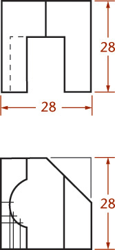
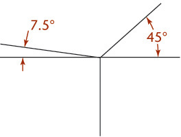
![]() To make a dimetric drawing for the views given, draw two intersecting axis lines at angles of 7.5° and 45° from horizontal. Draw the third axis vertically through them.
To make a dimetric drawing for the views given, draw two intersecting axis lines at angles of 7.5° and 45° from horizontal. Draw the third axis vertically through them.
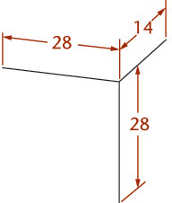
![]() The dimensions for the principal face are measured full size. The dimension for the receding axis direction will be at half scale.
The dimensions for the principal face are measured full size. The dimension for the receding axis direction will be at half scale.

![]() Block in the features relative to the surfaces of the enclosing box. The offset method of drawing a curve is shown in the figure.
Block in the features relative to the surfaces of the enclosing box. The offset method of drawing a curve is shown in the figure.

An Approximate Dimetric Drawing
Follow these steps to make a dimetric sketch with the position similar to that in Figure 22.4e where the two angles are equal.

![]() Using whichever angle produces a good drawing of your part, block in the dimetric axes. An angle of 20° from horizontal tends to show many parts well.
Using whichever angle produces a good drawing of your part, block in the dimetric axes. An angle of 20° from horizontal tends to show many parts well.
![]() Block in the major features, foreshortening the dimensions along the two receding axes to approximately 75%.
Block in the major features, foreshortening the dimensions along the two receding axes to approximately 75%.

![]() Darken the final lines.
Darken the final lines.
22.3 Trimetric Projection
A trimetric projection is an axonometric projection of an object oriented so that no two axes make equal angles with the plane of projection. In other words, each of the three axes, and the lines parallel to them, have different ratios of foreshortening. If the three axes are selected in any position on paper so that none of the angles is less than 90°, and they are not an isometric nor a dimetric projection, the result will be a trimetric projection.
22.4 Trimetric Scales
Because the three axes are foreshortened differently, each axis will use measurement proportions different from the other two. You can select which scale to use, as shown in Figure 22.6. Any two of the three triangular faces can be revolved into the plane of projection to show the true lengths of the three axes. In the revolved position, the regular scale is used to set off inches or fractions thereof. When the axes have been counterrevolved to their original positions, the scales will be correctly foreshortened, as shown.
Tip
You can make scales from thin card stock and transfer these dimensions to each card for easy reference. You might even want to make a trimetric angle from Bristol Board or plastic, as shown here, or six or seven of them, using angles for a variety of positions of the axes.
22.5 Trimetric Ellipses
The trimetric centerlines of a hole, or the end of a cylinder, become the conjugate diameters of an ellipse when drawn in trimetric. The ellipse may be drawn on the conjugate diameters or you can determine the major and minor axes from the conjugate diameters and construct the ellipse on them with an ellipse template or by any of the methods shown in Chapter 3.
One advantage of trimetric projection is the infinite number of positions of the object available. The angles and scales can be handled without too much difficulty, as shown in Section 22.4. However, in drawing any axonometric ellipse, keep the following in mind:
1. On the drawing, the major axis is always perpendicular to the centerline, or axis, of the cylinder.
2. The minor axis is always perpendicular to the major axis; on the paper it coincides with the axis of the cylinder.
3. The length of the major axis is equal to the actual diameter of the cylinder.
The directions of both the major and minor axes, and the length of the major axis, will always be known, but not the length of the minor axis. Once it is determined, you can construct the ellipse using a template or any of a number of ellipse constructions. For sketching you can generally sketch an ellipse that looks correct by eye.
In Figure 22.7a, locate center O as desired, and draw the horizontal and vertical construction lines that will contain the major and minor axes through O. Note that the major axis will be on the horizontal line perpendicular to the axis of the hole, and the minor axis will be perpendicular to it, or vertical.

Use the actual radius of the hole and draw the semicircle, as shown, to establish the ends A and B of the major axis. Draw AF and BF parallel to the axonometric edges WX and YX, respectively, to locate F, which lies on the ellipse. Draw a vertical line through F to intersect the semicircle at F′ and join F′ to B, as shown. From D′, where the minor axis, extended, intersects the semicircle, draw D′E and ED parallel to F′B and BF, respectively. Point D is one end of the minor axis. From center O, strike arc DC to locate C, the other end of the minor axis. On these axes, a true ellipse can be constructed, or drawn with an ellipse template.
See Chapter 3 for additional methods for constructing ellipses.
In constructions where the enclosing parallelogram for an ellipse is available or easily constructed, the major and minor axes can be determined as shown in Figure 22.7b. The directions of both axes and the length of the major axis are known. Extend the axes to intersect the sides of the parallelogram at L and M, and join the points with a straight line. From one end N of the major axis, draw a line NP parallel to LM. The point P is one end of the minor axis. To find one end T of the minor axis of the smaller ellipse, it is necessary only to draw RT parallel to LM or NP.
The method of constructing an ellipse on an oblique plane in trimetric is similar to that shown in the Step by Step in Chapter 3 for drawing an isometric ellipse by offset measurements.
Tip
When you are creating a trimetric sketch of an ellipse, it works great to block in the trimetric rectangle that would enclose the ellipse and sketch the ellipse tangent to the midpoints of the rectangle.
Presentation Drawing
The MARGE (Mars Autonomous Rover for Geoscience Exploration) aeroshell, shown at right, is part of a NASA Scout mission proposal developed by Malin Space Science Systems and the Raytheon Company in 2005 and 2006. The blunt, conical MARGE aeroshell is an integrated system providing safe delivery of its payload, two small, autonomous rovers, to the surface of Mars. The aeroshell is about 2.4 m in diameter.
Shown here is the part of the system that provides aerobraking for the spacecraft’s initial descent from orbit, the terminal rocket descent phase just before landing, and the final soft touchdown with the surface. With the protective backshell (where the parachute is located) and rovers removed, you can clearly see the components of the propulsion and control systems integrated into the rover egress deck, color coded for clarity. In addition to aerobraking and rocket-powered descent, the MARGE aeroshell design incorporates crushable foam layers of increasing density to cushion the final touchdown with the planet surface. After the descent and landing phase is complete, clamps are disengaged, and the rovers drive off the lip of the aeroshell under their own power.
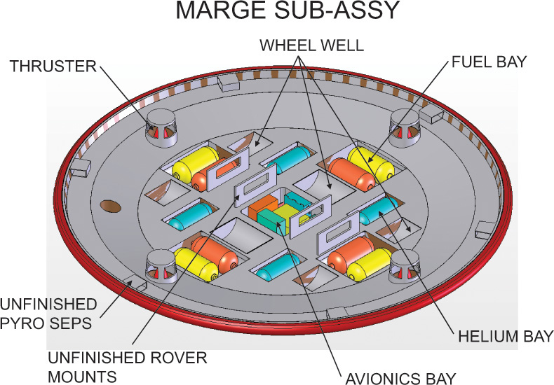
Shaded isometric views of 3D models are often used as presentation drawings. This isometric view of a proposed design for the MARGE aeroshell was used as a presentation drawing to communicate the features of a concept developed by Malin Aerospace. (Courtesy of Malin Space Science Systems, Inc.)
22.6 Axonometric Projection Using Intersections
Before the advent of CAD engineering, scholars devised methods to create an axonometric projection using projections from two orthographic views of the object. This method, called the method of intersections, was developed by Professors L. Eckhart and T. Schmid of the Vienna College of Engineering and was published in 1937.
To understand their method of axonometric projection, study Figure 22.8 as you read through the following steps. Assume that the axonometric projection of a rectangular object is given, and it is necessary to find the three orthographic projections: the top view, front view, and side view.

Place the object so that its principal edges coincide with the coordinate axes, and the plane of projection (the plane on which the axonometric projection is drawn) intersects the three coordinate planes in the triangle ABC.
From descriptive geometry, we know that lines BC, CA, and AB will be perpendicular, respectively, to axes OX, OY, and OZ. Any one of the three points A, B, or C may be assumed anywhere on one of the axes to draw triangle ABC.
To find the true size and shape of the top view, revolve the triangular portion of the horizontal plane AOC, which is in front of the plane of projection, about its base CA, into the plane of projection. In this case, the triangle is revolved inward to the plane of projection through the smallest angle made with it. The triangle would then be shown in its true size and shape, and you could draw the top view of the object in the triangle by projecting from the axonometric projection, as shown (because all width dimensions remain the same).
In the figure, the base CA of the triangle has been moved upward to C′A′ so that the revolved position of the triangle will not overlap its projection.
The true sizes and shapes of the front view and side view can be found similarly, as shown in the figure.
Note that if the three orthographic projections, or in most cases any two of them, are given in their relative positions, as shown in Figure 22.8, the directions of the projections could be reversed so that the intersections of the projecting lines would determine the axonometric projection needed.
Use of an Enclosing Box to Create an Isometric Sketch using Intersections
To draw an axonometric projection using intersections, it helps to make a sketch of the desired general appearance of the projection as shown in Figure 22.9. Even for complex objects the sketch need not be complete, just an enclosing box. Draw the projections of the coordinate axes OX, OY, and OZ parallel to the principal edges of the object, as shown in the sketch, and the three coordinate planes with the plane of projection.
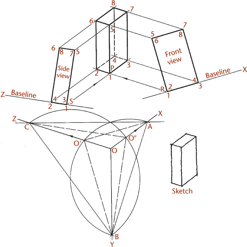
Revolve the triangle ABO about its base AB as the axis into the plane of projection. Line OA will revolve to O′A, and this line, or one parallel to it, must be used as the baseline of the front view of the object. Draw the projecting lines from the front view to the axonometric parallel to the projection of the unrevolved Z-axis, as indicated in the figure.
Similarly, revolve the triangle COB about its base CB as the axis into the plane of projection. Line CO will revolve to CO′. Use this line, or one parallel to it, as the baseline of the side view. Make the direction of the projecting lines parallel to the projection of the unrevolved X axis, as shown.
Draw the front view baseline at a convenient location parallel to O′A. Use the parallel line you drew (P3) as the base and draw the front view of the object. Draw the side view baseline at a convenient location parallel to O′C. Use it as the base (P2) for the side view of the object, as shown. From the corners of the front view, draw projecting lines parallel to OZ. From the corners of the side view, draw projecting lines parallel to OX. The intersections of these two sets of projecting lines determine the axonometric projection. It will be an isometric, a dimetric, or a trimetric projection, depending on the form of the sketch used as the basis for the projections.
If the angles formed by the three coordinate axes are equal, the projection is isometric; if two of them are equal, the projection is dimetric; and if none of the three angles are equal, the result is a trimetric projection.
To place the desired projection on a specific location on the drawing (Figure 22.9), select the desired projection P of point 1, for example, and draw two projecting lines PR and PS to intersect the two baselines and thereby to determine the locations of the two views on their baselines.
Another example of this method of axonometric projection is shown in Figure 22.10. In this case, it was necessary only to draw a sketch of the plan or base of the object in the desired position.
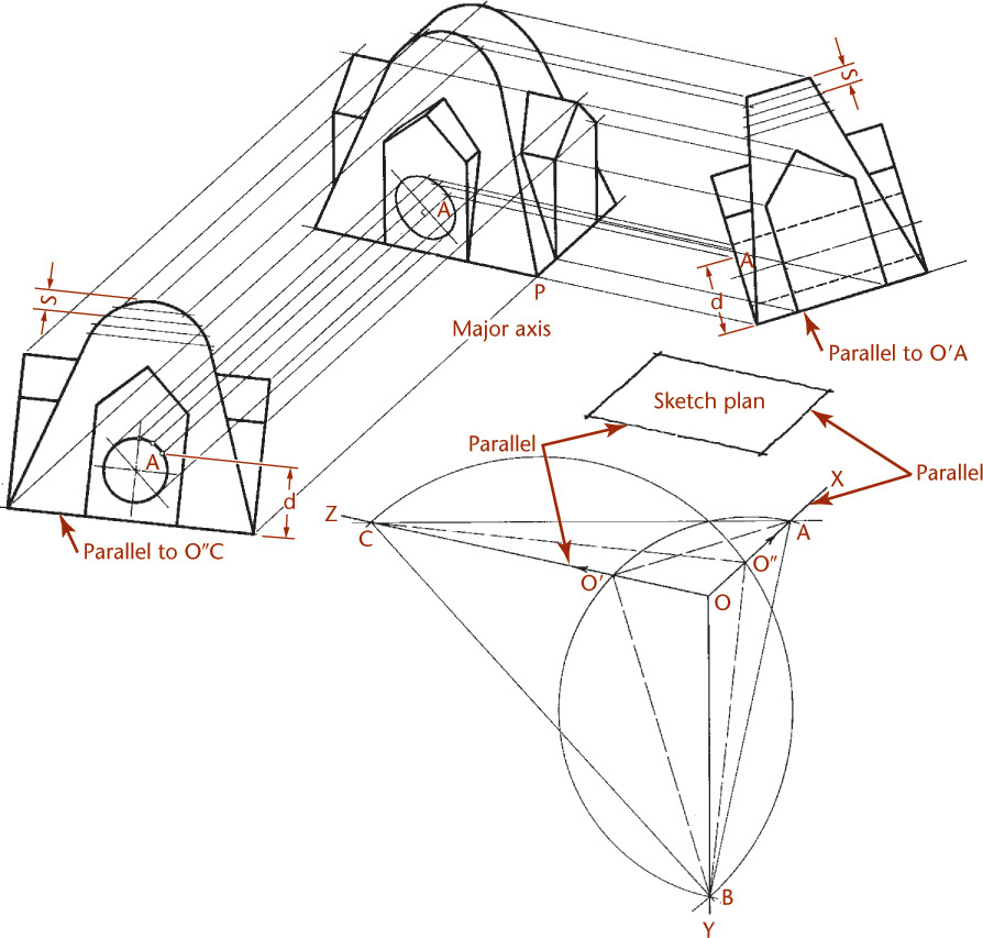
To understand how the axonometric projection in Figure 22.10 was created, examine the figure while reading through these steps.
Draw the axes with OX and OZ parallel to the sides of the sketch plan, and the remaining axis OY in a vertical position.
Revolve triangles COB and AOB, and draw the two baselines parallel to O″C and O′A.
Choose point P, the lower front corner of the axonometric drawing, at a convenient place, and draw projecting lines toward the baselines parallel to axes OX and OZ to locate their positions. You can draw the views on the baselines or even cut them apart from another drawing and fasten them in place with drafting tape.
To draw the elliptical projection of the circle, use any points, such as A, on the circle in both front and side views. Note that point A is the same altitude, d, above the baseline in both views. Draw the axonometric projection of point A by projecting lines from the two views. You can project the major and minor axes this way, or by the methods shown in Figure 22.7.
True ellipses may be drawn by any of the methods shown in Chapter 3 or with an ellipse template. An approximate ellipse is fine for most drawings.
22.7 Computer Graphics
Pictorial drawings of all sorts can be created using 3D CAD (Figures 22.11 and 22.12). To create pictorials using 2D CAD, use projection techniques similar to those presented in this chapter. The advantage of 3D CAD is that once you make a 3D model of a part or assembly, you can change the viewing direction at any time for orthographic, isometric, or perspective views. You can also apply different materials to the drawing objects and shade them to produce a high degree of realism in the pictorial view.

22.8 Oblique Projections
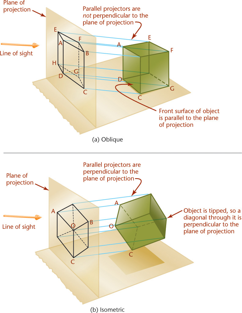
In oblique projections, the projectors are parallel to each other but are not perpendicular to the plane of projection. To create an oblique projection, orient the object so that one of its principal faces is parallel to the plane of projection, as illustrated in Figure 22.13. Bear in mind that the goal is to produce an informative drawing. Orient the surface showing the most information about the shape of the object so it is parallel to the plane of projection.
Figures 22.14, 22.15, and 22.16 show comparisons between oblique projection, orthographic projection, and isometric projection for a cube and a cylinder. In oblique projection, the front face is identical in the front orthographic view.
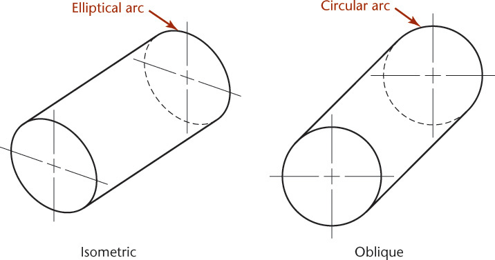
If an object is placed with one of its faces parallel to the plane of projection, the projected view will show the face true size and shape. This makes oblique drawings easier than isometric or other axonometric projection such as dimetric or trimetric for many shapes. Surfaces that are not parallel to the plane of projection will not project in true size and shape.
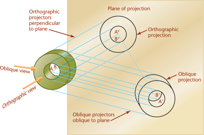
In axonometric drawings, circular shapes nearly always project as ellipses, because the principal faces are inclined to the viewing plane. If you position the object so that those surfaces are parallel to the viewing plane and draw an oblique projection, the circles will project as true shape and are easy to draw.
Oblique projections show the object from an angle where the projectors are not parallel to the viewing plane. An axis (such as AB of the cylinder in Figure 22.15) projects as a point (AVBV) in the orthographic view where the line of sight is parallel to AB. But in the oblique projection, the axis projects as line A′B′. The more nearly the direction of sight approaches being perpendicular to the plane of projection, the closer the oblique projection moves toward the orthographic projection, and the shorter A′B′ becomes.
Directions of Projectors
In Figure 22.17, the projectors make an angle of 45° with the plane of projection, so line CD′, which is perpendicular to the plane, projects true length at C′D′. If the projectors make a greater angle with the plane of projection, the oblique projection is shorter, and if the projectors make a smaller angle with the plane of projection, the oblique projection is longer. Theoretically, CD′ could project to any length from zero to infinity.
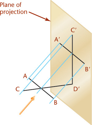
Line AB is parallel to the plane and will project true length regardless of the angle the projectors makes with the plane of projection.
In Figure 22.13, the lines AE, BF, CG, and DH are perpendicular to the plane of projection and project as parallel inclined lines A′E′, B′F′, C′G′, and D′H′ in the oblique projection. These lines on the drawing are called the receding lines. They may be any length, depending on the direction of sight.
What angle will these lines be in the drawing measured from horizontal? In Figure 22.18, line AO is perpendicular to the plane of projection, and all the projectors make angles of 45° with it; therefore, all the oblique projections like BO, CO, and DO are equal in length to line AO. You can select the projectors at any angle and still produce any desired angle with the plane of projection. The directions of the projections BO, CO, DO, and so on, are independent of the angles the projectors make with the plane of projection. Traditionally, the angle used is 45°(CO in the figure), 30°, or 60° with horizontal.

22.9 Ellipses for Oblique Drawings
It is not always possible to orient the view of an object so that all its rounded shapes are parallel to the plane of projection. For example, the object shown in Figure 22.19a has two sets of circular contours in different planes. Both cannot be simultaneously placed parallel to the plane of projection, so in the oblique projection, one of them must be viewed as an ellipse.

If you are sketching, you can just block in the enclosing rectangle and sketch the ellipse tangent to its sides. Using CAD, you can draw the ellipse by specifying its center and major and minor axes. In circumstances where a CAD system is not available, if you need an accurate ellipse, you can draw it by hand using one of the following methods.
Alternative Four-Center Ellipses
Normal four-center ellipses can be made only in an equilateral parallelogram, so they cannot be used in an oblique drawing where the receding axis is foreshortened. Instead, use this alternative four-center ellipse to approximate ellipses in oblique drawings.
Draw the ellipse on two centerlines, as shown in Figure 22.20. This is the same method as is sometimes used in isometric drawings, but in oblique drawings it appears slightly different according to the different angles of the receding lines.
First, draw the two centerlines. Then, from the center, draw a construction circle equal to the diameter of the actual hole or cylinder. The circle will intersect each centerline at two points. From the two points on one centerline, draw perpendiculars to the other centerline. Then, from the two points on the other centerline, draw perpendiculars to the first centerline. From the intersections of the perpendiculars, draw four circular arcs, as shown.
Four-Center Ellipse for Cavalier Drawings
For cavalier drawings, you can use the normal four-center ellipse method to draw ellipses (Figure 22.19b). This method can be used only in cavalier drawing because the receding axis is drawn to full scale, forming an equilateral parallelogram.
To approximate the ellipse in the angled plane, draw the enclosing parallelogram. Then, draw the perpendicular bisectors to the four sides of the parallelogram. The intersections of the perpendicular bisectors will be centers for the four circular arcs that form the approximate ellipse. If the angle of the receding lines is anything other than 30° from horizontal, as in this case, the centers of the two large arcs will not fall in the corners of the parallelogram.
When using a CAD system, you can quickly construct accurate ellipses and do not need these methods, but knowing them may be helpful for drawing in the field, or under other circumstances where CAD may not be readily available.
22.10 Offset Measurements
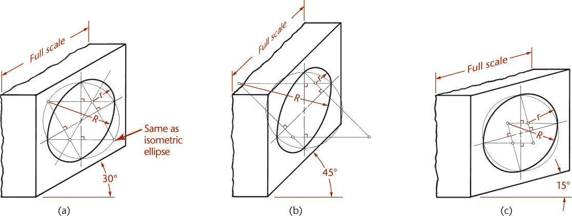
Circles, circular arcs, and other curved or irregular lines can be drawn using offset measurements, as shown in Figure 22.21. Draw the offsets on the multiview drawing of the curve (Figure 22.21a), and transfer them to the oblique drawing (Figure 22.21b). In this case, the receding axis is full scale; therefore all offset measurements are drawn full scale. The four-center ellipse could be used, but this method is more accurate.
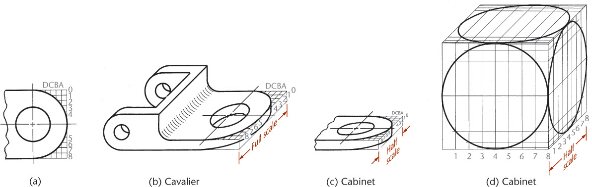
In a cabinet drawing (Figure 22.21c) or any oblique drawing where the receding axis is at a reduced scale, the offset measurements along the receding axis must be drawn to the same reduced scale. The four-center ellipse cannot be used when the receding axis is not full scale. A method of drawing ellipses in a cabinet drawing of a cube is shown in Figure 22.21d.
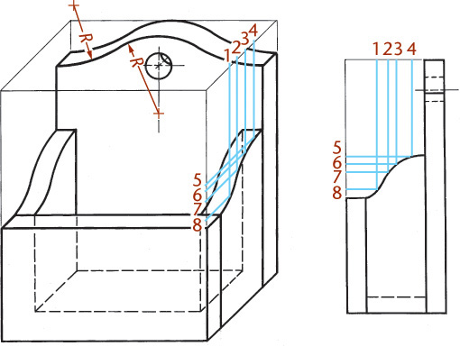
Figure 22.22 shows a free curve drawn by means of offset measurements in an oblique drawing and also illustrates hidden lines used to make the drawing clearer.
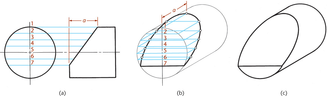
Offset measurements can be used to draw an ellipse in an inclined plane, as shown in Figure 22.23. In Figure 22.23a, parallel lines represent imaginary cutting planes. Each plane cuts a rectangular surface between the front of the cylinder and the inclined surface. These rectangles are shown in the oblique drawing in Figure 22.23b. The curve is drawn through the corner points. The final cavalier drawing is shown in Figure 22.23c.
22.11 Oblique Dimensioning
You can dimension oblique drawings in a way similar to that used for isometric drawings. Follow the general principles of dimensioning that you learned in Chapter 11.
As shown in Figure 22.24, all dimension lines, extension lines, and arrowheads must lie in the planes of the object to which they apply. You should also place the dimension values in the corresponding planes when using the aligned dimensioning system (Figure 22.24a). For the preferred unidirectional system of dimensioning, all dimension figures are horizontal and read from the bottom of the drawing (Figure 22.24b). Use vertical lettering for all pictorial dimensioning.
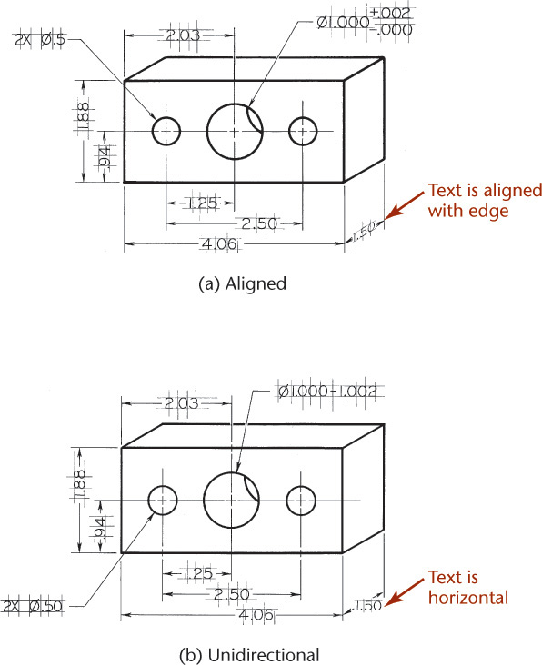
Place dimensions outside the outlines of the drawing except when clarity is improved by placing the dimensions directly on the view.
22.12 Computer Graphics
Using CAD you can easily create oblique drawings by using a snap increment and drawing in much the same way as on grid paper. If necessary, adjust for the desired amount of foreshortening along the receding axis as well as the preferred direction of the axis. You can use CAD commands to draw curves, ellipses, elliptical arcs, and other similar features. However if you need a complicated detailed pictorial, it is often easier and more accurate to create a 3D model rather than an oblique view.
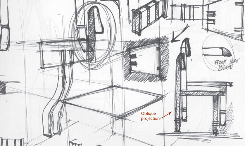
Oblique Projection in a Sketch (Courtesy of Douglas Wintin.)
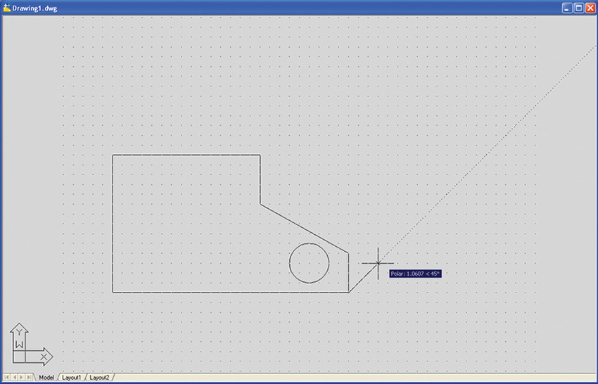
CAD at Work: Quick Oblique Drawing Using AutoCAD
You can use the snap tool available in the AutoCAD software to make a quick oblique drawing. An oblique drawing is a 2D drawing that gives the appearance of 3D by showing the object angled so that it shows all the major surfaces in one pictorial view.
To Create a Quick Oblique Drawing
Use methods similar to that for creating a sketch on paper:
1. Draw the front view of the object.
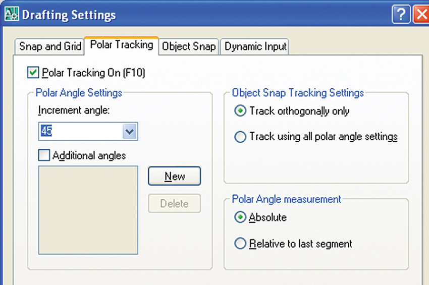
2. Use the snap increment or the polar tracking to draw one of the receding lines showing the depth of the object.
3. Copy the front surface to the back.
4. Add the receding edges.
3D solid models are rarely ever shown in oblique views. It is as quick and easy to create a 3D solid model and produce a view of that as it is to make an oblique sketch, but depending on your need, you may choose either option.
1. Draw the front view.
2. Use the region command to create 2D areas from the drawing lines.
3. Subtract the areas that are holes from the exterior.
4. View the drawing from an angle so that you can see the results when you produce the 3D part.
5. Extrude the region to create a 3D solid.
6. Orbit the drawing to change your 3D viewpoint.
Which drawing appears most realistic?
Which do you think is most useful?


(Autodesk screen shots reprinted courtesy of Autodesk, Inc.)
Chapter Summary
• An axonometric drawing is created by rotating an object about imaginary vertical and horizontal axes until three adjacent views, usually the top, front, and right-side view, can all be seen at the same time.
• Inclined surfaces and oblique surfaces must be determined by plotting the endpoints of each edge of the surface.
• Angles, irregular curves, and ellipses require special construction techniques for accurate representation.
• A common method of drawing an object in isometric is by creating an isometric box and drawing the features of the object within the box.
• Unlike perspective drawing, in which parallel lines converge on a vanishing point, parallel lines are drawn parallel in axonometric drawings.
• Oblique projection makes drawing circles in the projection plane easier than with other pictorial projection methods.
• Oblique drawings of circular features are often created by first drawing a skeleton of centerlines.
• There is usually no reason for creating oblique drawings using CAD, because isometric drawings are easier to make with CAD and appear more photorealistic.
• Oblique projection is a common sketching method because the front view is true size and true shape and easier to draw.
Review Questions
1. Why is isometric drawing more common than perspective drawing in engineering work?
2. What are the differences between axonometric projection and perspective?
3. Which type of projection places the observer at a finite distance from the object? Which types place the observer at an infinite distance?
4. Why is isometric easier to draw than dimetric or trimetric?
5. Is the four-center ellipse a true ellipse or an approximation?
6. Is an ellipse in CAD a four-center ellipse or a true conic section?
7. Can an angle on an oblique drawing be measured in the front view? In the right side view? In the top view?
8. Why are oblique drawings seldom created with CAD software?
9. Describe how to plot an irregular curve in an oblique drawing.
Chapter Exercises
Axonometric Problems
Exercises 22.1–22.9 are to be drawn axonometrically. The earlier isometric sketches may be drawn on isometric paper, and later sketches should be made on plain drawing paper.
Because many of the exercises in this chapter are of a general nature, they can also be solved using CAD. Your instructor may ask you to use CAD for specific problems.
Oblique Projection Problems
Exercises to be drawn in oblique—either cavalier or cabinet—are given in Exercises 22.10–22.14. They may be drawn freehand using graph paper or plain drawing paper as assigned by the instructor, or they may be drawn with instruments. In the latter case, all construction lines should be shown on the completed drawing.
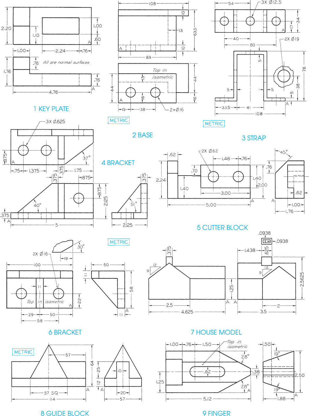
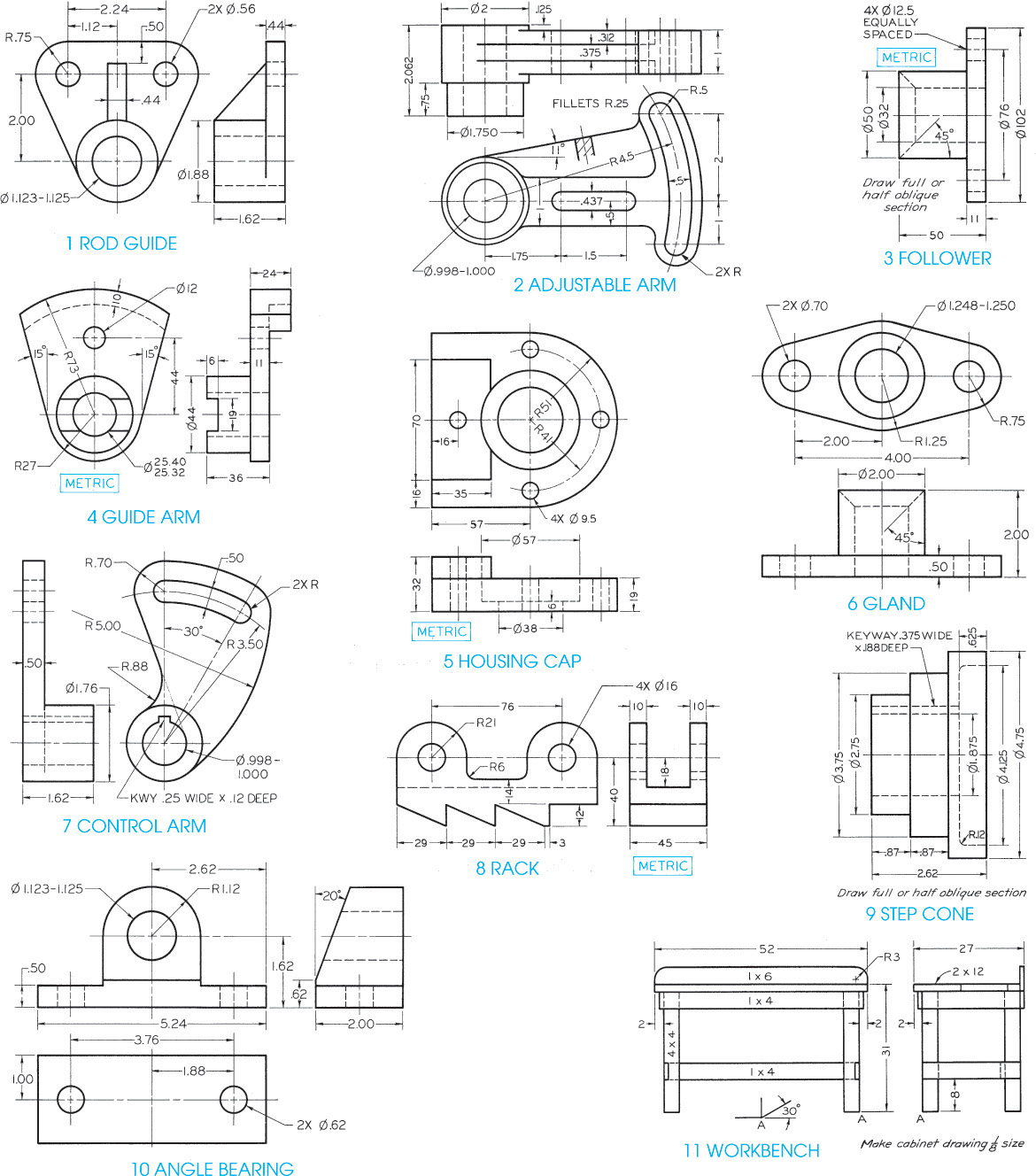
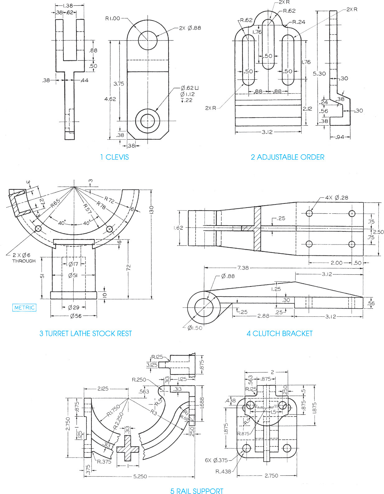
Exercise 22.1 (1) Make freehand isometric sketches. (2) Use CAD to make isometric drawings. (3) Make dimetric drawings. (4) Make trimetric drawings with axes chosen to show the objects to best advantage. Dimension your drawing only if assigned by your instructor.
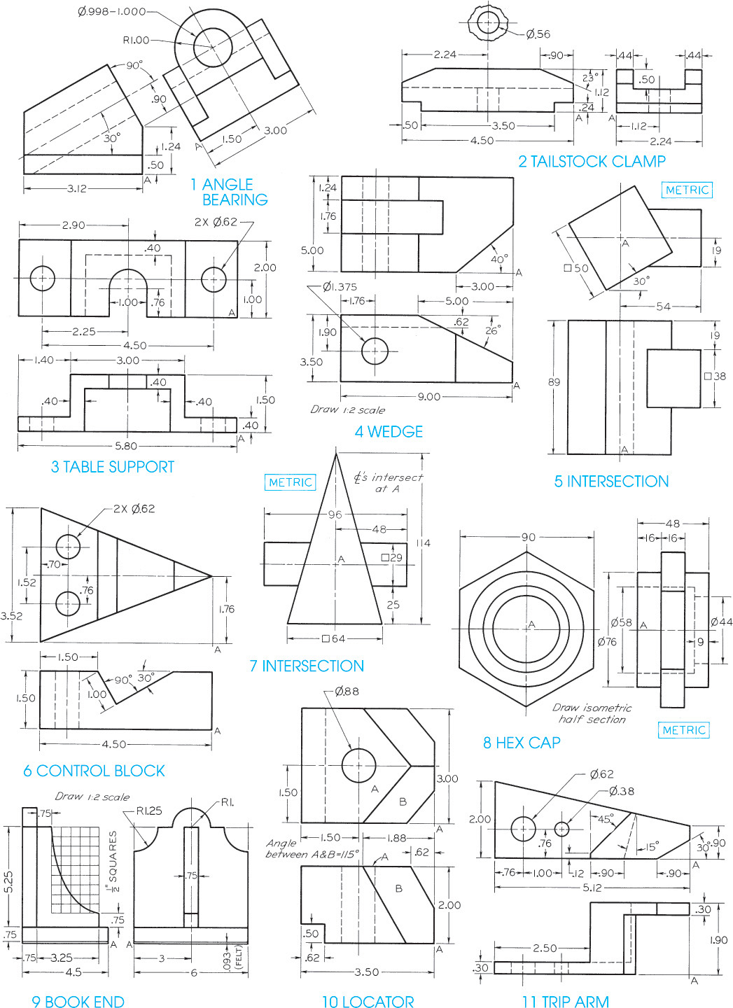
Exercise 22.2 (1) Make freehand isometric sketches. (2) Use CAD to make isometric drawings. (3) Make dimetric drawings. (4) Make trimetric drawings with axes chosen to show the objects to best advantage. Dimension your drawing only if assigned by your instructor.

Exercise 22.3 (1) Make freehand isometric sketches. (2) Use CAD to make isometric drawings. (3) Make dimetric drawings. (4) Make trimetric drawings with axes chosen to show the objects to best advantage. Dimension your drawing only if assigned by your instructor.

Exercise 22.4 (1) Make freehand isometric sketches. (2) Use CAD to make isometric drawings. (3) Make dimetric drawings. (4) Make trimetric drawings with axes chosen to show the objects to best advantage. Dimension your drawing only if assigned by your instructor.
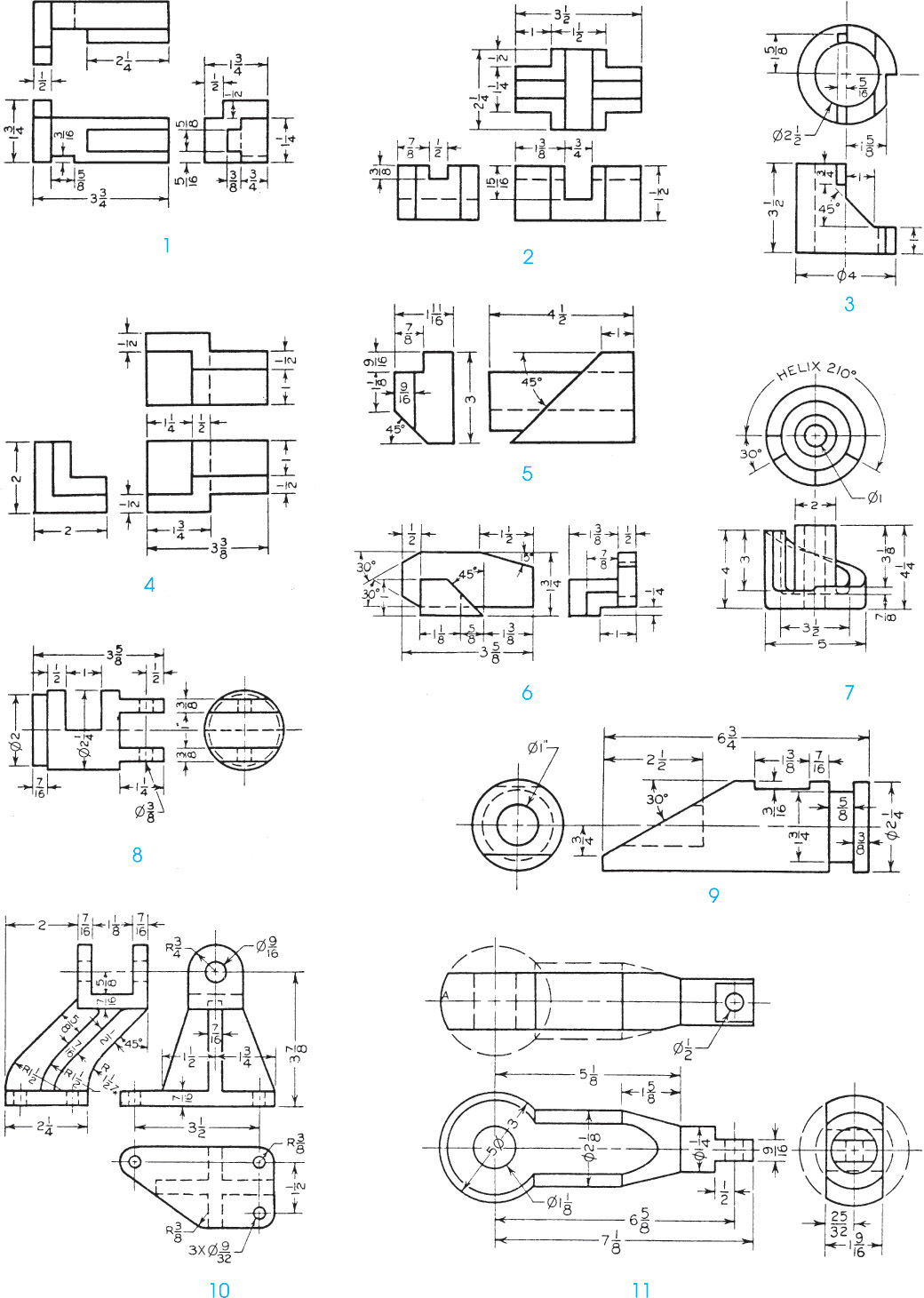
Exercise 22.5 (1) Make freehand isometric sketches. (2) Use CAD to make isometric drawings. (3) Make dimetric drawings. (4) Make trimetric drawings with axes chosen to show the objects to best advantage. Dimension your drawing only if assigned by your instructor.
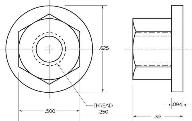
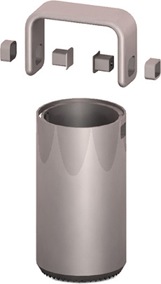
Exercise 22.6 Draw the nylon collar nut as follows. (1) Make an isometric freehand sketch. (2) Make an isometric drawing using CAD.
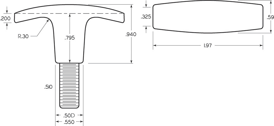
Exercise 22.7 Draw the plastic T-handle plated steel stud as follows. (1) Make a dimetric drawing using CAD. (2) Make a trimetric drawing using CAD.

Exercise 22.8 Draw the mounting plate as follows. (1) Make an isometric freehand sketch. (2) Make isometric drawings using CAD.
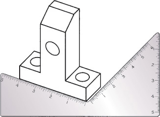
Exercise 22.9 Draw the hanger as follows. (1) Make an isometric freehand sketch. (2) Make isometric drawings using CAD.
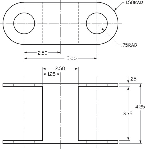
Exercise 22.10 (1) Make freehand oblique sketches. (2) Make oblique drawings using CAD. Add dimensions to your drawing only if assigned by your instructor.

Exercise 22.11 (1) Make freehand oblique sketches. (2) Make oblique drawings using CAD. Add dimensions to your drawing only if assigned by your instructor.
Exercise 22.12 (1) Make freehand oblique sketches. (2) Make oblique drawings using CAD. Add dimensions to your drawing only if assigned by your instructor.
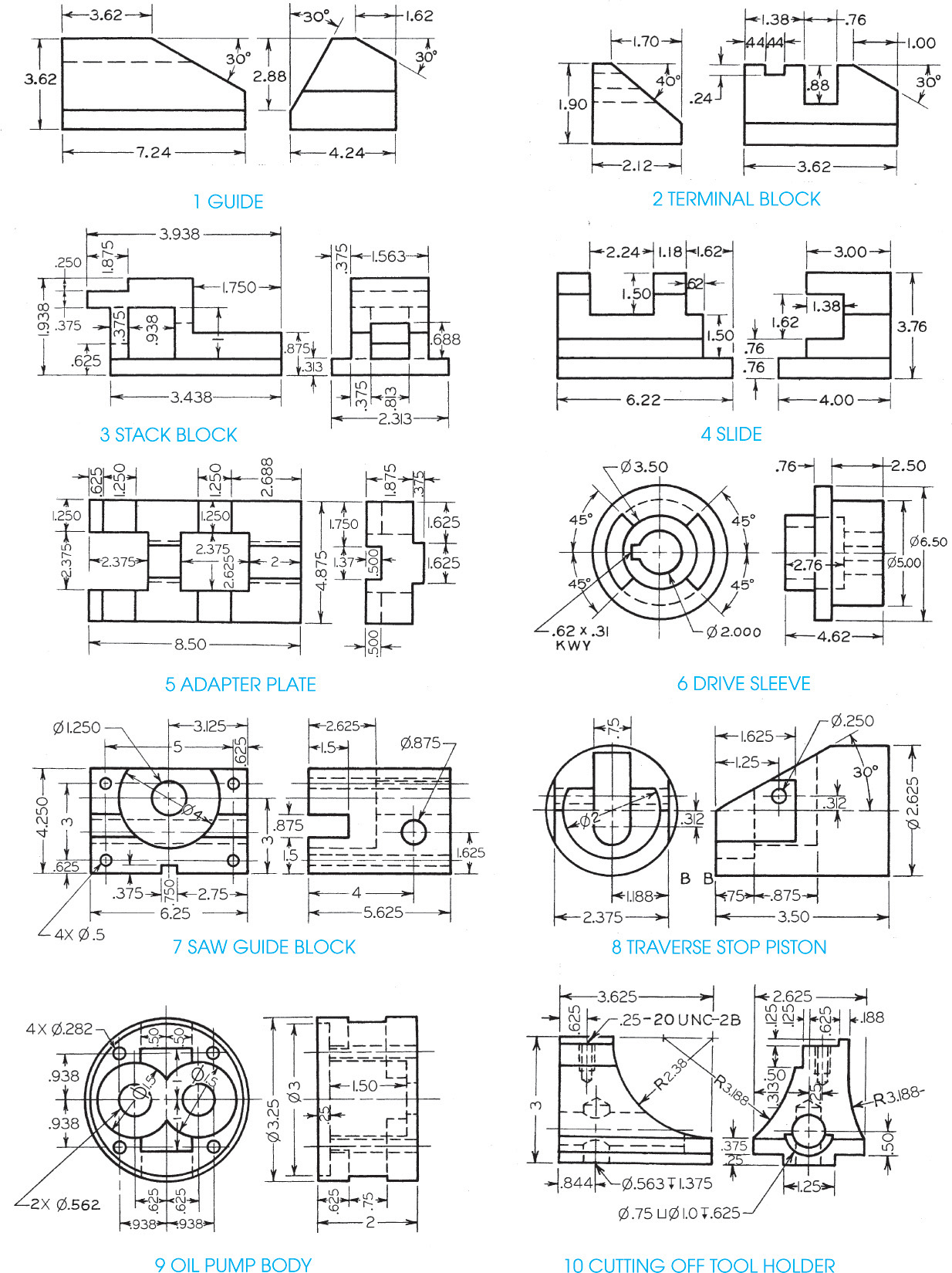
Exercise 22.13 (1) Make freehand oblique sketches. (2) Make oblique drawings using CAD. Add dimensions to your drawing only if assigned by your instructor.
Exercise 22.14 For the linear actuator, make an oblique drawing. If requested by your instructor, add the overall dimensions.