
Chapter Twenty-Three. Perspective Drawings
Objectives
After studying the material in this chapter, you should be able to:
1. Identify a drawing created using perspective projection.
2. List the differences between perspective projection and axonometric projection.
3. Create a drawing using multiview perspective.
4. Describe three types of perspective.
5. Measure distances in perspective projection.
Refer to the following standard:
• ASME Y14.4M Pictorial Drawing

The large red pipes of a thermal energy plant in Iceland vanish toward the horizon in this photograph. (Courtesy of Paul Chesley.)
Understanding Perspectives
A perspective drawing involves four main elements:
• The observer’s eye
• The object being viewed
• The plane of projection
• The projectors from the observer’s eye to all points on the object
The plane of projection is placed between the observer and the object, as shown in Figure 23.1. The perspective view is produced where the perspective projectors pierce the plane of projection.
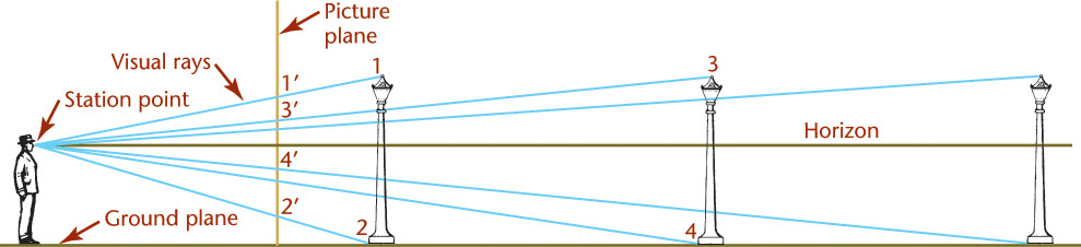
Figure 23.1 shows an observer looking along a boulevard and through an imaginary plane of projection. This plane is called the picture plane (PP). The position of the observer’s eye is called the station point (SP). The lines from the station point to the various points in the scene are the projectors, or visual rays. The visual rays pierce the picture plane giving perspectives of the points. Together, these piercing points form the perspective view of the object or the scene as viewed by the observer. Figure 23.2 shows the perspective view of the objects projected onto the picture plane from the point of view of the observer in Figure 23.1. Each lamppost projects smaller than the preceding one as it is farther from the observer. A lamppost in the picture plane would be projected in true length.
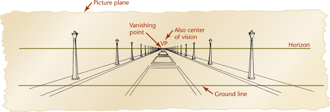
In Figure 23.1, a line represents the horizon. The horizon represents the eye level of the observer (SP). In Figure 23.1, the ground plane is the edge view of the ground on which the object usually rests. In Figure 23.2, the ground line (GL) is the intersection of the ground plane with the picture plane.
Lines that are parallel to each other but not parallel to the picture plane, such as curb lines, sidewalk lines, and lines along the tops and bottoms of the lampposts, all converge toward a single point on the horizon. This point is called the vanishing point (VP) of the lines.
The following are some rules to learn for perspective:
• All parallel lines that are not parallel to the picture plane vanish at a point.
• If these lines are parallel to the ground, the vanishing point will be on the horizon.
• Lines that are parallel to the picture plane, such as the vertical axis of each lamppost, remain parallel to one another and do not converge toward a vanishing point.
23.1 Perspective from a Multiview Projection
It is possible to draw a perspective from a multiview projection, as shown in Figure 23.3. The upper portion of the drawing shows the top view of the station point, the picture plane, the object, and the visual rays. The right-side view shows the same station point, picture plane, object, and visual rays.
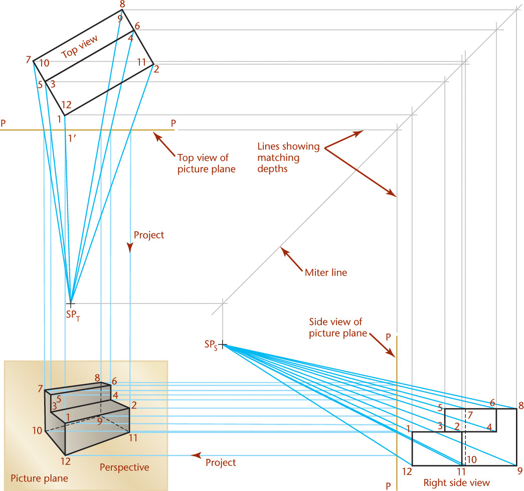
In the front view, the picture plane coincides with the plane of the paper, and the perspective view is drawn on it. Depth measurements are transferred from the top view to the side view, using the usual multiview projection techniques.
To show point 1 in the perspective view, you would:
1. Draw a visual ray in the top view from SPT to point 1 on the object in the top view.
2. Draw a projection line downward into the perspective view where your ray crosses the picture plane (1′).
3. Locate point 1 in the perspective view where your vertical line meets a similar projection line from the side view.
Find the perspective locations of other points in the same way and then draw the visible and hidden lines between the endpoints you projected into the perspective view.
Examine the perspective drawing shown in Figure 23.3. All parallel lines that are also parallel to the picture plane (the vertical lines) remain parallel and do not converge. The other two sets of parallel lines converge toward vanishing points. If the converging lines from the edges in the perspective view were extended, they would meet at two vanishing points (one for each set of parallel lines, as illustrated in Figure 23.4).

It is possible to construct the perspective of any object this way, but this method is rather cumbersome because the top and side views usually show the object in an angled position.
23.2 Nonrotated Side View Method for Perspective
Figure 23.4 shows a simpler construction for a perspective. The upper portion of the drawing shows the top views of the station point, picture plane, and the object. The lines SP-1, SP-2, SP-3, and SP-4 are the top views of the visual rays.
Details of the actual side view for the given top view are not required. Any side view drawn in that location can provide the necessary height measurements.
The perspective view is drawn on the picture plane where the front view would usually be located.
The side view shows the edge view of the ground line on which the object is resting.
The perspective view shows the intersection of the ground plane with the picture plane. In the perspective view, the horizon shows as a horizontal line. Since the horizon plane passes through the observer’s eye, or SP, it is drawn at the level of the eye—that is, at the distance above the ground line representing (to scale) the height of the eye above the ground.
The center of vision (CV), is the orthographic projection (or front view) of the station point on the picture plane of the perspective view. Because the horizon is at eye level, the center of vision will always be on the horizon, except in three-point perspectives.
As shown in Figure 23.4, you would locate the center of vision (CV′) in the top view by projecting a perpendicular line from the station point (SP) to the picture plane (PP). You would locate CV in the front view by projecting downward from CV′ to the horizon.
Note that vertical heights can be measured only in the picture plane. If the front vertical edge 1′-5′ of the object were actually situated in the picture plane, the vertical height would be full size. If the vertical edge is behind the picture plane, you can extend a plane of the object, such as surface 1-2-5-6, forward until it intersects the picture plane (line TQ). The line TQ is called a measuring line. The true height (SQ) of line 1-5 can be measured with a scale or projected from the side view as shown.
If your drawing area is not large enough, one vanishing point, such as VPR, may be off the sheet. By using one vanishing point VPL and projecting down from the piercing points in PP, vanishing point VPR may be eliminated. The second vanishing point allows for checking, so it is best to draw it if space permits.
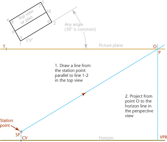
Drawing perspective views of horizontal lines that are not parallel to the picture plan is not difficult if you understand the process. Steps for finding line 1′-2′ in the perspective view are detailed on the next page.
Drawing Perspectives of Horizontal Straight Lines That are not Parallel to the Picture Plane
![]() Find the piercing point of line 1-2.
Find the piercing point of line 1-2.
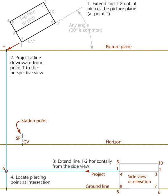
![]() Find the vanishing point for line 1′-2′.
Find the vanishing point for line 1′-2′.
![]() Draw a line from the piercing point of line 1-2 in the perspective view (point S) to its vanishing point.
Draw a line from the piercing point of line 1-2 in the perspective view (point S) to its vanishing point.

![]() Locate the endpoints of the line 1-2 in the perspective view. Project down from the piercing points of the visual rays in the picture plane (PP) to find the endpoints of line 1-2 as it appears in the perspective view (1′ and 2′), or draw the perspectives of the remaining horizontal edges of the object to find where they intersect. Better yet, use both methods to check your work.
Locate the endpoints of the line 1-2 in the perspective view. Project down from the piercing points of the visual rays in the picture plane (PP) to find the endpoints of line 1-2 as it appears in the perspective view (1′ and 2′), or draw the perspectives of the remaining horizontal edges of the object to find where they intersect. Better yet, use both methods to check your work.

![]() After you draw all horizontal edges in the perspective, draw the vertical and inclined edges to complete the perspective as shown in Figure 23.4.
After you draw all horizontal edges in the perspective, draw the vertical and inclined edges to complete the perspective as shown in Figure 23.4.
23.3 Drawing an Angular Perspective
Because objects are defined principally by edges that are straight lines, drawing a complex perspective is just a series of drawings of the perspective of lines. If you can draw the perspective of a line, you can draw the perspective of any object, no matter how complex.
23.4 Position of the Station Point
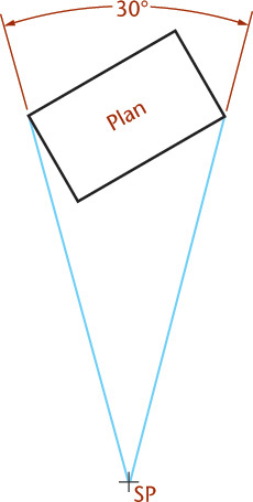
The centerline of the cone of visual rays should be directed toward the approximate center, or center of interest, of the object. In two-point perspective (Figure 23.4), locating the station point (SP) in the plan view slightly to the left and not directly in front of the center of the object produces a better view, as if the object is seen at a glance without turning the head. Use a cone of rays with its vertex at the station point and a vertical angle of about 30° entirely enclosing the object, as shown in Figure 23.5, to produce this effect.
The station point (SP) does not appear in the perspective view in Figure 23.4, because the station point is in front of the picture plane. The orthographic projection center of vision (CV) of the station point (SP) in the picture plane shows the height of the station point measured from the ground plane. It also shows the altitude of the station point, because the horizon is at eye level.
Draw the horizon in the perspective view at the same level above the ground line that you want to use as the height of the station point. Most small and medium-size objects, such as machine parts or furniture, look best when the station point is slightly above the top of the object. Large objects, such as buildings, are usually viewed from a station point at about the height of the eye above the ground, or about 5′6″.
23.5 Location of the Picture Plane
The picture plane can be placed:
• In front of the object, as in Figure 23.6b and Figure 23.6c, which is the most common.
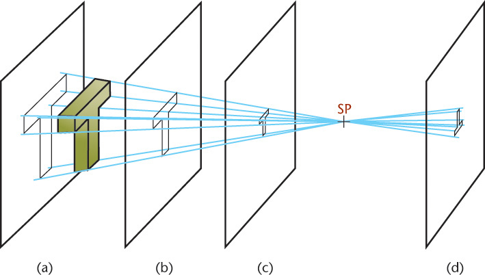
• Behind the object, as in Figure 23.7a.
• Behind the station point (SP), as in Figure 23.6d, in which case the perspective is reversed, as through a camera lens.
The perspectives in Figure 23.6 differ in size but not in proportion. As in Figures 23.6b and 23.6c, the farther the plane is from the object, the smaller the perspective drawing will be. This distance controls the scale of the perspective. Usually, the object is placed with the front corner in the picture plane to make vertical measurements easier.
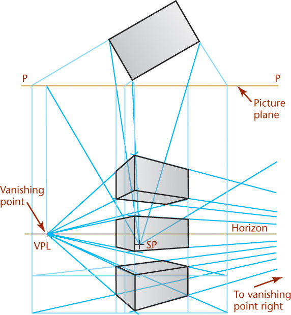
23.6 Bird’s-Eye View or Worm’s-Eye View
The horizon is level with the observer’s eye, so controlling the location for the horizon line controls whether the perspective view appears from above or below the object. The horizon line is defined by the observer’s point of view.
To produce a perspective view that shows the objects as though viewed from above, place the object below the horizon line. To produce a perspective view that shows the object as though viewed from below, place the object above the horizon line. This is not the case in three-point perspective (see Section 23.11). The differences in effect produced by placing the object on, above, or below the horizon are shown in Figure 23.7.
23.7 The Three Types of Perspectives
Perspective drawings are classified according to their number of vanishing points, which are determined by the position of the object with respect to the picture plane.
If the object is situated with one face parallel to the plane of projection, only one vanishing point is required, and the result is a one-point perspective, or parallel perspective.
If the object is situated at an angle with the picture plane but with vertical edges parallel to the picture plane, two vanishing points are required, and the result is a two-point perspective, or an angular perspective. This is the most common type of perspective drawing.
If the object is situated so that no principal faces or edges are parallel to the picture plane, three vanishing points are necessary, and the result is a three-point perspective.
23.8 One-Point Perspective
In one-point perspective, orient the object so two sets of its principal edges are parallel to the picture plane (essentially a flat surface parallel to the picture plane) and the third set is perpendicular to the picture plane. This third set of parallel lines will converge toward a single vanishing point in perspective.
Figure 23.8 shows the object with one face parallel to the picture plane. If desired, this face could be placed in the picture plane. The piercing points of the eight edges perpendicular to the picture plane (PP) are found by extending them to PP and then projecting downward to the level of the lines as projected across from the elevation view.
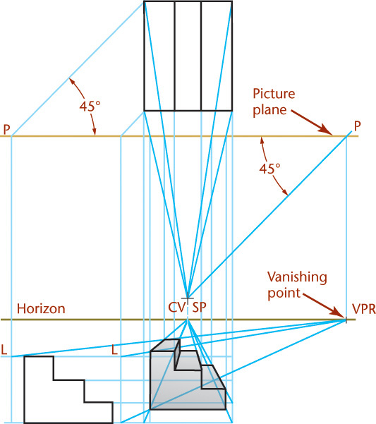
To find the vanishing points (VP) of these lines, draw a visual ray from the station point (SP) parallel to the lines (as in Step 2 on page W905). The vanishing point of all lines perpendicular to the picture plane (PP) is in the center of vision (CV). Connect the eight piercing points with the vanishing point (which is also the center of vision) to find the directions for the perspective lines of the eight edges.
To show the actual lengths of the edges of the object along the perspective lines, draw horizontal lines from the endpoints of one of the edges in the top view and at any desired angle with the picture plane (for this example, 45°). Find the piercing points and the vanishing point VPR of these lines and draw the perspectives of the lines. The intersections of these lines with the perspectives of the corresponding edges of the object produce the length of the receding edges. Use them to complete the perspective of the object.
Building interiors are sometimes shown using parallel perspective.
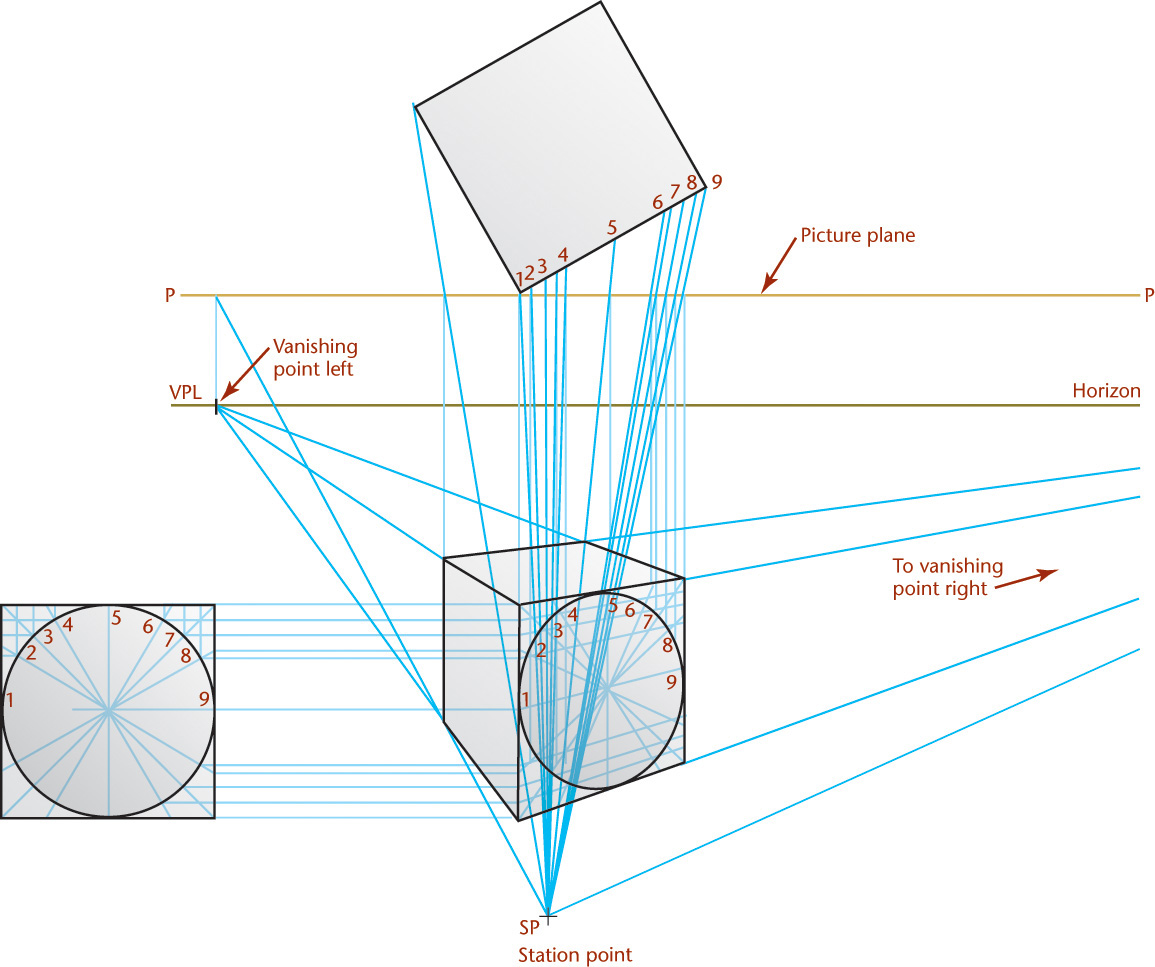
23.9 One-Point Perspective of a Cylindrical Shape
A one-point perspective representing a cylindrical machine part is shown in Figure 23.9. The front surface of the cylinder is placed in the picture plane. All circular shapes are parallel to the picture plane, and they project as circles and circular arcs in the perspective. The station point (SP) is located in front and to one side of the object. The horizon is placed above the ground line. The single vanishing point is on the horizon in the center of vision.

The two circles and the keyway in the front surface of the object are drawn true shape because they lie in parallel to the view as they are in the picture plane. The circles are drawn with the center at point O′. To locate the center of the large arc in perspective (R′), draw a visual ray from SP to R in the top view. Then, from the intersection of the ray with the picture plane (X), project down to the centerline of the large cylinder, to find the center of the arc in the perspective.
To find the radius T′W′ at the right end of the perspective view, draw visual rays SP-T and SP-W, and from their intersections with the picture plane (PP), project down to T′ and W′ on the horizontal centerline of the hole.
23.10 Two-Point Perspective
In two-point perspective, the object is oriented so that one set of parallel edges is vertical and has no vanishing point, whereas the two other sets have vanishing points. Two-point perspectives are often used to show buildings in an architectural drawing, or large structures in civil engineering, such as dams or bridges, especially for client presentation drawings.
The perspective drawing of a small building is shown in Figure 23.10. To make it easier to draw two point perspective:
1. Show an edge of the object in the picture plane so that measurements may be made directly from it.
2. Orient the object so that its faces make unequal angles with the picture plane; for example, one angle may be 30° and the other 60°.
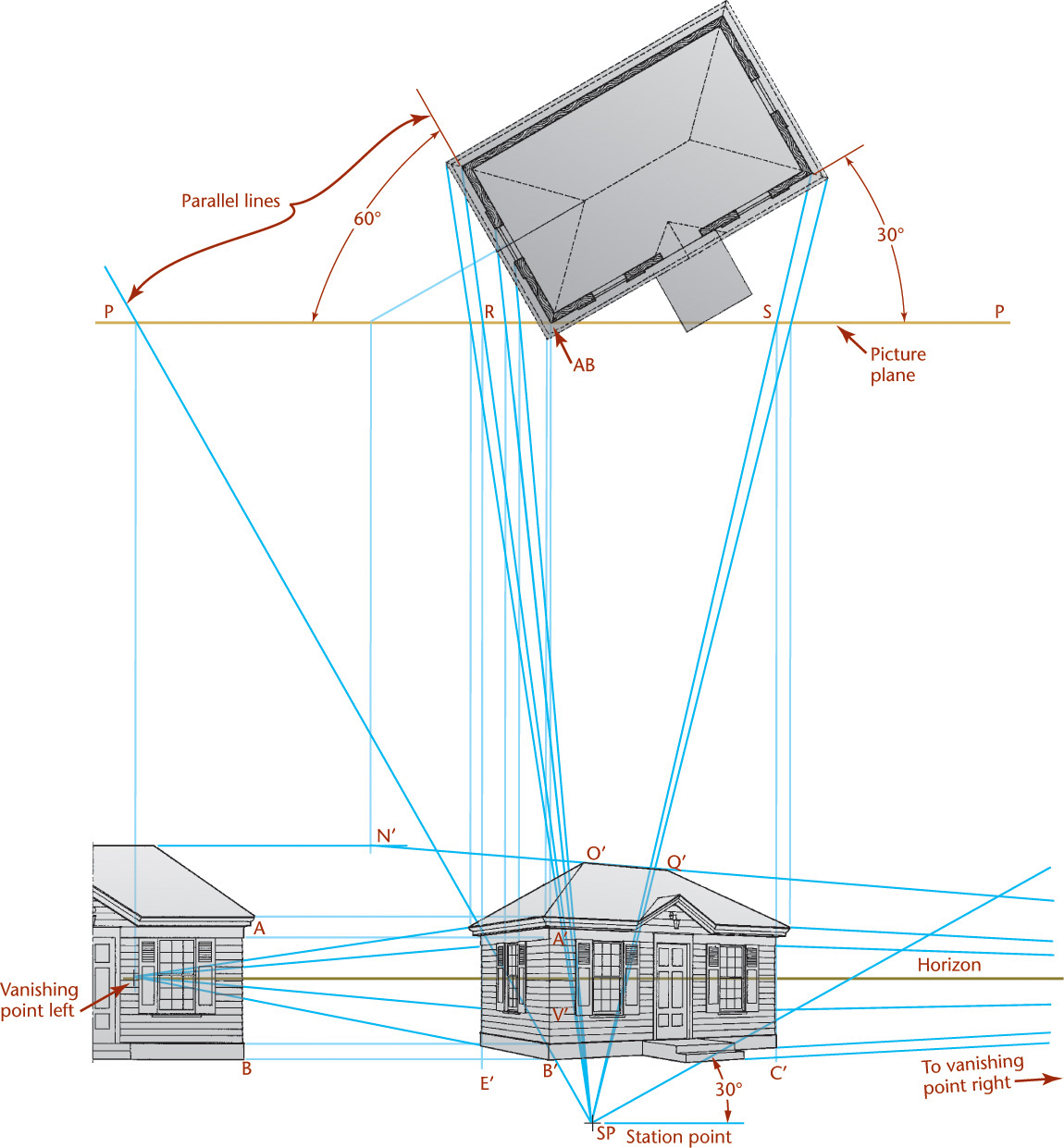
The front corner (AB) lies in the picture plane (PP). It will be full scale in the perspective view (A′B′). To draw it, project downward from the top view (plan view) and across from the side view (elevation view). Draw visual rays from the station point to the corners of the building in the top view. Project these corners to the picture plane in the top view (S and R). Then, draw the vertical lines (S-C′ and R-E′) from the intersections S and R to locate the corners in the perspective view where they will appear as vertical lines. The perspectives of the tops of the windows and the door are determined by the lines A′-VPR and A′-VPL. Their widths and lateral spacings are determined by projecting downward from the intersections with the picture plane of the respective visual rays. The bottom lines of the windows are determined by the lines V′-VPR and V′-VPL.
Find the perspective view of the roof ridge line by joining N′, projected down from the point where the ridge line pierces the picture plane, and VPR. Find the ridge endpoints O′ and Q′ by projecting down from the intersections of the visual rays with the picture plane, or by drawing the perspectives of any two lines intersecting at the vanishing points. Complete the perspective of the roof by joining the points O′ and Q′ to the ends of the eaves.
Tip
When multiview drawings are already available, tape their top (plan) and side (elevation) views in position, and use them to construct the perspective. When you are finished, remove the taped portions.
23.11 Three-Point Perspective
In three point perspective, the object is placed so that none of its principal faces or edges are parallel to the picture plane. This means that each of the three sets of parallel edges will have a separate vanishing point (Figure 23.11). The picture plane is approximately perpendicular to the centerline of the cone of visual rays.
In this figure, think of the paper as the picture plane, with the object behind the paper and placed so that all its edges make an angle with the picture plane. The center of vision (CV) represents the orthographic location of your eye, or the station point, on the picture plane. The vanishing points P, Q, and R are lines drawn from a station point parallel to the principal axes of the object and then projected to locate their piercing points in the picture planes.
Remember that to find the vanishing point of a line in any type of perspective you draw a visual ray, or line, from the station point parallel to that edge of the object, then find the piercing point of this ray in the picture plane. When the object is rectangular, these lines to the vanishing points are at right angles to each other exactly, as the axes are in axonometric projection. The lines PQ, QR, and RP are perpendicular, respectively, to CV-R, CV-P, and CV-Q and are the vanishing traces, or horizon lines, of planes through the station point (SP) parallel to the principal faces of the object.
The imaginary corner O is assumed in the picture plane and may coincide with CV; but as a rule, the front corner is placed at one side near CV, showing the observer’s position relative to the object’s corner.
In this method you draw the perspective directly from measurements and not projected from views. Now that you have the background information, follow these steps to create a general three-point perspective of the drawing shown in Figure 23.11.
Near the center of the paper, make a light mark that you will use as the center of view (CV).
Above the center of vision (for a bird’s-eye view), sketch a horizontal line to use as the horizon line.
Extend a light line from the center of view (CV) to the right and left vanishing points on the horizon line (Q and P).
Extend a light line from the center of view (CV) to a vanishing point below the object (R).
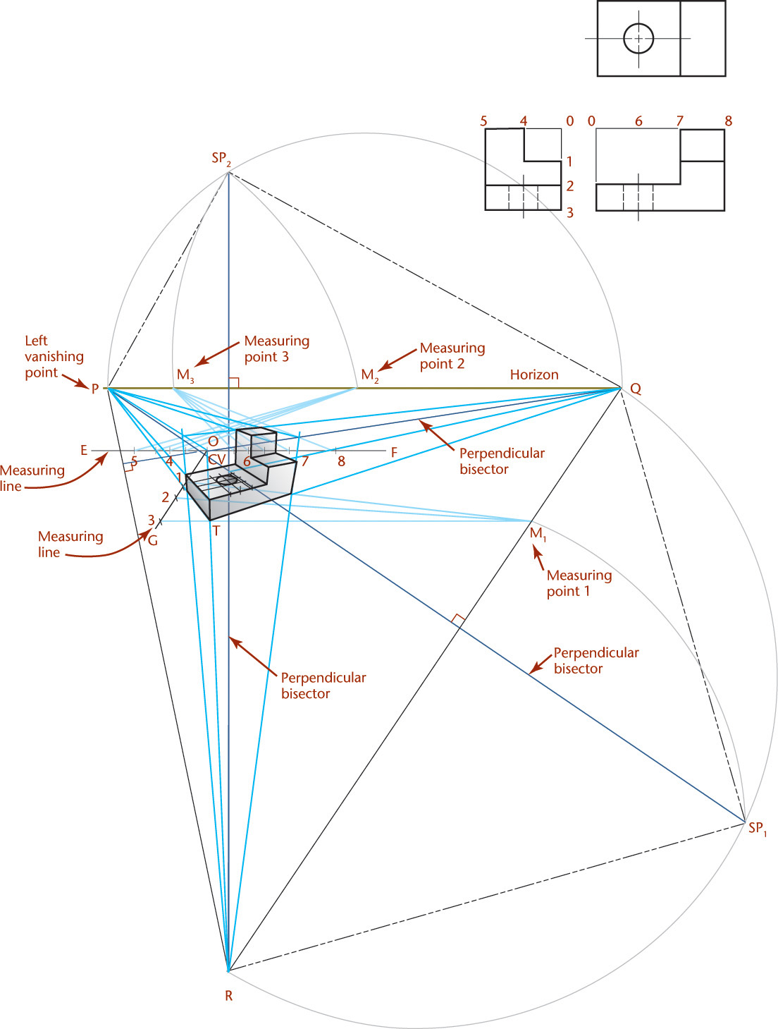
Connect these three vanishing points with straight lines to form a triangle. Perpendicular lines from each vanishing point to the opposite side will cross at the center of vision (CV).
Construct the station points by extending these perpendicular bisectors to find SP1 and SP2.
Draw lines SP1-R, SP1-Q, SP2-P, and SP2-Q.
Draw a line from vanishing point Q parallel to SP1-R. This will be the front line of the perspective object.
Draw a line from vanishing point P parallel to SP2-Q. This will be the left line of the perspective object.
Extend a line from the intersection of the two lines you just drew (from point O) to vanishing point R. This will be the height perspective line of the object.
The dimensions of the object are given by the three views, and these will be set off on measuring lines GO, EO, and OF. The measuring lines EO and OF are drawn parallel to the vanishing trace PQ, and the measuring line GO is drawn parallel to RQ. These measuring lines are actually the lines of intersection of principal surfaces of the object, extended, with the picture plane (PP). Because these lines are in the picture plane (PP), true measurements of the object can be made along them.
Three measuring points M1, M2, and M3 are used along with the measuring lines. To locate M1, revolve triangle CV-R-Q about RQ as an axis. Because it is a right triangle, it can be constructed true size using R as the center and R-SP1 as the radius and drawing arc SP1-M1, as shown. M1 is the measuring point for the measuring line GO. Measuring points M2 and M3 are found in a similar manner.
Height dimensions, from the given views, are measured full size or to any desired scale, along measuring line GO, at points 3, 2, and 1. From these points, draw lines to M1. Heights on the perspective drawing are the intersections of these lines with the perspective front corner (O) of the object. Similarly, the true depth of the object is set off on measuring line EO from 0 to 5, and the true width is set off on measuring line OF from 0 to 8. Construct the intermediate points in a similar manner.
Tip
You can sketch a three-point perspective by selecting the vanishing points and finding the center of vision by drawing the perpendicular bisectors. If you place the object at the center of vision, the edge lines will recede from that point toward the vanishing points. You can estimate proportionate distances to create a sketch that has a pleasing appearance.
23.12 Measurements in Perspective
Remember: All lines in the picture plane are shown in their true lengths, and all lines behind the picture plane are foreshortened.
To draw the perspective of a line of telephone poles (Figure 23.12), use the following method.
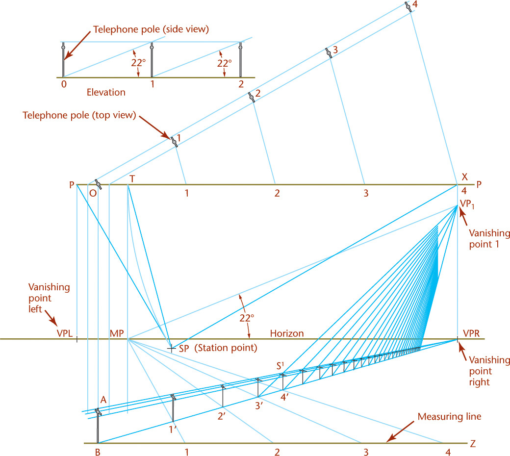
Use line OB, which represents the line of intersection of the picture plane (PP) with the vertical plane containing the poles. In this line, the height AB of a pole is measured directly to the desired scale. All the heights in the perspective drawing of all the poles can be constructed by drawing lines from A and B to the vanishing point (VPR).
To locate the bottoms of the poles along the line B-VPR, measure along the picture plane (PP) the distances 0-1, 1-2, 2-3, ..., equal to the distance from pole to pole.
Draw the lines 1-1, 2-2, 3-3, ..., that form a series of isosceles triangles 0-1-1, 0-2-2, 0-3-3, .... The lines 1-1, 2-2, 3-3, ..., are parallel to each other and therefore have a common vanishing point (MP). Locate the vanishing point by drawing from the station point (SP) a line to point T (SP–T) parallel to the lines 1-1, 2-2, 3-3, ..., and finding its piercing point in the picture plane (PP) to use as the measuring point (MP). Because line SP-X is parallel to the line of poles 1-2-3, ..., the triangle SP-X-T is an isosceles triangle, and T is the top view of MP. Locate point T by measuring the distance X-T equal to SP-X or by drawing the arc SP-T with its center at X and radius SP-X.
From the measuring point MP, find the piercing points in the picture plane (PP) of lines 1-1, 2-2, 3-3, ..., and draw their perspectives as shown. Because these lines are horizontal lines, their piercing points are in a horizontal ground line BZ in the picture plane at the bottom of the drawing.
The true distances between the poles can be measured along line BZ. BZ is used as a measuring line. Use the intersections 1′, 2′, 3′, ..., of the perspectives of the lines 1-1, 2-2, 3-3, ..., with the line B-VPR to provide the spacing of the poles.
Only a few measurements may be made along the measuring line BZ that are within the limits of the drawing. For additional measurements, you can use the diagonal method of spacing as shown.
Because all diagonals from the bottom of each pole to the top of the succeeding pole are parallel, they have a common vanishing point, VP1. This information leads to using the diagonal method to make measurements.
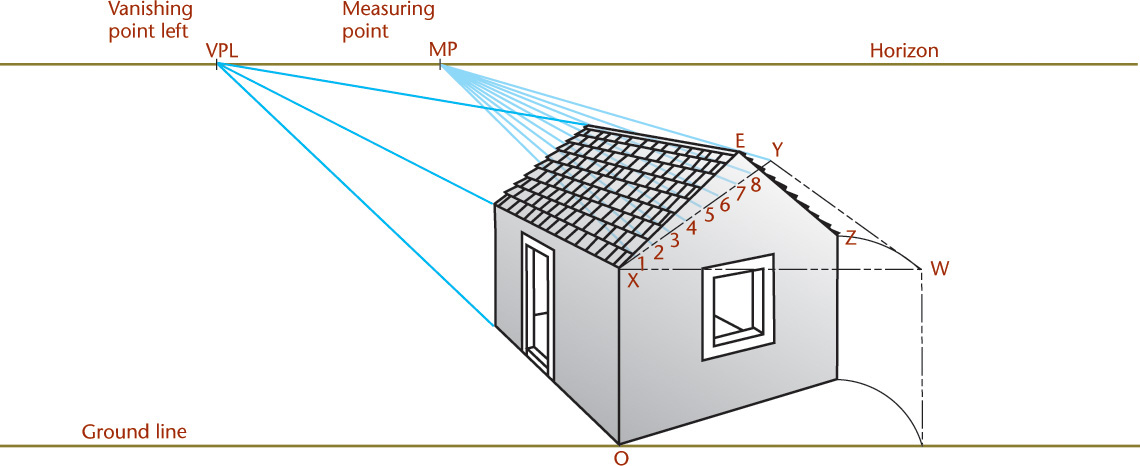
23.13 Direct Measurements Along Inclined Lines
The method of direct measurements may also be applied to lines inclined to the picture plane and to the ground plane, as illustrated in Figure 23.13. It shows line XE, which pierces the picture plane at X. If you revolve the end of the house about a vertical axis XO into the picture plane, line XE will be shown true length and tipped as shown at XY. This line XY may be used as the measuring line for XE. Next find the corresponding measuring point MP. The line YE is the horizontal base of an isosceles triangle having its vertex at X, and a line drawn parallel to it through SP will determine MP, as described for Figure 23.12.
Spotlight: Perspective Sketching
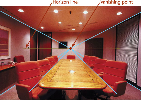
As you create perspective sketches, lightly blocking in the ground line, horizon line, and vanishing point makes it easier to create a realistic pictorial appearance and is quicker than trying to draw angles of the receding lines through repeated trial and error.
Bear in mind that the distance between the ground line and the horizon line alter the appearance of the view. If you select more commonly seen placements for the ground line, horizon line, and vanishing points, your perspectives will appear more as the subject would appear in real life.
To familiarize yourself with perspectives that look realistic, examine existing drawings, paintings, and photographs, and practice identifying the ground line, horizon line, and vanishing point.
You can place a sheet of tracing paper over a photo and, using a ruler, extend projectors from the receding lines to find the vanishing point. Or draw directly on the photos in old newspapers that you are planning to recycle. Eventually, you won’t need a ruler to quickly identify the vanishing point for an image. Remember, the vanishing point may not always be on the paper.
(Courtesy of GILLIANNE TEDDER/Photolibrary.com.)
23.14 Vanishing Points of Inclined Lines
To find the vanishing point of an inclined line, determine the piercing point in the picture plane (PP) of a line drawn from the station point (SP) parallel to the given line.
Figure 23.14 shows the perspective of a small building. Use this method to determine the vanishing point of the inclined roof line C′E′.

A plane that passes through the station point and is parallel to the end of the house (plan view) would intersect the picture plane (PP) in the line XY, through VPL, and be perpendicular to the horizon.
Because the line drawn from SP parallel to C′E′ (in space) is in the plane SP-X-Y, it will pierce the picture plane (PP) at some point T in XY. To find the point T, revolve plane SP-X-Y about the line XY as an axis into the picture plane (PP). The point SP will fall on the horizon at point O in the top view and MR in the front view.
From point MR, draw the revolved position of the line SP-T (now MR-T) making an angle of 30° with the horizon and determining point T. This point T is the vanishing point of the line C′E′ and of all lines parallel to that line. The vanishing point S of the line D′E′ is in line XY, because D′E′ is in the same vertical plane as the line C′E′. Vanishing point S is as far below the horizon as T is above the horizon, because the line E′D′ slopes downward at the same angle at which the line C′E′ slopes upward.
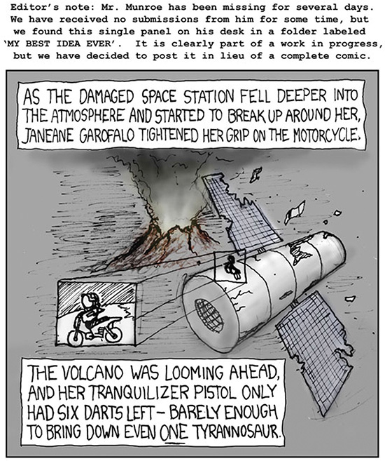
Known for drawing stick figures in his “Webcomic of Romance, Sarcasm, Math and Language” xkcd creator Randall Munroe uses perspective drawing skill in this cartoon. (Courtesy of Randall Munroe.)
23.15 Inclined Lines in Perspective, Joining Endpoint Method
The perspective drawing of inclined lines can be found without finding the vanishing points, by finding the perspectives of the endpoints and joining them. The perspective of any point may be determined by finding the perspectives of any two lines intersecting at the point. Obviously, it would be best to use horizontal lines, parallel to lines whose vanishing points are already in the drawing. For example, in Figure 23.14, to find the perspective of the inclined line EC, the point E′ is the intersection of the horizontal lines R′-VPR and B′-VPL. Point C′ is already established, because it is in the picture plane; but if it were not, it could be easily found in the same manner. The perspective of the inclined line EC is the line joining the perspectives of the endpoints E′ and C′.
23.16 Curves and Circles in Perspective
If a circle is parallel to the picture plane, its perspective is a circle. If the circle is inclined to the picture plane, its perspective drawing may be any one of the conic sections where the base of the cone is the given circle, the vertex is the station point (SP), and the cutting plane is the picture plane (PP). The centerline of the cone of rays is usually approximately perpendicular to the picture plane, so the perspective will usually be an ellipse.
The ellipse may be drawn using lines intersecting the circle, as shown in Figure 23.15. A convenient method for determining the perspective of any planar curve is shown in Figure 23.16.
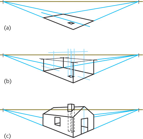
23.17 The Perspective Plan Method
You can draw a perspective by first drawing the perspective of the plan of the object (Figure 23.17a), then adding the vertical lines (Figure 23.17b), and finally adding the connecting lines (Figure 23.17c). When the drawing is complicated, the super-imposition of the perspective on the perspective plan causes a confusion of lines. Often, drawing the perspective of the plan either above or below its normal location can help when you are using it to locate the vertical measurements. One possible position of the perspective plan is shown in Figure 23.17. The use of the perspective plan below the perspective is shown in Figure 23.18.
The chief advantages of the perspective plan method over the ordinary plan method are that the vertical lines of the perspective can be spaced more accurately and that a considerable portion of the construction can be made above or below the perspective drawing, avoiding many confusing lines.
When the perspective plan method is used, you can omit the ordinary plan view and measuring points that would be used to determine distances along horizontal edges in the perspective.
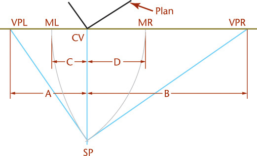
23.18 Perspective Diagram
You can use drawing methods to figure out the spacing of vanishing points and measuring points. You can also calculate the locations. In Figure 23.19, a simple diagram of the plan layout shows the position of the object, the picture plane, the station point, and the constructions for finding the vanishing points and measuring points for the problem in Figure 23.18. The complete plan need not be drawn. Use a diagram drawn to any small convenient scale. Vanishing points and measuring points should be measured in the perspective to the larger scale desired.
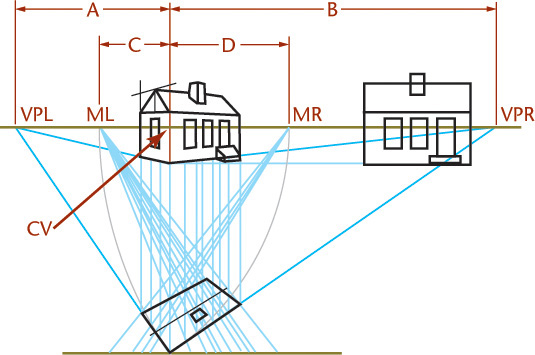
Often, structures are oriented in one of a limited number of simple positions with reference to the picture plane, such as 30° × 60°, 45° × 45°, and 20° × 70°. You can create a table of measurements for locating vanishing points and measuring points to avoid tedious construction of each drawing.
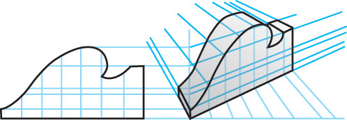
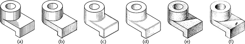
23.19 Shading
Shading pictorial drawings can be very effective in describing the shapes of objects in display drawings, patent drawings, and other pictorial drawings. Ordinary working drawings are not shaded.
Because the purpose of an industrial pictorial drawing is to show the shape clearly, the shading should be simple, should reproduce well, and should be limited to producing a clear picture. Some of the common types of shading are shown in Figure 23.20. Pencil or ink lines are drawn mechanically (Figure 23.20a) or freehand (Figure 23.20b). Two methods of shading fillets and rounds are shown in Figures 23.20c and d. Shading produced with pen dots is shown in Figure 23.20e. Pencil “tone” shading is shown in Figure 23.20f; note that it gives poor results when copied xerographically.
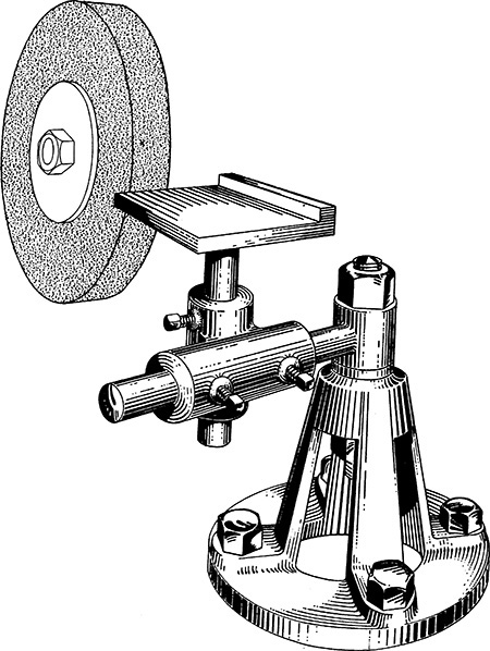
Examples of line shading on pictorial drawings often used in industrial sales literature are shown in Figures 23.21 and 23.22.

23.20 Computer Graphics
Perspective drawings, which provide pictorials most resembling photographs, are the most time-consuming types of pictorials to draw by hand. CAD programs produce either wireframe or solid perspective representations, with user selection of viewing distance, focal point, Z-axis convergence, and arc resolution scale. Historically, perspectives were used more in architectural applications than in engineering drawing. Increasingly widespread access to sophisticated CAD programs makes perspective drawing an alternative for pictorial representations of a variety of objects.
Chapter Summary
• The most realistic pictorial drawing is perspective.
• There are three types of perspective projection: one-point, two-point, and three-point perspective.
• In perspective projection, parallel edges converge to one or more vanishing points, which appear similar to how the human eye sees an object.
• Perspective projection can be produced by projection from two orthographic views (usually top and right side).
• Location and relationship between the vanishing points, the picture plane, and the object determine the appearance of the perspective view.
• In one-point perspective, the object is placed so that two of the three primary axes of the object are parallel to the picture plane.
• In two-point perspective, the object is placed so that only one of the three primary axes of the object is parallel to the picture plane.
• In three-point perspective, the object is placed so that none of the three primary axes of the object are parallel to the picture plane.
Review Questions
1. What is the primary advantage of a perspective projection?
2. Why is perspective projection rarely used in engineering?
3. What is the purpose of the picture plane?
4. What is the station point?
5. How does the distance between the station point and the ground line affect the final perspective drawing?
6. What is the relationship between the station point and the horizon?
7. What type of perspective is often used for rendering interior spaces in architectural drawings?
8. What tools are available to assist the drafter in creating perspective drawings on paper?
Chapter Exercises
Because many of the exercises in this chapter are of a general nature, they can also be solved on most computer graphics systems. If a system is available, the instructor may choose to assign specific problems to be completed by this method.
In addition to Exercises 23.1–23.6, many suitable problems for perspective are found among the axonometric and oblique problems at the end of Chapter 22.
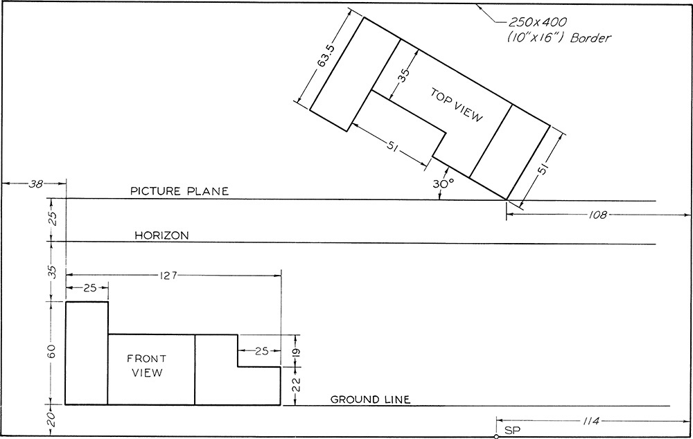
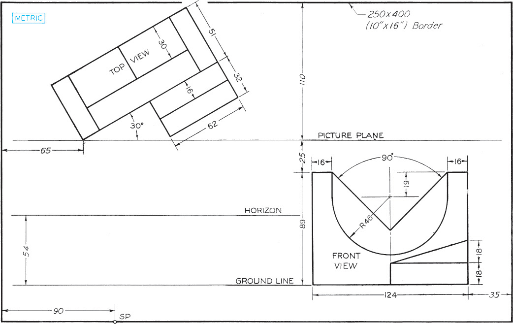
Exercise 23.1 Draw views in perspective on a size B or A3 sheet of paper, vellum, or film, with your name, date, class, and other information lettered below the border as specified by the instructor. Omit dimensions. (The dimensions given from the sheet border are to assist you in placing the views.)
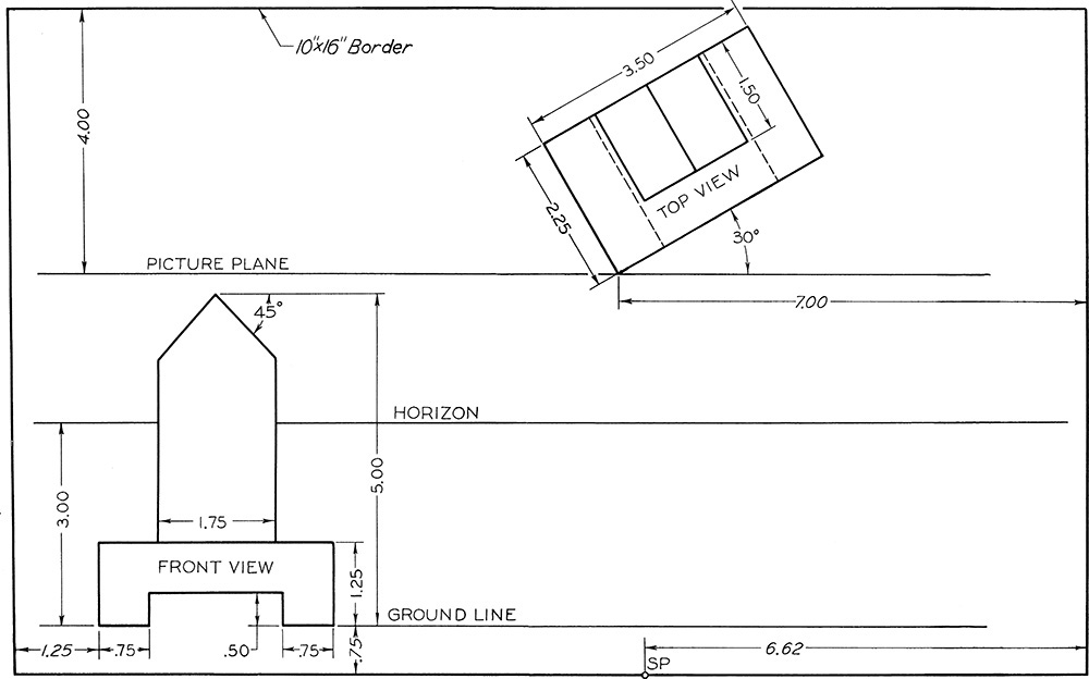
Exercise 23.2 Draw views in perspective on a size B or A3 sheet of paper, vellum, or film, with your name, date, class, and other information lettered below the border as specified by the instructor. Omit dimensions. (The dimensions given from the sheet border are to assist you in placing the views.)
Exercise 23.3 Draw views in perspective on a size B or A3 sheet of paper, vellum, or film, with your name, date, class, and other information lettered below the border as specified by the instructor. Omit dimensions. (The dimensions given from the sheet border are to assist you in placing the views.)
Exercise 23.4 Draw views in perspective on a size B or A3 sheet of paper, vellum, or film, with your name, date, class, and other information lettered below the border as specified by the instructor. Omit dimensions. (The dimensions given from the sheet border are to assist you in placing the views.)
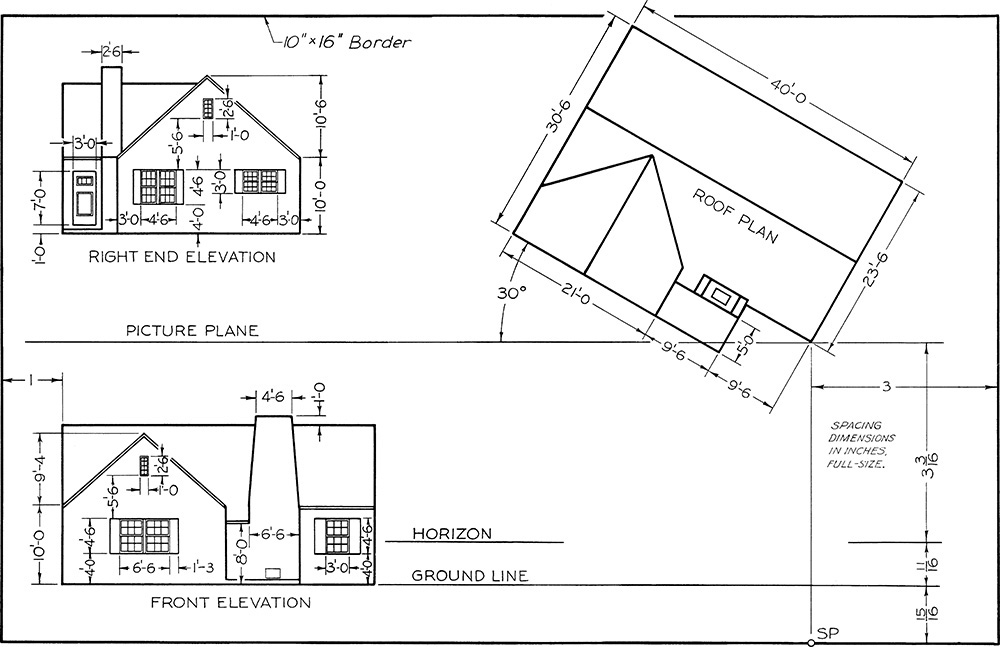
Exercise 23.5 Draw front elevation, plan, and perspective on size B or A3 paper. Determine the arrangement on the sheet to produce the most effective perspective in each case.
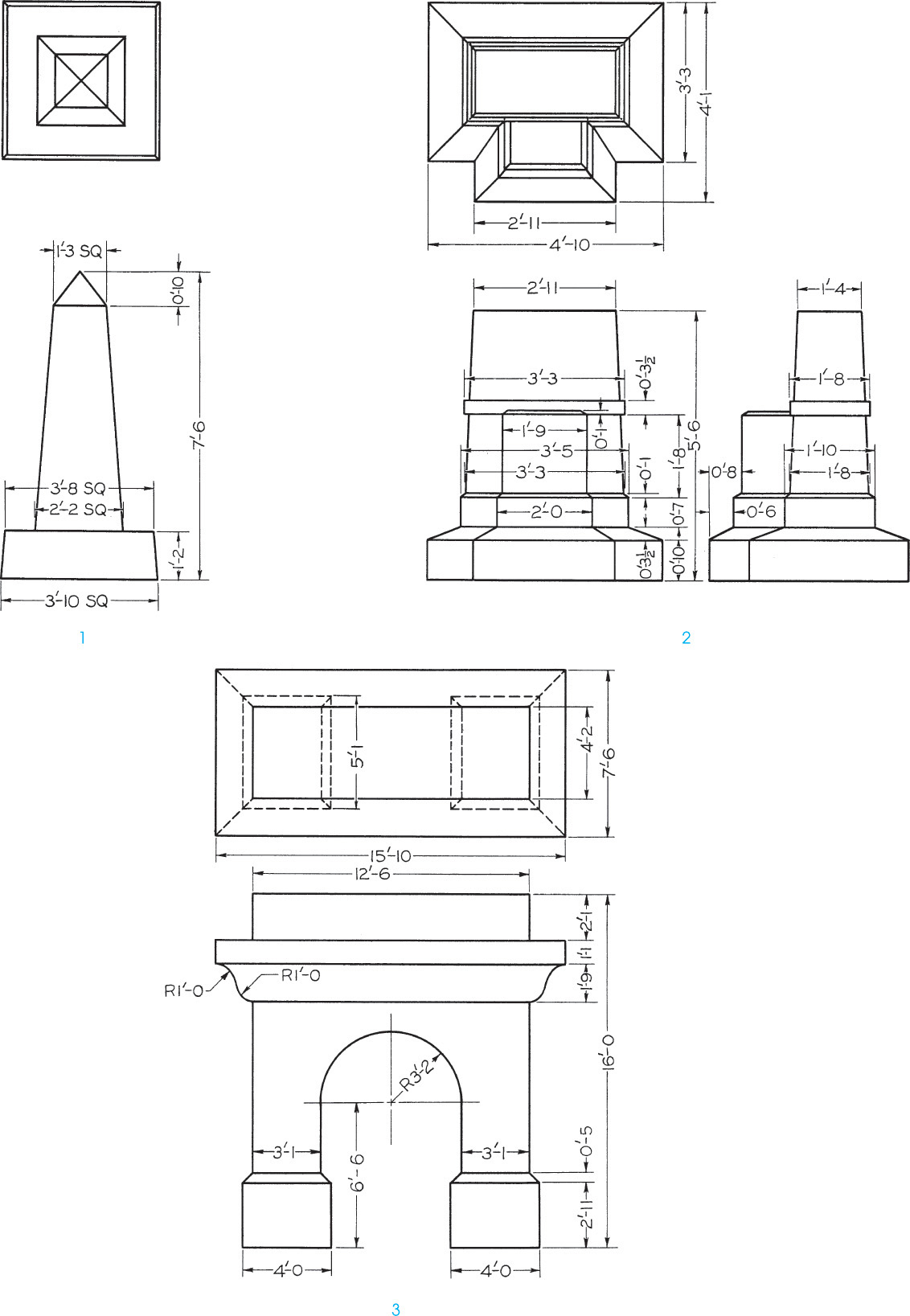
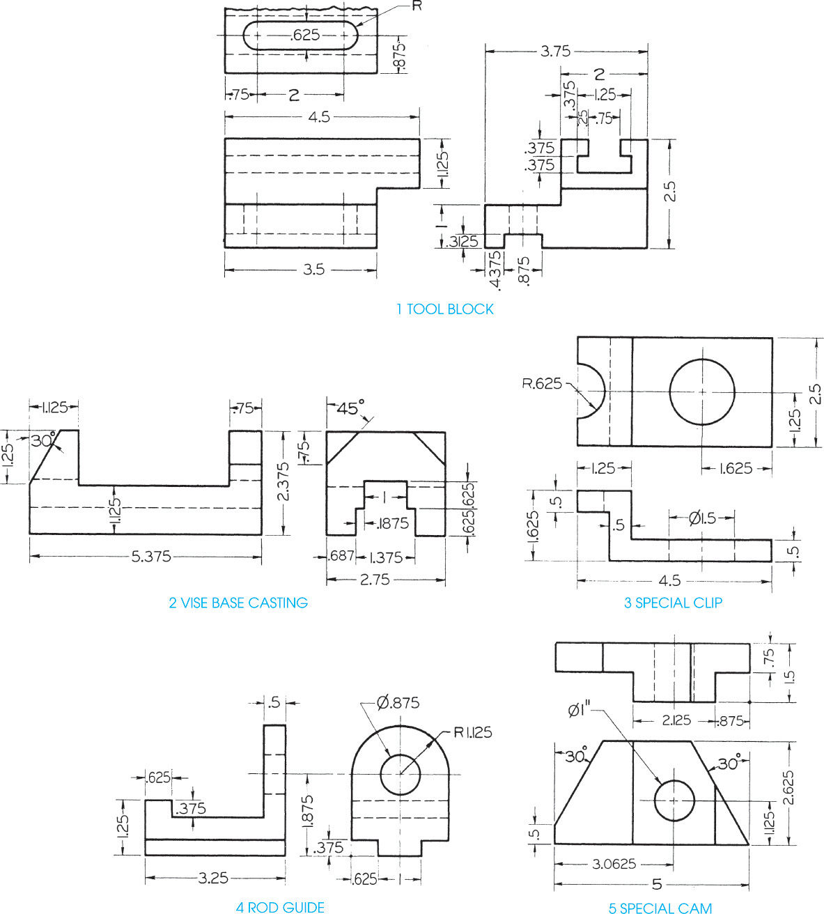
Exercise 23.6 Draw front elevation, plan, and perspective. Select both sheet size and scale.