
Chapter 13
Intermediate Graphics
There are a multitude of different graphical techniques used in games, which is why there are entire volumes and book series on the topic. This chapter explores a handful of intermediate graphics concepts: how to improve texture quality, rendering to textures, and a different method for lighting the scene, called deferred shading.
Improving Texture Quality
Recall from Chapter 5, “OpenGL,” that bilinear filtering can improve the visual quality of a texture as it gets larger on the screen. For example, suppose a wall has a texture on it. As the player gets closer to the wall, the size of the texture becomes larger onscreen. Without bilinear filtering, the texture will look pixelated. However, bilinear filtering makes the image look smoother (although slightly blurry).
Also recall from Chapter 5 that images are just 2D grids of pixels, and each of these “texture pixels” is called a texel. Another way to look at the enlargement effect is that as the wall texture becomes larger onscreen, the size of every texel becomes larger onscreen. In other words, the ratio between a texel from the texture and a pixel onscreen decreases.
For example, if every 1 texel corresponds to 2 pixels onscreen, then that ratio is 1:2. Texel density is this ratio between pixels onscreen and texels. Ideally, you want the texel density to be as close to 1:1 as possible. As the density decreases, the image quality decreases. Ultimately, the texture appears either too pixelated (if using nearest-neighbor filtering) or too blurry (if using bilinear filtering).
If the texel density becomes too high, this means that each pixel onscreen corresponds to multiple texels in the texture. For example, a 10:1 texel density means that every pixel onscreen corresponds to 10 texels. Ultimately, each of these pixels needs to choose a single color to display. This means that the texture will appear to have texels missing when viewed onscreen; this is called a sampling artifact. In graphics, the term artifact refers to a graphical glitch that’s a result of a graphics algorithm.
Figure 13.1 illustrates the different graphical artifacts caused by varying texel densities. Figure 13.1(a) shows a star texture at a texel density of roughly 1:1, meaning the texture appears onscreen with exactly the same ratio as the original image file. Figure 13.1(b) shows part of the star at a texel density of 1:5, which makes the edges appear blurry. Finally, Figure 13.1(c) shows the texture with a texel density of 5:1, which causes the edges of the star to disappear; to make the image easier to see, the figure illustrates it larger than the actual size.

Texture Sampling, Revisited
To understand why a high texel density causes texels to appear to be missing, we need to look more closely at how texture sampling works in general. Recall that textures use UV coordinates (also called texture coordinates) in the range of (0, 0) for the top-left corner and (1, 1) for the bottom-right corner. Suppose you have a texture that’s a 4×4 square of texels. In this case, the UV coordinate for the center of the top-left texel is (0.125, 0.125). Similarly, the exact center of the texture corresponds to the UV coordinate (0.5, 0.5), as in Figure 13.2(a).
Now suppose you have a texel density of 1:2, and you draw the region of the texture from (0, 0) to (0.5, 0.5). This means that the top one-fourth of the texture appears at two times the size onscreen. When drawing this in the fragment shader, each fragment (pixel) gets a UV coordinate corresponding to the center of the pixel. For example, the top-left pixel in Figure 13.2(b) is sampling from the texture with a UV coordinate of (0.0625, 0.0625). However, in the original image, no texel’s center directly corresponds to this coordinate. This is where a filtering algorithm comes in: It helps select what color to draw for these in-between UV coordinates.
In nearest-neighbor filtering, you simply select the texel whose center is the closest to that UV coordinate. So, because the top-left coordinate of (0.0625, 0.0625) is closest to the white texel at (0.125, 0.125), nearest-neighbor filtering selects white for that pixel. The result of this is that every texel is resized proportionally to the texel density, as in Figure 13.2(b). More plainly, in nearest-neighbor filtering, increasing the size of the texture onscreen increases the perceived size of each texel, making the image look pixelated.
In bilinear filtering, you find the four texel centers closest to a UV coordinate, and the sampled color at a UV coordinate is the weighted average between these four nearest texels. This yields a smoother transition as the image magnifies, though the image will appear blurry if magnified too much. Figure 13.2(c) illustrates bilinear filtering. Notice that there are fewer neighboring pixels with the same color, but instead the colors blend together.

Figure 13.2 (a) Original texture; texture at 2x magnification with (b) nearest-neighbor filtering and (c) bilinear filtering
To understand how to calculate the weighted average in bilinear filtering, remember that you can treat a color as a 3D value and interpolate between colors the same way you interpolate other values. You then decompose the bilinear interpolation into the two separate axes’ interpolations. Consider a point P that’s nearest the four texels A, B, C, and D, as in Figure 13.3. First, you compute the interpolation between the colors at A and B in the u direction and, similarly, the interpolation between C and D in the u direction. This yields colors at the two points R and S, shown in Figure 13.3. Finally, you interpolate the colors at R and S in the v direction, which yields the final color at P.

Given the texture coordinates for A, B, C, D, and P, you can calculate this bilinear interpolation with the following set of equations:

In these equations, uFactor determines the weighting in the u component direction, and vFactor determines the weighting in the v component direction. You then use these weightings to first calculate the colors at R and S and then, finally, the color at P.
These bilinear filtering calculations automatically occur on the graphics card if the texture has bilinear filtering enabled. And although this sounds like a lot of calculations to do for every fragment that samples the texture, modern graphics hardware can rapidly perform millions of such calculations per second.
As you’ve seen, magnifying the texture too much causes the image to appear either pixelated or blurry, depending on the technique used. The issue with reducing the size of the texture is that there aren’t enough texture samples to maintain all the information stored in the texture. Returning to the example texture, if you reduce the size of the image by a factor of two, the filtering loses details from the texture, as in Figure 13.4(b). You no longer see the border, as in the original image. This example is especially dramatic because you have only four pixels left after the size reduction.

Mipmapping
In mipmapping, rather than having a single source texture, you generate a series of additional textures, called mipmaps, that are at lower resolutions than the source texture. For example, if the source texture has a resolution of 256×256, you may generate mipmaps of 128×128, 64×64, and 32×32. Then, when it’s time to draw the texture onscreen, the graphics hardware can select the mipmap texture that yields a texel density closest to 1:1. While mipmapping doesn’t improve texture quality when you’re magnifying a texture to a resolution higher than the original resolution, it greatly improves the quality when you’re reducing the size of a texture.
The main reason for the quality improvement is that you generate the mipmap textures only once—at the time the texture is loaded. This means that you can use more expensive algorithms that generate high-quality mipmaps (such as using a box filter). Thus, sampling from these high-quality mipmaps with a texel density close to 1:1 will look much better than sampling from the original texture with some higher texel density, such as 4:1.
Figure 13.5 illustrates sample mipmaps for the star texture. The highest-resolution texture is the original texture at 256×256, and the remaining textures are auto-generated mipmaps. Note how even the smallest mipmap maintains the border of the texture, which was missing previously when you directly sampled from the 256×256 texture at a low texel density.

Much as texture sampling can use nearest-neighbor filtering or bilinear filtering, there are two different approaches to applying mipmaps. In nearest-neighbor mipmapping, you simply select the mipmap that gives the texel density closest to 1:1. Although this works well in many cases, in some instances (such as with a floor texture), it may cause banding at the borders where the mipmap texture (or mip level) changes. In trilinear filtering, you sample the two mip levels closest to a 1:1 texel density separately (with bilinear filtering), and the final color is a blend between these two samples. This is “trilinear” because it blends now in three dimensions—the UV coordinates of the texture samples as well as the mip-level blend.
Enabling mipmapping for a texture in OpenGL is straightforward. After loading a texture with the code from Chapter 5, you simply add a call to glGenerateMipmap:
glGenerateMipmap(GL_TEXTURE_2D);
This automatically generates appropriate mip levels, using a high-quality filtering algorithm.
When setting texture parameters, you can set both the minimization filter (what happens when the texture becomes smaller onscreen) and the magnification filter (what happens when the texture becomes larger onscreen). This is what the GL_TEXTURE_MIN_FILTER and GL_ TEXTURE_MAG_FILTER parameters reference.
After you’ve generated the mipmaps, you then change the texture parameter for the min filter to use mipmapping. To do trilinear filtering, you use these texture parameters:
glTexParameteri(GL_TEXTURE_2D, GL_TEXTURE_MIN_FILTER,
GL_LINEAR_MIPMAP_LINEAR);
glTexParameteri(GL_TEXTURE_2D, GL_TEXTURE_MAG_FILTER,
GL_LINEAR);
Note that you still use GL_LINEAR as the filtering function for magnification because mipmaps do not help with texel density lower than 1:1. To instead use nearest-neighbor mipmapping for minification, you would pass in GL_LINEAR_MIPMAP_NEAREST as the final parameter to the GL_TEXTURE_MIN_FILTER call.
Another advantage of mipmapping is that it improves the rendering performance due to the way that texture caching works. Much like a CPU cache, the graphics card has a cache for its memory. Small mip levels are very cache friendly, which means the overall rendering performance increases.
Anisotropic Filtering
Although mipmapping greatly reduces sampling artifacts in most instances, textures viewed at oblique angles relative to the camera will appear very blurry. This is noticeable especially with floor textures, as shown in Figure 13.6(b). Anisotropic filtering mitigates this by sampling additional points on the texture when it is viewed at an oblique angle. For example, 16x anisotropic filtering means that there are 16 different samples for the texel color.
The graphics hardware performs the anisotropic calculations, using a series of mathematical functions. This chapter does not cover these functions, but you can consult OpenGL Extensions Registry in the “Additional Reading” section at the end of this chapter for more information.
Although the newest specifications of OpenGL include anisotropic filtering as a default feature, anisotropic filtering is an extension in OpenGL 3.3. This means you should verify that the graphics hardware supports anisotropy before enabling the feature. For the most part, this is academic because every graphics card made in the past decade supports anisotropic filtering. But in general, it is a good idea to test whether an OpenGL extension is available before using said extension.
To turn on anisotropic filtering, you set the texture to use mipmapping and then add the following lines of code:
if (GLEW_EXT_texture_filter_anisotropic)
{
// Get the maximum anisotropy value
GLfloat largest;
glGetFloatv(GL_MAX_TEXTURE_MAX_ANISOTROPY_EXT, &largest);
// Enable it
glTexParameterf(GL_TEXTURE_2D, GL_TEXTURE_MAX_ANISOTROPY_EXT,
largest);
}
This code tests whether anisotropic filtering is available, and if it is, you ask OpenGL for the maximum anisotropy value. Then you set the texture parameter to use anisotropic filtering.
Figure 13.6 shows the ground from this chapter’s game project with different settings. Figure 13.6(a) shows the ground using only bilinear filtering; note how the ground has many sampling artifacts on the edges of the bricks. Figure 13.6(b) shows trilinear filtering enabled; this is an improvement, but the distant ground is blurry. Finally, Figure 13.6(c) shows both trilinear filtering and anisotropic filtering enabled, which yields the best visual quality of the three choices.
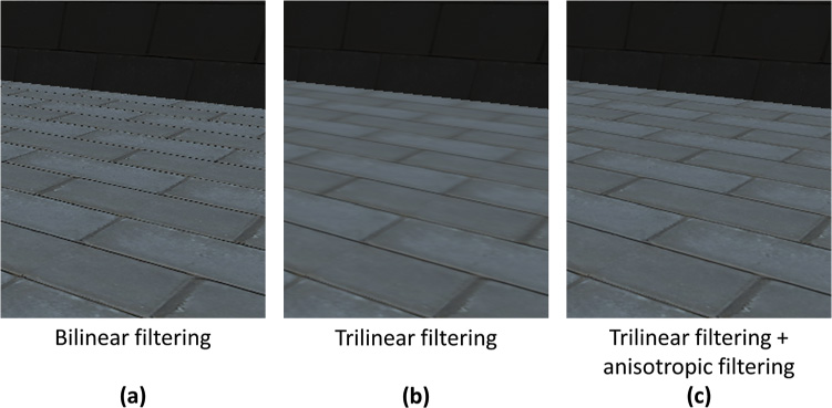
Figure 13.6 Viewing the ground with different filtering methods: (a) bilinear filtering, (b) trilinear filtering, and (c) trilinear and anisotropic filtering
Rendering to Textures
To this point, you’ve always drawn polygons directly to the color buffer. However, this color buffer isn’t special; it’s just a 2D image that you write colors to at specific coordinates. It turns out you can also draw the scene to any arbitrary texture, or render-to-texture. Although this may seem unnecessary, there are many reasons you may want to render to a texture.
For example, a racing game might have a car with a rearview mirror. If you want the mirror to look accurate, you might render the game world from the perspective of the rearview mirror to a texture and then draw the texture on the mirror in the scene. Furthermore, some graphical techniques use textures as temporary storage before computing the final output to the color buffer.
This section explores how to render to a texture and then display this texture on the screen. This will require some changes to the overall rendering code, which previously assumed that everything writes directly to the color buffer. You also need to add support for rendering the scene from the perspectives of different cameras.
note
For high-quality reflections, such as for a large mirror, you must render the scene from the perspective of the surface. However, if the game scene contains many surfaces that need low-quality reflections, rendering the scene from the perspective of each of these surfaces is too expensive. In this case, you can instead generate a single reflection map of the entire scene. Then, for every low-quality reflective surface, you sample from this reflection map to give the illusion of a reflection. Although the quality is significantly lower than when rendering from the perspective of the reflective surface, it is sufficient for surfaces that only need low-quality reflections.
This book does not cover how to implement reflection maps, but you can consult the “Additional Reading” section at the end of this chapter for further information on the topic.
Creating the Texture
To render to a texture, you first need to create a texture. You can add a new function to the Texture class to support creating a texture for rendering. The code for creating a texture, shown in Listing 13.1, is like the code for creating textures from Chapter 5. However, rather than assuming that you want an RGBA format (which will result in 8 bits per component and 32 bits per pixel), you use a parameter to specify the format. Second, the texture has no initial data, which is why the last parameter to glTexImage2D is nullptr. If this last parameter is nullptr, then the second and third-to-last parameters are ignored. Finally, you purposefully do not enable mipmapping or bilinear filtering on the texture. You want the sampled data from the texture to precisely match the actual output.
Listing 13.1 Creating a Texture for Rendering
void Texture::CreateForRendering(int width, int height,
unsigned int format)
{
mWidth = width;
mHeight = height;
// Create the texture id
glGenTextures(1, &mTextureID);
glBindTexture(GL_TEXTURE_2D, mTextureID);
// Set the image width/height with null initial data
glTexImage2D(GL_TEXTURE_2D, 0, format, mWidth, mHeight, 0, GL_RGB,
GL_FLOAT, nullptr);
// For a texture we'll render to, just use nearest neighbor
glTexParameteri(GL_TEXTURE_2D, GL_TEXTURE_MIN_FILTER, GL_NEAREST);
glTexParameteri(GL_TEXTURE_2D, GL_TEXTURE_MAG_FILTER, GL_NEAREST);
}
Creating a Framebuffer Object
Much the way that OpenGL uses a vertex array object to contain all information about vertices (including the vertex buffer, vertex format, and index buffer), a framebuffer object (FBO) contains all information about a framebuffer. The FBO includes any textures associated with the framebuffer, an associated depth buffer (if it exists), and other parameters. You can then select which framebuffer to use for rendering. OpenGL provides a default framebuffer object with ID 0, which is the framebuffer that you’ve been drawing to up to this point. However, you can also create additional framebuffers and switch to other framebuffers as needed.
For now, you will use a custom framebuffer object for a rearview mirror that you display in the HUD onscreen. First, you must add two new member variables to the Renderer class:
// Framebuffer object for the mirror
unsigned int mMirrorBuffer;
// Texture for the mirror
class Texture* mMirrorTexture;
You store the ID of the framebuffer object you create in mMirrorBuffer and the texture object associated with the framebuffer in mMirrorTexture.
Next, you need a function that creates and configures the mirror framebuffer object, as shown in Listing 13.2. Several steps are necessary here. First, glGenFrameBuffers creates the framebuffer object and stores the ID in mMirrorBuffer. The glBindFrameBuffer call then sets this framebuffer as active. The next several lines of CreateMirrorTexture create a depth buffer and attach it to the current framebuffer object. This way, when rendering for the mirror, you still have a depth buffer to ensure that further objects appear behind closer objects.
Then you create the mirror texture, with a width and height one-quarter the size of the screen. You don’t use the full screen size because you want the mirror to take up only part of the screen. You request a GL_RGB format for the texture because the mirror will contain the color output of the scene from the perspective of the mirror.
Next, the glFramebufferTexture call associates the mirror texture with the framebuffer object. Note how you specify GL_COLOR_ATTACHMENT0 as the second parameter. This says that the mirror texture corresponds to the first color output of the fragment shader. Right now, your fragment shader writes only one output, but as you’ll see later in this chapter, it’s possible to write multiple outputs from the fragment shader.
The glDrawBuffers call then says that for this framebuffer object, you want to be able to draw to the texture in the GL_COLOR_ATTACHMENT0 slot (which is the mirror texture). Finally, the glCheckFrameBuffer status call verifies that everything worked properly. If there was an issue, you delete the framebuffer object and mirror texture and return false.
Listing 13.2 Creating the Mirror Framebuffer
bool Renderer::CreateMirrorTarget()
{
int width = static_cast<int>(mScreenWidth) / 4;
int height = static_cast<int>(mScreenHeight) / 4;
// Generate a framebuffer for the mirror texture
glGenFramebuffers(1, &mMirrorBuffer);
glBindFramebuffer(GL_FRAMEBUFFER, mMirrorBuffer);
// Create the texture we'll use for rendering
mMirrorTexture = new Texture();
mMirrorTexture->CreateForRendering(width, height, GL_RGB);
// Add a depth buffer to this target
GLuint depthBuffer;
glGenRenderbuffers(1, &depthBuffer);
glBindRenderbuffer(GL_RENDERBUFFER, depthBuffer);
glRenderbufferStorage(GL_RENDERBUFFER, GL_DEPTH_COMPONENT, width, height);
glFramebufferRenderbuffer(GL_FRAMEBUFFER, GL_DEPTH_ATTACHMENT,
GL_RENDERBUFFER, depthBuffer);
// Attach mirror texture as the output target for the framebuffer
glFramebufferTexture(GL_FRAMEBUFFER, GL_COLOR_ATTACHMENT0,
mMirrorTexture->GetTextureID(), 0);
// Set the list of buffers to draw to for this framebuffer
GLenum drawBuffers[] = { GL_COLOR_ATTACHMENT0 };
glDrawBuffers(1, drawBuffers);
// Make sure everything worked
if (glCheckFramebufferStatus(GL_FRAMEBUFFER) != GL_FRAMEBUFFER_COMPLETE)
{
// If it didn't work, delete the framebuffer,
// unload/delete the texture and return false
glDeleteFramebuffers(1, &mMirrorBuffer);
mMirrorTexture->Unload();
delete mMirrorTexture;
mMirrorTexture = nullptr;
return false;
}
return true;
}
In Renderer::Initialize, you add a call to CreateMirrorTarget and verify that the function returns true. Similarly, in Renderer::Shutdown, you delete the mirror framebuffer and mirror textures (using the same code that runs if the glCheckFrameBuffer call says the framebuffer is not complete).
Rendering to a Framebuffer Object
To support a mirror, you need to render the 3D scene twice: once from the perspective of the mirror and once from the perspective of the normal camera. Each time you render the scene is a render pass. To assist with drawing the 3D scene multiple times, you can create a Draw3DScene function, the skeleton of which is in Listing 13.3.
The Draw3DScene function takes in the ID of the framebuffer, the view matrix, the projection matrix, and the scale of the viewport. The viewport size lets OpenGL know the actual size of the framebuffer target that it’s writing to. So, you need a viewport scale parameter here so that the normal framebuffer can use the full screen width and height, but the mirror can use its one-fourth size. You use the glViewport call to set the viewport to the correct size based on the screen width/height and the scale.
The code for drawing meshes is the same as in Chapter 6, “3D Graphics,” and the code for drawing skinned meshes is the same as in Chapter 12, “Skeletal Animation.” Other than the viewport code, the only other difference is that before drawing anything, the glBindFramebuffer call sets the active framebuffer to the requested one.
Listing 13.3 Renderer::Draw3DScene Helper Function
void Renderer::Draw3DScene(unsigned int framebuffer,
const Matrix4& view, const Matrix4& proj,
float viewportScale)
{
// Set the current framebuffer
glBindFramebuffer(GL_FRAMEBUFFER, framebuffer);
// Set viewport size based on scale
glViewport(0, 0,
static_cast<int>(mScreenWidth * viewPortScale),
static_cast<int>(mScreenHeight * viewPortScale)
);
// Clear color buffer/depth buffer
glClearColor(0.0f, 0.0f, 0.0f, 1.0f);
glClear(GL_COLOR_BUFFER_BIT | GL_DEPTH_BUFFER_BIT);
// Draw mesh components
// (Same code as Chapter 6)
// ...
// Draw any skinned meshes now
// (Same code as Chapter 12)
// ...
}
You then change the code in Renderer::Draw to call Draw3DScene twice, as in Listing 13.4. First, you draw using the mirror’s view and rendering to the mirror framebuffer, and then you draw using the normal camera’s view and rendering to the default framebuffer. Finally, you draw the sprites and UI screens using the code from Chapters 6 and 12.
Listing 13.4 Renderer::Draw Updated to Render Both Mirror and Default Passes
void Renderer::Draw()
{
// Draw to the mirror texture first (viewport scale of 0.25)
Draw3DScene(mMirrorBuffer, mMirrorView, mProjection, 0.25f);
// Now draw the normal 3D scene to the default framebuffer
Draw3DScene(0, mView, mProjection);
// Draw all sprite components
// (Same code as Chapter 6)
// ...
// Draw any UI screens
// (Same code as Chapter 12)
// ...
// Swap the buffers
SDL_GL_SwapWindow(mWindow);
}
Here, mMirrorView is a separate view matrix for the mirror. The specifics of the mirror view aren’t anything new. You can create a MirrorCamera class that uses a basic follow camera, as in Chapter 9, “Cameras.” However, the mirror camera is in front of the character, facing behind the character. This MirrorCamera then attaches to the player actor and updates mMirrorView.
Drawing the Mirror Texture in the HUD
Now that the drawing code is writing to the mirror texture, you can use it just like any other texture and draw it onscreen. Because the mirror in this case is just a HUD element, you can leverage the existing DrawTexture functionality in UIScreen.
However, drawing with the existing code results in a mirror that has a flipped y value from what is expected. This is because, internally, OpenGL places the UV origin at the bottom-left corner of the image instead of in the top-left corner (as is more typical). Luckily, this is easy enough to fix: When drawing the texture, you already create a scale matrix. If you negate the y-axis of this scale matrix, it will flip the texture in the y direction. To support this, you add a new flipY bool as an optional parameter to UIScreen::DrawTexture, as shown in Listing 13.5. You default flipY to false because the existing UI textures don’t need their y-axis flipped.
Listing 13.5 Adding a flipY Option to UIScreen::DrawTexture
void UIScreen::DrawTexture(class Shader* shader, class Texture* texture,
const Vector2& offset, float scale, bool flipY)
{
// Scale the quad by the width/height of texture
// and flip the y if we need to
float yScale = static_cast<float>(texture->GetHeight()) * scale;
if (flipY) { yScale *= -1.0f; }
Matrix4 scaleMat = Matrix4::CreateScale(
static_cast<float>(texture->GetWidth()) * scale,
yScale,
1.0f);
// Translate to position on screen
Matrix4 transMat = Matrix4::CreateTranslation(
Vector3(offset.x, offset.y, 0.0f));
// Set world transform
Matrix4 world = scaleMat * transMat;
shader->SetMatrixUniform("uWorldTransform", world);
// Set current texture
texture->SetActive();
// Draw quad
glDrawElements(GL_TRIANGLES, 6, GL_UNSIGNED_INT, nullptr);
}
Finally, you add two lines to HUD::Draw to display the mirror texture in the bottom-left corner of the screen, with a scale of 1.0 and flipY set to true:
Texture* mirror = mGame->GetRenderer()->GetMirrorTexture();
DrawTexture(shader, mirror, Vector2(-350.0f, -250.0f), 1.0f, true);
Figure 13.7 shows the mirror in action. Notice that the main view shows the normal perspective, which faces in the direction of the Feline Swordsman, but the mirror in the bottom left renders the scene in the opposite direction.

Deferred Shading
Recall that the Phong lighting implemented in Chapter 6 performs the lighting calculations for each fragment when drawing a mesh. The pseudocode for this type of lighting calculation is as follows:
foreach Mesh m in Scene
foreach Pixel p to draw from m
if p passes depth test
foreach Light li that effects p
color = Compute lighting equation(li, p)
Write color to framebuffer
This method of performing lighting calculations, called forward rendering, works well with a small number of lights. For example, the game currently has only one directional light, so forward rendering works perfectly fine. However, consider a game that takes place at night in a city. For such a game, a single directional light won’t yield a believable nightscape. Instead, you would want dozens of lights for street lights, car headlights, lights inside buildings, and so on. Unfortunately, forward rendering doesn’t scale well in this case. You need to compute lighting equations on the order of O(m · p · li), which means adding several more lights increases the amount of lighting calculations significantly.
An alternative approach is to create a series of textures, collectively called the G-buffer, to store information about the visible surfaces in the scene. This G-buffer might contain the diffuse color (albedo), specular power, and normals of visible surfaces in the scene. You then render the scene in two passes. First, you go through every mesh and render the properties of their surfaces to the G-buffer. Then, in the second pass, you loop through every light and compute the lighting equations based on these lights and what is in the G-buffer. The following pseudocode accomplishes this:
foreach Mesh m in Scene
foreach Pixel p1 to draw from m
if p passes depth test
Write surface properties of p1 to G-buffer
foreach Light li in the scene
foreach Pixel p2 affected by li
s = surface properties from the G-buffer at p2
color = Compute lighting equation (l, s)
Write color to framebuffer
Note how the complexity of this two-pass approach is O(m · p1 + li · p2). This means that you can support far more lights in the scene than with forward rendering. Because there are two passes, and the shading of the fragment onscreen doesn’t occur until the second pass, this technique is called deferred shading (or deferred rendering).
Implementing deferred shading requires several steps. First, you must set up a framebuffer object that supports multiple output textures. Then, you must create fragment shaders that write surface properties to the G-buffer. Next, you draw a quad that covers the entire screen and samples from the G-buffer to output the result of global lighting (such as directional and ambient light). Finally, you calculate the lighting for each non-global light (such as point lights or spotlights).
Creating a G-Buffer Class
Because the framebuffer object for the G-buffer is far more complex than the one for the mirror in the preceding section, it makes sense to encapsulate the FBO and all its associated textures into a new GBuffer class. Listing 13.6 shows the declaration of GBuffer. You declare an enum that defines the types of data stored in the different G-buffer textures. The G-buffer in this chapter stores the diffuse color, the normals, and the world position of each surface.
note
Storing the world position in the G-buffer makes your later calculations simpler—but at the expense of increased memory and rendering bandwidth usage.
It’s possible to reconstruct the world position at a pixel from the depth buffer and the view-projection matrix, which eliminates the need for the world position in the G-buffer. Consult Phil Djonov’s article in the “Additional Reading” section at the end of the chapter to learn how to do these calculations.
One surface property missing from this G-buffer is the specular power. This means you currently cannot calculate the specular component of the Phong reflection model; in Exercise 13.1 you will fix this.
In the member data for GBuffer, you store the framebuffer object ID as well as a vector of the textures that serve as render targets.
Listing 13.6 GBuffer Declaration
class GBuffer
{
public:
// Different types of data stored in the G-buffer
enum Type
{
EDiffuse = 0,
ENormal,
EWorldPos,
NUM_GBUFFER_TEXTURES
};
GBuffer();
~GBuffer();
// Create/destroy the G-buffer
bool Create(int width, int height);
void Destroy();
// Get the texture for a specific type of data
class Texture* GetTexture(Type type);
// Get the framebuffer object ID
unsigned int GetBufferID() const { return mBufferID; }
// Setup all the G-buffer textures for sampling
void SetTexturesActive();
private:
// Textures associated with G-buffer
std::vector<class Texture*> mTextures;
// Framebuffer object ID
unsigned int mBufferID;
};
For the member functions of GBuffer, most of the work occurs in the Create function, which creates a G-buffer of the specified width and height. Listing 13.7 gives the truncated code for this function. The Create function first creates a framebuffer object and adds a depth buffer target, as was done in Listing 13.2.
Listing 13.7 GBuffer::Create Implementation
bool GBuffer::Create(int width, int height)
{
// Create the framebuffer object and save in mBufferID
// ...
// Add a depth buffer to this target
// ...
// Create textures for each output in the G-buffer
for (int i = 0; i < NUM_GBUFFER_TEXTURES; i++)
{
Texture* tex = new Texture();
// We want three 32-bit float components for each texture
tex->CreateForRendering(width, height, GL_RGB32F);
mTextures.emplace_back(tex);
// Attach this texture to a color output
glFramebufferTexture(GL_FRAMEBUFFER, GL_COLOR_ATTACHMENT0 + i,
tex->GetTextureID(), 0);
}
// Create a vector of the color attachments
std::vector<GLenum> attachments;
for (int i = 0; i < NUM_GBUFFER_TEXTURES; i++)
{
attachments.emplace_back(GL_COLOR_ATTACHMENT0 + i);
}
// Set the list of buffers to draw to
glDrawBuffers(static_cast<GLsizei>(attachments.size()),
attachments.data());
// Make sure everything worked
if (glCheckFramebufferStatus(GL_FRAMEBUFFER) !=
GL_FRAMEBUFFER_COMPLETE)
{
Destroy();
return false;
}
return true;
}
Next, you loop over each type of texture desired in the G-buffer and create one Texture instance for each type of data (because they are separate render targets). Note that you request the GL_RGB32F format for each texture. This means there are three components per texel, and each of these components is a 32-bit single-precision floating-point value. You then attach each texture to a corresponding color attachment slot with the glFramebufferTexture call. The code takes advantage of the fact that the OpenGL definitions for the color attachments are consecutive numbers.
note
Although GL_RGB32F yields a lot of precision for the values in the G-buffer, the trade-off is that the G-buffer takes up a significant amount of graphics memory. Three GL_RGB32F textures at a resolution of 1024×768 (your screen resolution) takes up 27 MB of memory on the GPU. To reduce memory usage, many games instead use GL_RGB16F (three half-precision floats), which would cut the memory usage in half.
You could further optimize the memory usage with other tricks. For example, because a normal is unit length, given the x and y components and the sign of the z component, you can solve for the z component. This means you could store the normals in GL_RG16F format (two half-precision floats) and later derive the z component. In the interest of simplicity, this chapter does not implement these optimizations, but you should know that many commercial games use such tricks.
You then create a vector of all the different color attachments and call glDrawBuffers to set the texture attachments for the G-buffer. Finally, you validate that creating the G-buffer succeeds. If it doesn’t, the Destroy function deletes all associated textures and destroys the framebuffer object.
Next, you add a GBuffer pointer to the member data of Renderer:
class GBuffer* mGBuffer;
Then in Renderer::Initialize, you create the GBuffer object and set it to the width/height of the screen:
mGBuffer = new GBuffer();
int width = static_cast<int>(mScreenWidth);
int height = static_cast<int>(mScreenHeight);
if (!mGBuffer->Create(width, height))
{
SDL_Log("Failed to create G-buffer.");
return false;
}
In Renderer::Shutdown, you add code that calls the Destroy member function on mGBuffer.
Writing to the G-buffer
Now that you have a G-buffer, you need to write data into it. Recall that mesh rendering currently uses the Phong fragment shader to write final (fully lit) colors to the default framebuffer. However, this is antithetical to the approach of deferred shading. You need to create a new fragment shader that writes surface properties into the G-buffer.
Another difference is that every previous fragment shader wrote only a single output value. However, fragment shaders can have multiple output values, or multiple render targets. This means that writing to each texture in the G-buffer is just a matter of writing to each of the correct outputs. In fact, the GLSL code for the main function of the fragment shader is relatively simple compared to the code for fragment shaders you’ve seen earlier in this book. You sample the diffuse color from the texture and simply pass along the normal and world position directly to the G-buffer.
Listing 13.8 gives the full GLSL code for GBufferWrite.frag. Note that you declare three different out values for the three different G-buffer textures. You also specify layout locations for each of the outputs; these numbers correspond to the color attachment indices specified when creating the G-buffer.
Listing 13.8 GBufferWrite.frag Shader
#version 330
// Inputs from vertex shader
in vec2 fragTexCoord; // Tex coord
in vec3 fragNormal; // Normal (in world space)
in vec3 fragWorldPos; // Position (in world space)
// This corresponds to the outputs to the G-buffer
layout(location = 0) out vec3 outDiffuse;
layout(location = 1) out vec3 outNormal;
layout(location = 2) out vec3 outWorldPos;
// Diffuse texture sampler
uniform sampler2D uTexture;
void main()
{
// Diffuse color is from texture
outDiffuse = texture(uTexture, fragTexCoord).xyz;
// Pass normal/world position directly along
outNormal = fragNormal;
outWorldPos = fragWorldPos;
}
You then change the shader loading code for the mMeshShader and mSkinnedShader to use GBufferWrite.frag as the fragment shader, instead of the previous Phong.frag.
Finally, in Renderer::Draw, you remove the call to Draw3DScene, which draws to the default framebuffer. You instead want to draw to the G-buffer:
Draw3DScene(mGBuffer->GetBufferID(), mView, mProjection, 1.0f, false);
The last Boolean parameter is new; it specifies that Draw3DScene should not set any lighting constants on the mesh shaders. This makes sense because the GBufferWrite.frag shader doesn’t have any lighting constants to set in the first place!
Running the game at this point would yield an entirely black window other than the UI elements. This is because although you’re writing surface properties to the G-buffer, you aren’t drawing anything to the default framebuffer based on these surface properties. However, by using a graphics debugger such as RenderDoc (see the sidebar “Graphics Debuggers”), you can view the output to the different textures in the G-buffer. Figure 13.8 shows a visualization of the output to the different components of the G-buffer, including the depth buffer.

Global Lighting
Now that the game is writing surface properties to the G-buffer, the next step is to use these properties to display a fully lit scene. This section focuses on global lights such as the ambient and a global directional light. The basic premise is to draw a quad the size of the screen to the default framebuffer. For each fragment in this quad, you sample surface properties from the G-buffer. Then, using these surface properties, you can compute the same Phong lighting equations from Chapter 6 to light the fragment.
First, you create a vertex and fragment shader in GLSL for global lighting from the G-buffer. Because you’re ultimately drawing a quad to the screen, the vertex shader is identical to the sprite vertex shader from Chapter 5. The fragment shader, shown in Listing 13.9, has some differences from the Phong fragment shader. First, the only input from the vertex shader is the texture coordinates. This is because the normal and world positions at the fragment are in the G-buffer. Next, you add three sampler2D uniforms for the three different textures in the G-buffer (diffuse color, normal, and world position). In the main function for the fragment shader, you sample the diffuse color, normal, and world position from the G-buffer textures. This, combined with the directional light uniforms (as in Chapter 6), gives all the information needed to light the fragment with the ambient and diffuse components of the Phong reflection model. You cannot calculate the specular component because this depends on the specular power of each surface, and you currently do not store the specular information in the G-buffer. (In Exercise 13.1 you explore adding the specular component.)
After calculating the Phong ambient and diffuse component, you multiply the diffuse color of the surface (from the G-buffer) to compute the final color at the pixel.
Listing 13.9 GBufferGlobal.frag Shader
#version 330
// Inputs from vertex shader
in vec2 fragTexCoord; // Tex coord
layout(location = 0) out vec4 outColor;
// Different textures from G-buffer
uniform sampler2D uGDiffuse;
uniform sampler2D uGNormal;
uniform sampler2D uGWorldPos;
// Lighting uniforms (as in Chapter 6)
// ...
void main()
{
// Sample diffuse color, normal, world position from G-buffer
vec3 gbufferDiffuse = texture(uGDiffuse, fragTexCoord).xyz;
vec3 gbufferNorm = texture(uGNormal, fragTexCoord).xyz;
vec3 gbufferWorldPos = texture(uGWorldPos, fragTexCoord).xyz;
// Calculate Phong lighting (as in Chapter 6, minus specular)
// ...
// Final color is diffuse color times phong light
outColor = vec4(gbufferDiffuse * Phong, 1.0);
}
With the global lighting vertex and fragment shader code written, the next step is to load these shaders in the Renderer class. You create a Shader* member variable called mGGlobalShader and instantiate it in the LoadShader function. In this code, shown in Listing 13.10, you first load the vertex and fragment shader files. Then, you set some of the uniforms for the shader.
The SetIntUniform calls associate each of the three sampler2D uniforms in the fragment shader with a specific texture index. The first SetMatrixUniform call sets the view-projection matrix to be identical to the sprite view-projection matrix (because you’re drawing a quad). The second call sets the world transform to scale the quad to the entire screen and invert the y-axis (to solve the inverted y problem, as when drawing the mirror texture to the screen).
Listing 13.10 Loading the G-buffer Global Lighting Shader
mGGlobalShader = new Shader();
if (!mGGlobalShader->Load("Shaders/GBufferGlobal.vert",
"Shaders/GBufferGlobal.frag"))
{
return false;
}
// For the GBuffer, we need to associate each sampler with an index
mGGlobalShader->SetActive();
mGGlobalShader->SetIntUniform("uGDiffuse", 0);
mGGlobalShader->SetIntUniform("uGNormal", 1);
mGGlobalShader->SetIntUniform("uGWorldPos", 2);
// The view projection is just the sprite one
mGGlobalShader->SetMatrixUniform("uViewProj", spriteViewProj);
// The world transform scales to the screen and flips y
Matrix4 gbufferWorld = Matrix4::CreateScale(mScreenWidth,
-mScreenHeight, 1.0f);
mGGlobalShader->SetMatrixUniform("uWorldTransform", gbufferWorld);
Next, you add a function to the GBuffer class that binds each texture in the G-buffer to a corresponding texture index:
void GBuffer::SetTexturesActive()
{
for (int i = 0; i < NUM_GBUFFER_TEXTURES; i++)
{
mTextures[i]->SetActive(i);
}
}
Here, the SetActive function called on each texture takes in an index, which corresponds to the indices set on the sampler2D uniforms in GLSL.
The final step is to add a function to Renderer that draws the G-buffer quad using the global lighting shader. You create a new DrawFromGBuffer function, as shown in Listing 13.11. Because the first step in Renderer::Draw is now to draw the scene to the G-buffer, DrawFromGBuffer is now the first code that draws to the default framebuffer. You need to disable depth testing for the quad, as you don’t want it to affect the depth buffer. You then set the G-buffer shader and sprite quad vertices as active and call the SetTexturesActive function to activate all the G-buffer textures. You then use the SetLightUniforms function, created in Chapter 6, to set all the directional light uniforms in the G-buffer shader. Finally, you draw the quad, which invokes your G-buffer fragment shader for every fragment onscreen.
Listing 13.11 Renderer::DrawFromGBuffer Implementation
void Renderer::DrawFromGBuffer()
{
// Disable depth testing for the global lighting pass
glDisable(GL_DEPTH_TEST);
// Activate global G-buffer shader
mGGlobalShader->SetActive();
// Activate sprite verts quad
mSpriteVerts->SetActive();
// Set the G-buffer textures to sample
mGBuffer->SetTexturesActive();
// Set the lighting uniforms
SetLightUniforms(mGGlobalShader, mView);
// Draw the triangles for the quad
glDrawElements(GL_TRIANGLES, 6, GL_UNSIGNED_INT, nullptr);
}
Next, you change the code at the start of Renderer::Draw to first draw the 3D scene to the G-buffer, change the framebuffer to the default and finally call DrawFromGBuffer. After this, you render the sprites and UI screens as before:
// Draw the 3D scene to the G-buffer
Draw3DScene(mGBuffer->GetBufferID(), mView, mProjection, false);
// Set the framebuffer back to zero (screen's framebuffer)
glBindFramebuffer(GL_FRAMEBUFFER, 0);
// Draw from the GBuffer
DrawFromGBuffer();
// Draw Sprite/UI as before
// ...
With the global lighting shader code in place, the rendering code now draws the entire scene fully lit once again. Figure 13.9 shows the scene output. Note that because you are no longer calculating the specular component of the Phong lighting equation, the scene looks darker than before—even with a slightly higher ambient light value than you had previously. However, you can still see the entire scene, and other than the darkness, it looks like the forward-rendered scene. Also, note that the mirror still works properly, even though you still use forward rendering for the mirror (and because of the higher ambient light, the mirror looks brighter than before).

Adding Point Lights
Recall that one of the main reasons to use deferred shading is that it scales very well as the number of lights in the scene increases. This section discusses how to add support for many non-global lights.
Suppose the game has 100 different point lights. You could create a uniform array in the shader that stores all the information about these point lights, including position, color, radius, and so on. Then in the GBufferGlobal.frag shader code, you could loop over these point lights. Using the G-buffer sampled world position, you could figure out whether a fragment is within range of a point light and, if so, compute the Phong equation for this.
Although this approach could work, there are some issues with it. You need to test every fragment against every point light, even for lights that are nowhere near the fragment. This means a lot of conditional checks in the shader code, which is expensive.
The solution to these problems is to instead use light geometry, or meshes that represent the lights. Because a point light has a radius, its corresponding light geometry is a sphere placed in the world. Drawing this sphere will then trigger a fragment shader call for every fragment the sphere touches. Using the world position information from the G-buffer, you can compute the intensity of the light to the fragment.
Adding a PointLightComponent Class
For point lights, you can create a component so that it’s easy to attach to any actor to move the light. First, you declare the PointLightComponent class, as shown in Listing 13.12. For simplicity, you make its member variables public. The diffuse color is simply the diffuse color of the point light. The inner and outer radius variables determine the area of influence of the point light. The outer radius is the maximum distance from which the point light affects an object. The inner radius is the radius at which the point light applies its full intensity of light. Anything inside the inner radius has the full diffuse color, while the color intensity falls off when approaching the outer radius. The point light doesn’t affect anything past the outer radius.
Listing 13.12 PointLightComponent Declaration
class PointLightComponent
{
public:
PointLightComponent(class Actor* owner);
~PointLightComponent();
// Draw this point light as geometry
void Draw(class Shader* shader, class Mesh* mesh);
// Diffuse color
Vector3 mDiffuseColor;
// Radius of light
float mInnerRadius;
float mOuterRadius;
};
You then add a vector of PointLightComponent pointers to the Renderer class called mPointLights. The constructor for PointLightComponent adds the light to mPointLights, and the destructor removes the light from the vector.
Point Light Fragment Shader
The next step is to create a GBufferPointLight.frag fragment shader file. As in the GBufferGlobal.frag shader, you need to declare three different sampler2D uniforms for the three different G-buffer textures. Unlike with the global lighting shader, however, you need to store information about a specific point light. You declare a PointLight struct and add a uPointLight uniform for this. You also add a uniform, uScreenDimensions, that stores the width/height of the screen:
// Additional uniforms for GBufferPointLight.frag
struct PointLight
{
// Position of light
vec3 mWorldPos;
// Diffuse color
vec3 mDiffuseColor;
// Radius of the light
float mInnerRadius;
float mOuterRadius;
};
uniform PointLight uPointLight;
// Stores width/height of screen
uniform vec2 uScreenDimensions;
The shader’s main function, given in Listing 13.13, is different from the global light shader in several ways. With the quad you drew for global lighting, you could simply use the texture coordinates of the quad to sample correctly into the G-buffer. However, using the texture coordinates from the point light’s sphere mesh would not yield a correct UV coordinate to sample into the G-buffer. Instead, you can use gl_FragCoord, which is a built-in GLSL variable that contains the position in screen space of the fragment. In this instance, you only care about the x and y coordinates. However, because UV coordinates are in the range [0, 1], you need to divide the screen space coordinates by the dimensions of the screen. The division operator in this case is a component-wise division.
Once you have the correct UV coordinates, you use them to sample the diffuse, normal, and world positions from the G-buffer. Next, you compute the N and L vectors, much as in the previous Phong fragment shader.
Listing 13.13 GBufferPointLight.frag Main Function
void main()
{
// Calculate the coordinate to sample into the G-buffer
vec2 gbufferCoord = gl_FragCoord.xy / uScreenDimensions;
// Sample from G-buffer
vec3 gbufferDiffuse = texture(uGDiffuse, gbufferCoord).xyz;
vec3 gbufferNorm = texture(uGNormal, gbufferCoord).xyz;
vec3 gbufferWorldPos = texture(uGWorldPos, gbufferCoord).xyz;
// Calculate normal and vector from surface to light
vec3 N = normalize(gbufferNorm);
vec3 L = normalize(uPointLight.mWorldPos - gbufferWorldPos);
// Compute Phong diffuse component for the light
vec3 Phong = vec3(0.0, 0.0, 0.0);
float NdotL = dot(N, L);
if (NdotL > 0)
{
// Get the distance between the light and the world pos
float dist = distance(uPointLight.mWorldPos, gbufferWorldPos);
// Use smoothstep to compute value in range [0,1]
// between inner/outer radius
float intensity = smoothstep(uPointLight.mInnerRadius,
uPointLight.mOuterRadius, dist);
// The diffuse color of the light depends on intensity
vec3 DiffuseColor = mix(uPointLight.mDiffuseColor,
vec3(0.0, 0.0, 0.0), intensity);
Phong = DiffuseColor * NdotL;
}
// Final color is texture color times phong light
outColor = vec4(gbufferDiffuse * Phong, 1.0);
}
However, when computing the diffuse color, you first calculate the distance between the point light’s center and the fragment’s world position. Then, the smoothstep function calculates a value in the range [0, 1]. The function returns 0 for distances less than or equal to the inner radius and 1 for distances greater than or equal to the outer radius. Distances in between yield some value in between. The smoothstep function uses a Hermite function (a type of polynomial) to calculate this in-between value. The resulting value corresponds to an intensity of the diffuse light; the value 0 means full intensity because the fragment is within the inner radius, whereas the value 1 means the point light should not affect the fragment.
You then compute the applied DiffuseColor based on the intensity value. Here, the mix function performs a linear interpolation between the point light’s diffuse color and pure black. Remember that you do not calculate the specular component of the Phong reflection here because you currently do not have access to the specular power in the G-buffer.
It’s important to understand that because point light rendering occurs after the global light G-buffer calculations, each fragment in the framebuffer already has a color. You don’t want the point light shader to overwrite the colors that are already there. For example, if a fragment’s world position says it’s out of range of the point light, the shader will return black. If you just set the fragment to black, you lose all the color that was already there from the global lighting pass.
Instead, you want to add the output of the point light shader to whatever color is already there. Adding black to the color does not change any of the RGB values, which means it preserves the existing light. On the other hand, if you add a green value, that makes the fragment greener. Adding the output color to the existing color doesn’t require any changes to the fragment shader code itself; instead, you can do this on the C++ side of things.
Drawing Point Lights
You need to add some glue code to Renderer and PointLightComponent before you can draw the point lights in DrawFromGBuffer. First, you add a new shader member variable called mGPointLightShader. You then load this shader in LoadShaders. For the vertex shader, you use the BasicMesh.vert shader from Chapter 6 because the point light’s sphere mesh doesn’t need any special behavior. For the fragment shader, you use the GBufferPointLight.frag shader.
As with the global lighting shader, you need to set the uniforms for the different samplers to bind them to specific G-buffer textures. You also set the uScreenDimensions uniform to the width and height of the screen.
You also add a mPointLightMesh member variable that simply points to the mesh you want to use for the point lights. You load the mesh when initializing the Renderer and save it in the variable; the mesh in question is a sphere.
Now you add additional code to DrawFromGBuffer, shown in Listing 13.14. This code goes after all the code that drew the full-screen quad that applied global lighting. The first part of this code copies the depth buffer from the G-buffer to the default framebuffer’s depth buffer. Because you’re drawing the 3D scene to the G-buffer, its depth buffer contains the actual depth information for every fragment. Because you want to depth test the point light spheres, you need to copy over this information to the default depth buffer.
Listing 13.14 Drawing Point Lights in Renderer::DrawFromGBuffer
// Copy depth buffer from G-buffer to default framebuffer
glBindFramebuffer(GL_READ_FRAMEBUFFER, mGBuffer->GetBufferID());
int width = static_cast<int>(mScreenWidth);
int height = static_cast<int>(mScreenHeight);
glBlitFramebuffer(0, 0, width, height,
0, 0, width, height,
GL_DEPTH_BUFFER_BIT, GL_NEAREST);
// Enable depth test, but disable writes to depth buffer
glEnable(GL_DEPTH_TEST);
glDepthMask(GL_FALSE);
// Set the point light shader and mesh as active
mGPointLightShader->SetActive();
mPointLightMesh->GetVertexArray()->SetActive();
// Set the view-projection matrix
mGPointLightShader->SetMatrixUniform("uViewProj",
mView * mProjection);
// Set the G-buffer textures for sampling
mGBuffer->SetTexturesActive();
// The point light color should add to existing color
glEnable(GL_BLEND);
glBlendFunc(GL_ONE, GL_ONE);
// Draw the point lights
for (PointLightComponent* p : mPointLights)
{
p->Draw(mGPointLightShader, mPointLightMesh);
}
Next, you reenable the depth test (because you disabled it when drawing the full-screen quad for the global lighting), but you disable the depth mask. This means that when you try to draw fragments for each point light’s sphere, they need to pass the depth test, but these fragments do not write new depth values to the depth buffer. This ensures that the point light sphere meshes do not interfere with the existing depth buffer values. Because you’re disabling depth buffer writes here, you add a corresponding call to the beginning of Draw3DScene that reenables writes to the depth buffer. (Otherwise, you can’t clear the depth buffer!)
Then you activate the shader for the point lights as well as the corresponding point light mesh. You need to set the view-projection matrix just as for any other object rendered in the world to make sure the point light has the correct location onscreen. You also need to bind the G-buffer textures to their respective slots.
Because you want to add to the colors already in the color buffer, you enable blending. The blend function with GL_ONE as both parameters says that you just want to directly add the two colors, without considering the alpha values or any other parameters.
Finally, you loop over all the point lights and call the Draw function on each point light. The code for PointLightComponent::Draw, shown in Listing 13.15, doesn’t look that much different from the code for drawing any other mesh. For the world transform matrix, you need to scale based on the outer radius of the light. You divide by the radius of the mesh because the point light mesh does not have a unit radius. The translation is just based on the position of the light, which comes from the owning actor.
Furthermore, you need to set the different uniforms for this specific point light, which isn’t different from how you’ve set the uniforms before. Finally, the glDrawElements call draws the light geometry for the point light, which is your sphere mesh. You don’t need to set the vertex array as active because the Renderer does this before calling Draw.
Once you draw all the point light meshes, for every fragment you calculate the contribution of the point light to the color of the fragment. You then add this additional light color to the already existing color from the global lighting pass.
Listing 13.15 PointLightComponent::Draw Implementation
void PointLightComponent::Draw(Shader* shader, Mesh* mesh)
{
// Scale world transform to the outer radius (divided by
// the mesh radius) and positioned to the world position
Matrix4 scale = Matrix4::CreateScale(mOwner->GetScale() *
mOuterRadius / mesh->GetRadius());
Matrix4 trans = Matrix4::CreateTranslation(mOwner->GetPosition());
Matrix4 worldTransform = scale * trans;
shader->SetMatrixUniform("uWorldTransform", worldTransform);
// Set point light shader constants
shader->SetVectorUniform("uPointLight.mWorldPos", mOwner->GetPosition());
shader->SetVectorUniform("uPointLight.mDiffuseColor", mDiffuseColor);
shader->SetFloatUniform("uPointLight.mInnerRadius", mInnerRadius);
shader->SetFloatUniform("uPointLight.mOuterRadius", mOuterRadius);
// Draw the sphere
glDrawElements(GL_TRIANGLES, mesh->GetVertexArray()->GetNumIndices(),
GL_UNSIGNED_INT, nullptr);
}
To demonstrate the point light rendering, this chapter’s game project creates several point lights with different colors along the floor. Figure 13.10 illustrates these point lights, powered by deferred shading.

Improvements and Issues
Although deferred shading is a very powerful rendering technique used by many modern games, it isn’t perfect. One problem is that it can’t handle partially transparent objects such as windows. Because the G-buffer can only store a single surface’s properties, drawing such an object into the G-buffer would overwrite the objects behind it. The solution for this case is to draw transparent objects in a separate pass after drawing the rest of the scene.
Also, for some types of games, the overhead of setting up the G-buffer and rendering to multiple targets is not worth it. If a game takes place largely during the day or has a very small number of lights, the cost of the deferred shading setup every frame might be higher than the cost of a forward-rendering approach. Many virtual-reality games, which need a very high frame rate, use forward rendering for this reason.
Another issue is that the light geometry has many edge cases to consider and fix. For example, if the point light sphere partially intersects with a wall, the point light will affect both sides of the wall in the current approach. Also, if you create a very big point light but place the camera inside the light, you don’t see the effect of that light. To fix these light geometry issues, you need to use a stencil buffer, which is a different type of output buffer.
Game Project
This chapter’s game project provides the full implementation of deferred shading. In addition, it uses both mipmapping and anisotropic aliasing to improve texture quality. The project includes the mirror texture that’s forward rendered. The code is available in the book’s GitHub repository, in the Chapter13 directory. Open Chapter13-windows.sln in Windows and Chapter13-mac.xcodeproj on Mac.
There are no changes to the controls or character from the previous chapter. The player still uses the WASD keys to move the character around. To demonstrate the point lights, several point lights are provided in Game::LoadData.
Summary
This chapter covers a handful of intermediate graphics techniques. First, it looks at how texture filtering works—both nearest-neighbor filtering and bilinear filtering. Mipmapping can reduce sampling artifacts when reducing the size of textures because it generates several lower-resolution textures. However, for oblique surfaces, mipmapping may appear blurry. In this case, anisotropic filtering improves the quality of the textures.
Another powerful technique is rendering the scene to textures. OpenGL allows creation of arbitrary framebuffer objects associated with textures. Then, you can choose to draw the 3D scene to this texture. One use of this technique is to draw a high-quality reflection, such as for a mirror.
Finally, this chapter explores deferred shading, which is a two-pass approach to lighting. In the first pass, you write the object’s surface properties, such as diffuse color, normals, and world position, into a G-buffer. In the second pass, you read from the G-buffer to calculate lighting equations. For lights with limited ranges, such as point lights, you render lighting geometry to ensure that the light affects only the fragments in range. Deferred shading is an excellent approach when there are many lights in the scene, though there are some issues, such as the inability to handle partially transparent objects.
Additional Reading
As mentioned in Chapter 6, Real-Time Rendering by Thomas Akenine-Moller et al. is the go-to book when it comes to rendering techniques and games. Jason Zink et al. give a good overview of many techniques, including deferred shading, even though the book focuses on Direct3D 11 instead of OpenGL. Matt Pharr et al. cover physically based rendering, which is a newer technique games use to achieve more realistic lighting. Wolfgang Engel’s books are always on the cutting edge of what graphics programmers in the video game industry are using. Phil Djonov discusses how to eliminate the need for the world position in the G-buffer. Finally, sometimes to understand how various OpenGL extensions work, you need to read the official registry.
Akenine-Moller, Thomas, Eric Haines, and Naty Hoffman. Real-Time Rendering, 3rd edition. Natick: A K Peters, 2008.
Djonov, Phil. “Deferred Shading Tricks.” Shiny Pixels. Accessed November 26, 2017. http://vec3.ca/code/graphics/deferred-shading-tricks/.
Engel, Wolfgang, ed. GPU Zen: Advanced Rendering Techniques. Encinitas: Black Cat Publishing, 2017.
Khronos Group. OpenGL Extensions Registry. Accessed October 16, 2017. https://github.com/KhronosGroup/OpenGL-Registry.
Pharr, Matt, Wenzel Jakob, and Greg Humphreys. Physically Based Rendering: From Theory to Implementation, 3rd edition. Cambridge: Elsevier, 2017.
Zink, Jason, Matt Pettineo, and Jack Hoxley. Practical Rendering and Computation with Direct3D 11. Boca Raton: CRC Press, 2012.
Exercises
In this chapter’s exercises, you explore improving the deferred shading techniques covered in the latter half of the chapter.
Exercise 13.1
Add support for the specular component to both the global G-buffer lighting (the directional light) and the point lights. To do this, first you need a new texture in the G-buffer that stores the specular power of the surface. Add this new texture to the relevant parts of code (both in C++ and in GLSL).
Next, change the PointLightComponent class, the PointLightComponent::Draw function, and the shader code for point lights and the global light. For the point lights, use the intensity to interpolate the specular color, as is done for the diffuse color. Calculate the specular component according to the Phong equations, as before.
Exercise 13.2
Adding a new type of light to deferred shading requires a new type of light geometry. Add support for spotlights. To do so, you need to create a SpotLightComponent as well as a corresponding shader to draw these lights after the point lights.
Use the provided SpotLight.gpmesh file (which is a cone) as the mesh for spotlights. A spotlight should have parameters like those of a point light, but it also needs a variable for its angle. To be able to change the angle, the mesh needs to also scale non-uniformly. The default mesh has a half angle of 30 degrees.