Chapter 1. Packet Forwarding
This chapter covers covers the following subjects:
Network Device Communication: This section explains how switches forward traffic from a Layer 2 perspective and routers forward traffic from a Layer 3 perspective.
Forwarding Architectures: This section examines the mechanisms used in routers and switches to forward network traffic.
This chapter provides a review of basic network fundamentals and then dives deeper into the technical concepts related to how network traffic is forwarded through a router or switch architecture.
“Do I Know This Already?” Quiz
The “Do I Know This Already?” quiz allows you to assess whether you should read the entire chapter. If you miss no more than one of these self-assessment questions, you might want to move ahead to the “Exam Preparation Tasks” section. Table 1-1 lists the major headings in this chapter and the “Do I Know This Already?” quiz questions covering the material in those headings so you can assess your knowledge of these specific areas. The answers to the “Do I Know This Already?” quiz appear in Appendix A, “Answers to the ‘Do I Know This Already?’ Quiz Questions.”
Table 1-1 “Do I Know This Already?” Foundation Topics Section-to-Question Mapping
Foundation Topics Section |
Questions |
Network Device Communication |
1–4 |
Forwarding Architectures |
5–7 |
1. Forwarding of network traffic from a Layer 2 perspective uses what information?
Source IP address
Destination IP address
Source MAC address
Destination MAC address
Data protocol
2. What type of network device helps reduce the size of a collision domain?
Hub
Switch
Load balancer
Router
3. Forwarding of network traffic from a Layer 3 perspective uses what information?
Source IP address
Destination IP address
Source MAC address
Destination MAC address
Data protocol
4. What type of network device helps reduce the size of a broadcast domain?
Hub
Switch
Load balancer
Router
5. The _________ can be directly correlated to the MAC address table.
Adjacency table
CAM
TCAM
Routing table
6. A ___________ forwarding architecture provides increased port density and forwarding scalability.
Centralized
Clustered
Software
Distributed
7. CEF is composed of which components? (Choose two.)
Routing Information Base
Forwarding Information Base
Label Information Base
Adjacency table
MAC address table
Answers to the “Do I Know This Already?” quiz:
1 D
2 B
3 B
4 D
5 B
6 D
7 B, D
Foundation Topics
Network Device Communication
The primary function of a network is to provide connectivity between devices. There used to be a variety of network protocols that were device specific or preferred; today, almost everything is based on Transmission Control Protocol/Internet Protocol (TCP/IP). It is important to note that TCP/IP is based on the conceptual Open Systems Interconnection (OSI) model that is composed of seven layers. Each layer describes a specific function, and a layer can be modified or changed without requiring changes to the layer above or below it. The OSI model, which provides a structured approach for compatibility between vendors, is illustrated in Figure 1-1.
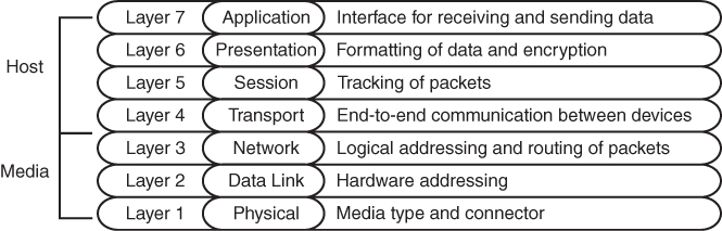
Figure 1-1 OSI Model
When you think about the flow of data, most network traffic involves communication of data between applications. The applications generate data at Layer 7, and the device/host sends data down the OSI model. As the data moves down the OSI model, it is encapsulated or modified as needed.
At Layer 3, the device/host decides whether the data needs to be sent to another application on the same device, and it would then start to move the data up the stack. Or, if the data needs to be sent to a different device, the device/host continues processing down the OSI model toward Layer 1. Layer 1 is responsible for transmitting the information on to the media (for example, cable, fiber, radio waves). On the receiving side, data starts at Layer 1, then moves to Layer 2, and so on, until it has moved completely up to Layer 7 and on to the receiving application.
This chapter reinforces concepts related to how a network device forwards traffic from either a Layer 2 or a Layer 3 perspective. The first Layer 2 network devices were bridges or switches, and Layer 3 devices were strictly routers. As technology advanced, the development of faster physical media required the ability to forward packets in hardware through ASICs. As ASIC functionality continued to develop, multilayer switches (MLSs) were invented to forward Layer 2 traffic in hardware as if they were switches; however, they can also perform other functions, such as routing packets, from a Layer 3 perspective.
Layer 2 Forwarding
The second layer of the OSI model, the data link layer, handles addressing beneath the IP protocol stack so that communication is directed between hosts. Network packets include Layer 2 addressing with unique source and destination addresses for segments. Ethernet commonly uses media access control (MAC) addresses, and other data link layer protocols such as Frame Relay use an entirely different method of Layer 2 addressing.
The focus of the Enterprise Core exam is on Ethernet and wireless technologies, both of which use MAC addresses for Layer 2 addressing. This book focuses on the MAC address for Layer 2 forwarding.
Collision Domains
The Ethernet protocol first used technologies like Thinnet (10BASE-2) and Thicknet (10BASE-5), which connected all the network devices using the same cable and T connectors. This caused problems when two devices tried to talk at the same time because the transmit cable shared the same segment with other devices, and the communication become garbled if two devices talked at the same time. Ethernet devices use Carrier Sense Multiple Access/Collision Detect (CSMA/CD) to ensure that only one device talks at time in a collision domain. If a device detects that another device is transmitting data, it delays transmitting packets until the cable is quiet. This means devices can only transmit or receive data at one time (that is, operate at half-duplex).
As more devices are added to a cable, the less efficient the network becomes as devices wait until there is not any communication. All of the devices are in the same collision domain. Network hubs proliferate the problem because they add port density while repeating traffic, thereby increasing the size of the collision domain. Network hubs do not have any intelligence in them to direct network traffic; they simply repeat traffic out of every port.
Network switches enhance scalability and stability in a network through the creation of virtual channels. A switch maintains a table that associates a host’s Media Access Control (MAC) Ethernet addresses to the port that sourced the network traffic. Instead of flooding all traffic out of every switch port, a switch uses the local MAC address table to forward network traffic only to the destination switch port associated with where the destination MAC is attached. This drastically reduces the size of the collision domain between the devices and enables the devices to transmit and receive data at the same time (that is, operate at full duplex).
Figure 1-2 demonstrates the collision domains on a hub versus on a switch. Both of these topologies show the same three PCs, as well as the same cabling. On the left, the PCs are connected to a network hub. Communication between PC-A and PC-B is received by PC-C’s NIC, too, because all three devices are in the same collision domain. PC-C must process the frame—in the process consuming resources—and then it discards the packet after determining that the destination MAC address does not belong to it. In addition, PC-C has to wait until the PC-A/PC-B conversation finishes before it can transmit data. On the right, the PCs are connected to a network switch. Communication between PC-A and PC-B are split into two collision domains. The switch can connect the two collision domains by using information from the MAC address table.
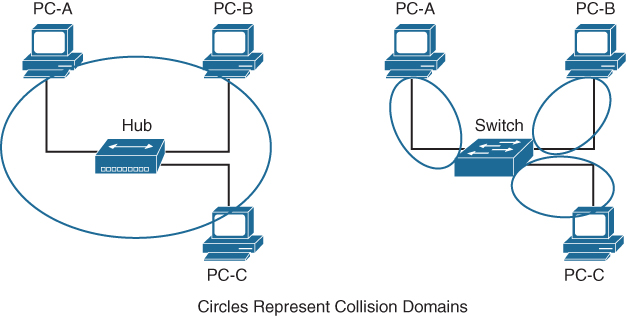
Figure 1-2 Collision Domains on a Hub Versus a Switch
When a packet contains a destination MAC address that is not in the switch’s MAC address table, the switch forwards the packet out of every switch port. This is known as unknown unicast flooding because the destination MAC address is not known.
Broadcast traffic is network traffic intended for every host on the LAN and is forwarded out of every switch port interface. This is disruptive as it diminishes the efficiencies of a network switch compared to those of a hub because it causes communication between network devices to stop due to CSMA/CD. Network broadcasts do not cross Layer 3 boundaries (that is, from one subnet to another subnet). All devices that reside in the same Layer 2 segment are considered to be in the same broadcast domain.
Figure 1-3 displays SW1’s MAC address table, which correlates the local PCs to the appropriate switch port. In the scenario on the left, PC-A is transmitting unicast traffic to PC-B. SW1 does not transmit data out of the Gi0/2 or Gi0/3 interface (which could potentially disrupt any network transmissions between those PCs). In the scenario on the right, PC-A is transmitting broadcast network traffic out all active switch ports.
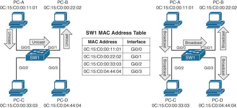
Figure 1-3 Unicast and Broadcast Traffic Patterns
Virtual LANs
Adding a router between LAN segments helps shrink broadcast domains and provides for optimal network communication. Host placement on a LAN segment varies because of network addressing. Poor host network assignment can lead to inefficient use of hardware as some switch ports could be unused.
Virtual LANs (VLANs) provide logical segmentation by creating multiple broadcast domains on the same network switch. VLANs provide higher utilization of switch ports because a port can be associated to the necessary broadcast domain, and multiple broadcast domains can reside on the same switch. Network devices in one VLAN cannot communicate with devices in a different VLAN via traditional Layer 2 or broadcast traffic.
VLANs are defined in the Institute of Electrical and Electronic Engineers (IEEE) 802.1Q standard, which states that 32 bits are added to the packet header in the following fields:
Tag protocol identifier (TPID): This 16-bit is field set to 0x8100 to identify the packet as an 802.1Q packet.
Priority code point (PCP): This 3-bit field indicates a class of service (CoS) as part of Layer 2 quality of service (QoS) between switches.
Drop elgible indicator (DEI): This 1-bit field indicates whether the packet can be dropped when there is bandwidth contention.
VLAN identifier (VLAN ID): This 12-bit field specifies the VLAN associated with a network packet.
Figure 1-4 displays the VLAN packet structure.
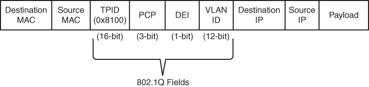
Figure 1-4 VLAN Packet Structure
The VLAN identifier has only 12 bits, which provides 4094 unique VLANs. Catalyst switches use the following logic for VLAN identifiers:
VLAN 0 is reserved for 802.1P traffic and cannot be modified or deleted.
VLAN 1 is the default VLAN and cannot be modified or deleted.
VLANs 2 to 1001 are in the normal VLAN range and can be added, deleted, or modified as necessary.
VLANS 1002 to 1005 are reserved and cannot be deleted.
VLANs 1006 to 4094 are in the extended VLAN range and can be added, deleted, or modified as necessary.
VLANs are created by using the global configuration command vlan vlan-id. A friendly name (32 characters) is associated with a VLAN through the VLAN submode configuration command name vlanname. The VLAN is not created until the command-line interface (CLI) has been moved back to the global configuration context or a different VLAN identifier.
Example 1-1 demonstrates the creation of VLAN 10 (PCs), VLAN 20 (Phones), and VLAN 99 (Guest) on SW1.
Example 1-1 Creating a VLAN
SW1# configure term
Enter configuration commands, one per line. End with CNTL/Z.
SW1(config)# vlan 10
SW1(config-vlan)# name PCs
SW1(config-vlan)# vlan 20
SW1(config-vlan)# name Phones
SW1(config-vlan)# vlan 99
SW1(config-vlan)# name Gues
VLANs and their port assignment are verified with the show vlan [{brief | id vlan-id | name vlanname | summary}] command, as demonstrated in Example 1-2. Notice that the output is split into four main sections: VLAN-to-port assignments, system MTU, SPAN sessions, and private VLANs.
Example 1-2 Viewing VLAN Assignments to Port Mapping
SW1# show vlan
! Traditional and common VLANs will be listed in this section. The ports
! associated to these VLANs are displayed to the right.
VLAN Name                             Status    Ports
---- -------------------------------- --------- -------------------------------
1    default                          active    Gi1/0/1, Gi1/0/2, Gi1/0/3
                                                Gi1/0/4, Gi1/0/5, Gi1/0/6
                                                Gi1/0/10, Gi1/0/11, Gi1/0/17
                                                Gi1/0/18, Gi1/0/19, Gi1/0/20
                                                Gi1/0/21, Gi1/0/22, Gi1/0/23
                                                Gi1/1/1, Gi1/1/2, Te1/1/3
                                                Te1/1/4
10   PCs                              active    Gi1/0/7, Gi1/0/8, Gi1/0/9
                                                Gi1/0/12, Gi1/0/13
20   Phones                           active    Gi1/0/14
99   Guest                            active    Gi1/0/15, Gi1/0/1
1002 fddi-default                     act/unsup
1003 token-ring-default               act/unsup
1004 fddinet-default                  act/unsup
1005 trnet-default                    act/unsup
!  This section displays the system wide MTU setting for all 1Gbps and faster
!  interface

VLAN Type  SAID       MTU   Parent RingNo BridgeNo Stp  BrdgMode Trans1 Trans2
---- ----- ---------- ----- ------ ------ -------- ---- -------- ------ ------

VLAN Type  SAID       MTU   Parent RingNo BridgeNo Stp  BrdgMode Trans1 Trans2
---- ----- ---------- ----- ------ ------ -------- ---- -------- ------ ------
1    enet  100001     1500  -      -      -        -    -        0      0
10   enet  100010     1500  -      -      -        -    -        0      0
20   enet  100020     1500  -      -      -        -    -        0      0
99   enet  100099     1500  -      -      -        -    -        0      0
1002 fddi  101002     1500  -      -      -        -    -        0      0
1003 tr    101003     1500  -      -      -        -    -        0      0
1004 fdnet 101004     1500  -      -      -        ieee -        0      0
1005 trnet 101005     1500  -      -      -        ibm  -        0      0

!  If a Remote SPAN VLAN is configured, it will be displayed in this section.
!  Remote SPAN VLANs are explained in Chapter 24
Remote SPAN VLANs
------------------------------------------------------------------------------

!  If Private VLANs are configured, they will be displayed in this section.
!  Private VLANs are outside of the scope of this book, but more information
!  can be found at http://www.cisco.com
Primary Secondary Type              Ports
------- --------- ----------------- -----------------------------------------
The optional show vlan keywords provide the following benefits:
brief: Displays only the relevant port-to-VLAN mappings.
summary: Displays a count of VLANS, VLANs participating in VTP, and VLANs that are in the extended VLAN range.
id vlan-id: Displays all the output from the original command but filtered to only the VLAN number that is specified.
name vlanname: Displays all the output from the original command but filtered to only the VLAN name that is specified.
Example 1-3 shows the use of the optional keywords. Notice that the output from the optional keywords id vlan-id is the same as the output from name vlanname.
Example 1-3 Using the Optional show vlan Keywords
SW1# show vlan brief

VLAN Name                             Status    Ports
---- -------------------------------- --------- -------------------------------
1    default                          active    Gi1/0/1, Gi1/0/2, Gi1/0/3
                                                Gi1/0/4, Gi1/0/5, Gi1/0/6
                                                Gi1/0/10, Gi1/0/11, Gi1/0/17
                                                Gi1/0/18, Gi1/0/19, Gi1/0/20
                                                Gi1/0/21, Gi1/0/22, Gi1/0/23
                                                Gi1/1/1, Gi1/1/2, Te1/1/3
                                                Te1/1/4
10   PCs                              active    Gi1/0/7, Gi1/0/8, Gi1/0/9
                                                Gi1/0/12, Gi1/0/13
20   Phones                           active    Gi1/0/14
99   Guest                            active    Gi1/0/15, Gi1/0/16
1002 fddi-default                     act/unsup
1003 token-ring-default               act/unsup
1004 fddinet-default                  act/unsup
1005 trnet-default                    act/unsup
SW1# show vlan summary
Number of existing VLANs               : 8
 Number of existing VTP VLANs          : 8
 Number of existing extended VLANS     : 0
SW1# show vlan id 99

VLAN Name                             Status    Ports
---- -------------------------------- --------- -------------------------------
99   Guest                            active    Gi1/0/15, Gi1/0/16

VLAN Type  SAID       MTU   Parent RingNo BridgeNo Stp  BrdgMode Trans1 Trans2
---- ----- ---------- ----- ------ ------ -------- ---- -------- ------ ------
99   enet  100099     1500  -      -      -        -    -        0      0

Remote SPAN VLAN
----------------
Disabled

Primary Secondary Type              Ports
------- --------- ----------------- -----------------------------------------

SW1# show vlan name Guest

VLAN Name                             Status    Ports
---- -------------------------------- --------- -------------------------------
99   Guest                            active    Gi1/0/15, Gi1/0/16

VLAN Type  SAID       MTU   Parent RingNo BridgeNo Stp  BrdgMode Trans1 Trans2
---- ----- ---------- ----- ------ ------ -------- ---- -------- ------ ------
99   enet  100099     1500  -      -      -        -    -        0      0

Remote SPAN VLAN
----------------
Disabled

Primary Secondary Type              Ports
------- --------- ----------------- -----------------------------------------
Access Ports
Access ports are the fundamental building blocks of a managed switch. An access port is assigned to only one VLAN. It carries traffic from the specified VLAN to the device connected to it or from the device to other devices on the same VLAN on that switch. The 802.1Q tags are not included on packets transmitted or received on access ports.
Catalyst switches place switch ports as Layer 2 access ports for VLAN 1 by default. The port can be manually configured as an access port with the command switchport mode access. A specific VLAN is associated to the port with the command switchport access {vlan vlan-id | name vlanname}. The ability to set VLANs to an access port by name was recently added with newer code but is stored in numeric form in the configuration.
Example 1-4 demonstrates the configuration of switch ports Gi1/0/15 and Gi1/0/16 as access ports in VLAN 99 for Guests. Notice that the final configuration is stored as numbers for both ports, even though different commands are issued.
Example 1-4 Configuring an Access Port
SW1# configure terminal
Enter configuration commands, one per line. End with CNTL/Z.
SW1(config)# vlan 99
SW1(config-vlan)# name Guests
SW1(config-vlan)# interface gi1/0/15
SW1(config-if)# switchport mode access
SW1(config-if)# switchport access vlan 99
SW1(config-if)# interface gi1/0/16
SW1(config-if)# switchport mode access
SW1(config-if)# switchport access vlan name Gues

SW1# show running-config | begin interface GigabitEthernet1/0/15
interface GigabitEthernet1/0/15
 switchport access vlan 99
 switchport mode access
!
interface GigabitEthernet1/0/16
 switchport access vlan 99
 switchport mode acces
Trunk Ports
Trunk ports can carry multiple VLANs. Trunk ports are typically used when multiple VLANs need connectivity between a switch and another switch, router, or firewall and use only one port. Upon receipt of the packet on the remote trunk link, the headers are examined, traffic is associated to the proper VLAN, then the 802.1Q headers are removed, and traffic is forwarded to the next port, based on MAC address for that VLAN.
Trunk ports are statically defined on Catalyst switches with the interface command switchport mode trunk. Example 1-5 displays Gi1/0/2 and Gi1/0/3 being converted to a trunk port.
Example 1-5 Configuring a Trunk Port
SW1# configure terminal
Enter configuration commands, one per line. End with CNTL/Z.
SW1(config)# interface gi1/0/2
SW1(config-if)# switchport mode trunk
SW1(config-if)# interface gi1/0/3
SW1(config-if)# switchport mode trun
The command show interfaces trunk provides a lot of valuable information in several sections for troubleshooting connectivity between network devices:
The first section lists all the interfaces that are trunk ports, the status, the association to an EtherChannel, and whether a VLAN is a native VLAN. Native VLANs are explained in the next section. EtherChannel is explained in Chapter 5, “VLAN Trunks and EtherChannel Bundles.”
The second section of the output displays the list of VLANs that are allowed on the trunk port. Traffic can be minimized on trunk ports to restrict VLANs to specific switches, thereby restricting broadcast traffic, too. Other use cases involve a form of load balancing between network links where select VLANs are allowed on one trunk link, while a different set of VLANs are allowed on a different trunk port.
The third section displays the VLANs that are in a forwarding state on the switch. Ports that are in blocking state are not listed in this section.
Example 1-6 demonstrates the use of the show interfaces trunk command with an explanation of each section.
Example 1-6 Verifying Trunk Port Status
SW1# show interfaces trunk
! Section 1 displays the native VLAN associated on this port, the status and
! if the port is associated to a EtherChannel

Port        Mode             Encapsulation  Status        Native vlan
Gi1/0/2     on               802.1q         trunking      1
Gi1/0/3     on               802.1q         trunking      1

! Section 2 displays all of the VLANs that are allowed to be transmitted across
! the trunk ports

Port        Vlans allowed on trunk
Gi1/0/2     1-4094
Gi1/0/3     1-4094

Port        Vlans allowed and active in management domain
Gi1/0/2     1,10,20,99
Gi1/0/3     1,10,20,99

! Section 3 displays all of the VLANs that are allowed across the trunk and are
! in a spanning tree forwarding state

Port        Vlans in spanning tree forwarding state and not pruned
Gi1/0/2     1,10,20,99
Gi1/0/3     1,10,20,99
Native VLANs
In the 802.1Q standard, any traffic that is advertised or received on a trunk port without the 802.1Q VLAN tag is associated to the native VLAN. The default native VLAN is VLAN 1. This means that when a switch has two access ports configured as access ports and associated to VLAN 10—that is, a host attached to a trunk port with a native VLAN set to 10—the host could talk to the devices connected to the access ports.
The native VLAN should match on both trunk ports, or traffic can change VLANs unintentionally. While connectivity between hosts is feasible (assuming that they are on the different VLAN numbers), this causes confusion for most network engineers and is not a best practice.
A native VLAN is a port-specific configuration and is changed with the interface command switchport trunk native vlan vlan-id.
Allowed VLANs
As stated earlier, VLANs can be restricted from certain trunk ports as a method of traffic engineering. This can cause problems if traffic between two hosts is expected to traverse a trunk link and the VLAN is not allowed to traverse that trunk port. The interface command switchport trunk allowed vlan vlan-ids specifies the VLANs that are allowed to traverse the link. Example 1-7 displays sample a configuration for limiting the VLANs that can cross the Gi1/0/2 trunk port for VLANs 1, 10, 20, and 99.
Example 1-7 Viewing the VLANs That Are Allowed on a Trunk Link
SW1# show run interface gi1/0/1
interface GigabitEthernet1/0/1
 switchport trunk allowed vlan 1,10,20,99
 switchport mode trun
The full command syntax switchport trunk allowed {vlan-ids | all | none | add vlan-ids | remove vlan-ids | except vlan-ids} provides a lot of power in a single command. The optional keyword all allows for all VLANs, while none removes all VLANs from the trunk link. The add keyword adds additional VLANs to those already listed, and the remove keyword removes the specified VLAN from the VLANs already identified for that trunk link.
Layer 2 Diagnostic Commands
The information in the “Layer 2 Forwarding” section, earlier in this chapter, provides a brief primer on the operations of a switch. The following sections provide some common diagnostic commands that are used in the daily administration, operation, and troubleshooting of a network.
MAC Address Table
The MAC address table is responsible for identifying the switch ports and VLANs with which a device is associated. A switch builds the MAC address table by examining the source MAC address for traffic that it receives. This information is then maintained to shrink the collision domain (point-to-point communication between devices and switches) by reducing the amount of unknown unicast flooding.
The MAC address table is displayed with the command show mac address-table [address mac-address | dynamic | vlan vlan-id]. The optional keywords with this command provide the following benefits:
address mac-address: Displays entries that match the explicit MAC address. This command could be beneficial on switches with hundreds of ports.
dynamic: Displays entries that are dynamically learned and are not statically set or burned in on the switch.
vlan vlan-id: Displays entries that matches the specified VLAN.
Example 1-8 shows the MAC address table on a Catalyst. The command in this example displays the VLAN, MAC address, type, and port that the MAC address is connected to. Notice that port Gi1/0/3 has multiple entries, which indicates that this port is connected to a switch.
Example 1-8 Viewing the MAC Address Table
SW1# show mac address-table dynamic
          Mac Address Table
-------------------------------------------

Vlan    Mac Address       Type        Ports
----    -----------       --------    -----
   1    0081.c4ff.8b01    DYNAMIC     Gi1/0/2
   1    189c.5d11.9981    DYNAMIC     Gi1/0/3
   1    189c.5d11.99c7    DYNAMIC     Gi1/0/3
   1    7070.8bcf.f828    DYNAMIC     Gi1/0/17
   1    70df.2f22.b882    DYNAMIC     Gi1/0/2
   1    70df.2f22.b883    DYNAMIC     Gi1/0/3
   1    bc67.1c5c.9304    DYNAMIC     Gi1/0/2
   1    bc67.1c5c.9347    DYNAMIC     Gi1/0/3
  99    189c.5d11.9981    DYNAMIC     Gi1/0/3
  99    7069.5ad4.c228    DYNAMIC     Gi1/0/15
  10    0087.31ba.3980    DYNAMIC     Gi1/0/9
  10    0087.31ba.3981    DYNAMIC     Gi1/0/9
  10    189c.5d11.9981    DYNAMIC     Gi1/0/3
  10    3462.8800.6921    DYNAMIC     Gi1/0/8
  10    5067.ae2f.6480    DYNAMIC     Gi1/0/7
  10    7069.5ad4.c220    DYNAMIC     Gi1/0/13
  10    e8ed.f3aa.7b98    DYNAMIC     Gi1/0/12
  20    189c.5d11.9981    DYNAMIC     Gi1/0/3
  20    7069.5ad4.c221    DYNAMIC     Gi1/0/14
Total Mac Addresses for this criterion: 19
Some older technologies (such as load balancing) require a static MAC address entry in the MAC address table to prevent unknown unicast flooding. The command mac address-table static mac-address vlan vlan-id {drop | interface interface-id} adds a manual entry with the ability to associate it to a specific switch port or to drop traffic upon receipt.
The command clear mac address-table dynamic [{address mac-address | interface interface-id | vlan vlan-id}] flushes the MAC address table for the entire switch. Using the optional keywords can flush the MAC address table for a specific MAC address, switch port, or interface.
The MAC address table resides in content addressable memory (CAM). The CAM uses high-speed memory that is faster than typical computer RAM due to its search techniques. The CAM table provides a binary result for any query of 0 for true or 1 for false. The CAM is used with other functions to analyze and forward packets very quickly. Switches are built with large CAM to accommodate all the Layer 2 hosts for which they must maintain forwarding tables.
Switch Port Status
Examining the configuration for a switch port can be useful; however, some commands stored elsewhere in the configuration preempt the configuration set on the interface. The command show interfaces interface-id switchport provides all the relevant information for a switch port’s status. The command show interfaces switchport displays the same information for all ports on the switch.
Example 1-9 shows the output from the show interfaces gi1/0/5 switchport command on SW1. The key fields to examine at this time are the switch port state, operational mode, and access mode VLAN.
Example 1-9 Viewing the Switch Port Status
SW1# show interfaces gi1/0/5 switchport
Name: Gi1/0/5
! The following line indicates if the port is shut or no shut
Switchport: Enabled
Administrative Mode: dynamic auto
! The following line indicates if the port is acting as static access port, trunk
! port, or if is down due to carrier detection (i.e. link down)
Operational Mode: down
Administrative Trunking Encapsulation: dot1q
Negotiation of Trunking: On
! The following line displays the VLAN assigned to the access port
Access Mode VLAN: 1 (default)
Trunking Native Mode VLAN: 1 (default)
Administrative Native VLAN tagging: enabled
Voice VLAN: none
Administrative private-vlan host-association: none
Administrative private-vlan mapping: none
Administrative private-vlan trunk native VLAN: none
Administrative private-vlan trunk Native VLAN tagging: enabled
Administrative private-vlan trunk encapsulation: dot1q
Administrative private-vlan trunk normal VLANs: none
Administrative private-vlan trunk associations: none
Administrative private-vlan trunk mappings: none
Operational private-vlan: none
Trunking VLANs Enabled: ALL
Pruning VLANs Enabled: 2-1001
Capture Mode Disabled
Capture VLANs Allowed: ALL

Protected: false
Unknown unicast blocked: disabled
Unknown multicast blocked: disabled
Appliance trust: non
Interface Status
The command show interface status is another useful command for viewing the status of switch ports in a very condensed and simplified manner. Example 1-10 demonstrates the use of this command and includes following fields in the output:
Port: Displays the interface ID or port channel.
Name: Displays the configured interface description.
Status: Displays connected for links where a connection was detected and established to bring up the link. Displays notconnect for when a link is not detected and err-disabled when an error has been detected and the switch has disabled the ability to forward traffic out of that port.
VLAN: Displays the VLAN number assigned for access ports. Trunk links appear as trunk, and ports configured as Layer 3 interfaces display routed.
Duplex: Displays the duplex of the port. If the duplex auto-negotiated, it is prefixed by a-.
Speed: Displays the speed of the port. If the port speed was auto-negotiated, it is prefixed by a-.
Type: Displays the type of interface for the switch port. If it is a fixed RJ-45 copper port, it includes TX in the description (for example, 10/100/1000BASE-TX). Small form-factor pluggable (SFP)–based ports are listed with the SFP model if there is a driver for it in the software; otherwise, it says unknown.
Example 1-10 Viewing Overall Interface Status
SW1# show interface status

Port      Name              Status       Vlan       Duplex  Speed Type
Gi1/0/1                     notconnect   1            auto   auto 10/100/1000BaseTX
Gi1/0/2   SW-2 Gi1/0/1      connected    trunk      a-full a-1000 10/100/1000BaseTX
Gi1/0/3   SW-3 Gi1/0/1      connected    trunk      a-full a-1000 10/100/1000BaseTX
Gi1/0/4                     notconnect   1            auto   auto 10/100/1000BaseTX
Gi1/0/5                     notconnect   1            auto   auto 10/100/1000BaseTX
Gi1/0/6                     notconnect   1            auto   auto 10/100/1000BaseTX
Gi1/0/7   Cube13.C          connected    10         a-full a-1000 10/100/1000BaseTX
Gi1/0/8   Cube11.F          connected    10         a-full a-1000 10/100/1000BaseTX
Gi1/0/9   Cube10.A          connected    10         a-full  a-100 10/100/1000BaseTX
Gi1/0/10                    notconnect   1            auto   auto 10/100/1000BaseTX
Gi1/0/11                    notconnect   1            auto   auto 10/100/1000BaseTX
Gi1/0/12  Cube14.D Phone    connected    10         a-full a-1000 10/100/1000BaseTX
Gi1/0/13  R1-G0/0/0         connected    10         a-full a-1000 10/100/1000BaseTX
Gi1/0/14  R2-G0/0/1         connected    20         a-full a-1000 10/100/1000BaseTX
Gi1/0/15  R3-G0/1/0         connected    99         a-full a-1000 10/100/1000BaseTX
Gi1/0/16  R4-G0/1/1         connected    99         a-full a-1000 10/100/1000BaseTX
Gi1/0/17                    connected    1          a-full a-1000 10/100/1000BaseTX
Gi1/0/18                    notconnect   1            auto   auto 10/100/1000BaseTX
Gi1/0/19                    notconnect   1            auto   auto 10/100/1000BaseTX
Gi1/0/20                    notconnect   1            auto   auto 10/100/1000BaseTX
Gi1/0/21                    notconnect   1            auto   auto 10/100/1000BaseTX
Gi1/0/22                    notconnect   1            auto   auto 10/100/1000BaseTX
Gi1/0/23                    notconnect   routed       auto   auto 10/100/1000BaseTX
Gi1/0/24                    disabled     4011         auto   auto 10/100/1000BaseTX
Te1/1/1                     notconnect   1            full    10G SFP-10GBase-SR
Te1/1/2                     notconnect   1            auto   auto unknow
Layer 3 Forwarding
Now that we have looked at the mechanisms of a switch and how it forwards Layer 2 traffic, let’s review the process for forwarding a packet from a Layer 3 perspective. Recall that all traffic starts at Layer 7 and works its way down to Layer 1, so some of the Layer 3 forwarding logic occurs before Layer 2 forwarding. There are two main methodologies for Layer 3 forwarding:
Forwarding traffic to devices on the same subnet
Forwarding traffic to devices on a different subnet
The following sections explain these two methodologies.
Local Network Forwarding
Two devices that reside on the same subnet communicate locally. As the data is encapsulated with its IP address, the device detects that the destination is on the same network. However, the device still needs to encapsulate the Layer 2 information (that is, the source and destination MAC addresses) to the packet. It knows its own MAC address but does not initially know the destination’s MAC address.
The Address Resolution Protocol (ARP) table provides a method of mapping Layer 3 IP addresses to Layer 2 MAC addresses by storing the IP address of a host and its corresponding MAC address. The device then uses the ARP table to add the appropriate Layer 2 headers to the data packet before sending it down to Layer 2 for processing and forwarding.
For example, an IP host that needs to perform address resolution for another IP host connected by Ethernet can send an ARP request using the LAN broadcast address, and it then waits for an ARP reply from the IP host. The ARP reply includes the required Layer 2 physical MAC address information.
The ARP table contains entries for remote devices that the host has communicated with recently and that are on the same IP network segment. It does not contain entries for devices on a remote network but does contain the ARP entry for the IP address of the next hop to reach the remote network. If communication has not occurred with a host after a length of time, the entry becomes stale and is removed from the local ARP table.
If an entry does not exist in the local ARP table, the device broadcasts an ARP request to the entire Layer 2 switching segment. The ARP request strictly asks that whoever owns the IP address in the ARP request reply. All hosts in the Layer 2 segment receive the response, but only the device with the matching IP address should respond to the request.
The response is unicast and includes the MAC and IP addresses of the requestor. The device then updates its local ARP table upon receipt of the ARP reply, adds the appropriate Layer 2 headers, and sends the original data packet down to Layer 2 for processing and forwarding.
Packet Routing
Packets must be routed when two devices are on different networks. As the data is encapsulated with its IP address, a device detects that its destination is on a different network and must be routed. The device checks its local routing table to identify its next-hop IP address, which may be learned in one of several ways:
From a static route entry, it can get the destination network, subnet mask, and next-hop IP address.
A default-gateway is a simplified static default route that just asks for the local next-hop IP address for all network traffic.
Routes can be learned from routing protocols.
The source device must add the appropriate Layer 2 headers (source and destination MAC addresses), but the destination MAC address is needed for the next-hop IP address. The device looks for the next-hop IP addresses entry in the ARP table and uses the MAC address from the next-hop IP address’s entry as the destination MAC address. The next step is to send the data packet down to Layer 2 for processing and forwarding.
The next router receives the packet based on the destination MAC address, analyzes the destination IP address, locates the appropriate network entry in its routing table, identifies the outbound interface, and then finds the MAC address for the destination device (or the MAC address for the next-hop address if it needs to be routed further). The router then modifies the source MAC address to the MAC address of the router’s outbound interface and modifies the destination MAC address to the MAC address for the destination device (or next-hop router).
Figure 1-5 illustrates the concept, with PC-A sending a packet to PC-B through an Ethernet connection to R1. PC-A sends the packet to R1’s MAC address, 00:C1:5C:00:00:A1. R1 receives the packet, removes the Layer 2 information, and looks for a route to the 192.168.2.2 address. R1 identifies that connectivity to the 192.168.2.2 IP address is through Gigabit Ethernet 0/1. R1 adds the Layer 2 source address by using its Gigabit Ethernet 0/1 MAC address 00:C1:5C:00:00:B1 and the destination address 00:00:00:BB:BB:BB for PC-B.
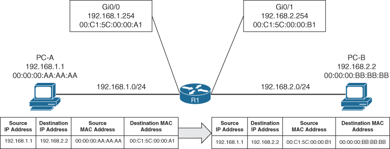
Figure 1-5 Layer 2 Addressing Rewrite
IP Address Assignment
TCP/IP has become the standard protocol for most networks. Initially it was used with IPv4 and 32-bit network addresses. The number of devices using public IP addresses has increased at an exponential rate and depleted the number of publicly available IP addresses. To deal with the increase in the number of addresses, a second standard, called IPv6, was developed in 1998; it provides 128 bits for addressing. Technologies and mechanisms have been created to allow IPv4 and IPv6 networks to communicate with each other. With either version, an IP address must be assigned to an interface for a router or multilayer switch to route packets.
IPv4 addresses are assigned with the interface configuration command ip address ip-address subnet-mask. An interface with a configured IP address and that is in an up state injects the associated network into the router’s routing table (Routing Information Base [RIB]). Connected networks or routes have an administrative distance (AD) of zero. It is not possible for any other routing protocol to preempt a connected route in the RIB.
It is possible to attach multiple IPv4 networks to the same interface by attaching a secondary IPv4 address to the same interface with the command ip address ip-address subnet-mask secondary.
IPv6 addresses are assigned with the interface configuration command ipv6 address ipv6-address/prefix-length. This command can be repeated multiple times to add multiple IPv6 addresses to the same interface.
Example 1-11 demonstrates the configuration of IP addresses on routed interfaces. A routed interface is basically any interface on a router. Notice that a second IPv4 address requires the use of the secondary keyword; the ipv6 address command can be used multiple times to configure multiple IPv6 addresses.
Example 1-11 Assigning IP Addresses to Routed Interfaces
R1# configure terminal
Enter configuration commands, one per line. End with CNTL/Z.
R1(config)# interface gi0/0/0
R1(config-if)# ip address 10.10.10.254 255.255
R1(config-if)# ip address 172.16.10.254 255.255.255.0 secondary
R1(config-if)# ipv6 address 2001:db8:10::254/64
R1(config-if)# ipv6 address 2001:DB8:10:172::254/64
R1(config-if)# interface gi0/0/1
R1(config-if)# ip address 10.20.20.254 255.255.255.0
R1(config-if)# ip address 172.16.20.254 255.255.255.0 secondary
R1(config-if)# ipv6 address 2001:db8:20::254/64
R1(config-if)# ipv6 address 2001:db8:20:172::254/6
Routed Subinterfaces
In the past, there might have been times when multiple VLANs on a switch required routing, and there were not enough physical router ports to accommodate all those VLANs. It is possible to overcome this issue by configuring the switch’s interface as a trunk port and creating logical subinterfaces on a router. A subinterface is created by appending a period and a numeric value after the period. Then the VLAN needs to be associated with the subinterface with the command encapsulation dot1q vlan-id.
Example 1-12 demonstrates the configuration of two subinterfaces on R2. The subinterface number does not have to match the VLAN ID, but if it does, it helps with operational support.
Example 1-12 Configuring Routed Subinterfaces
R2# configure terminal
Enter configuration commands, one per line. End with CNTL/Z.
R2(config-if)# int g0/0/1.10
R2(config-subif)# encapsulation dot1Q 10
R2(config-subif)# ip address 10.10.10.2 255.255.255.0
R2(config-subif)# ipv6 address 2001:db8:10::2/64
R2(config-subif)# int g0/0/1.99
R2(config-subif)# encapsulation dot1Q 99
R2(config-subif)# ip address 10.20.20.2 255.255.255.0
R2(config-subif)# ipv6 address 2001:db8:20::2/6
Switched Virtual Interfaces
With Catalyst switches it is possible to assign an IP address to a switched virtual interface (SVI), also known as a VLAN interface. An SVI is configured by defining the VLAN on the switch and then defining the VLAN interface with the command interface vlan vlan-id. The switch must have an interface associated to that VLAN in an up state for the SVI to be in an up state. If the switch is a multilayer switch, the SVIs can be used for routing packets between VLANs without the need of an external router.
Example 1-13 demonstrates the configuration of the SVI for VLANs 10 and 99.
Example 1-13 Creating a Switched Virtual Interface (SVI)
SW1# configure terminal
Enter configuration commands, one per line. End with CNTL/Z.
SW1(config)# interface Vlan 10
SW1(config-if)# ip address 10.10.10.1 255.255.255.0
SW1(config-if)# ipv6 address 2001:db8:10::1/64
SW1(config-if)# no shutdown
SW1(config-if)# interface vlan 99
SW1(config-if)# ip address 10.99.99.1 255.255.255.0
SW1(config-if)# ipv6 address 2001:db8:99::1/64
SW1(config-if)# no shutdow
Routed Switch Ports
Some network designs include a point-to-point link between switches for routing. For example, when a switch needs to connect to a router, some network engineers would build out a transit VLAN (for example, VLAN 2001), associate the port connecting to the router to VLAN 2001, and then build an SVI for VLAN 2001. There is always the potential that VLAN 2001 could exist elsewhere in the Layer 2 realm or that spanning tree could impact the topology.
Instead, the multilayer switch port can be converted from a Layer 2 switch port to a routed switch port with the interface configuration command no switchport. Then the IP address can be assigned to it. Example 1-14 demonstrates port Gi1/0/14 being converted from a Layer 2 switch port to a routed switch port and then having an IP address assigned to it.
Example 1-14 Configuring a Routed Switch Port
SW1# configure terminal
Enter configuration commands, one per line. End with CNTL/Z.
SW1(config)# int gi1/0/14
SW1(config-if)# no switchport
SW1(config-if)# ip address 10.20.20.1 255.255.255.0
SW1(config-if)# ipv6 address 2001:db8:20::1/64
SW1(config-if)# no shutdow
Verification of IP Addresses
IPv4 addresses can be viewed with the command show ip interface [brief | interface-id | vlan vlan-id]. This command’s output contains a lot of useful information, such as MTU, DHCP relay, ACLs, and the primary IP address. The optional brief keyword displays the output in a condensed format. However, on devices with large port counts, using the CLI parser and adding an additional | exclude field (for example, unassigned) yields a streamlined view of interfaces that are configured with IP addresses.
Example 1-15 shows the show ip interface brief command used with and without the CLI parser. Notice the drastic reduction in unnecessary data that is presented.
Example 1-15 Viewing Device IPv4 Addresses
SW1# show ip interface brief
Interface              IP-Address      OK? Method Status                Protocol
Vlan1                  unassigned      YES manual up                    up
Vlan10                 10.10.10.1      YES manual up                    up
Vlan99                 10.99.99.1      YES manual up                    up
GigabitEthernet0/0     unassigned      YES unset  down                  down
GigabitEthernet1/0/1   unassigned      YES unset  down                  down
GigabitEthernet1/0/2   unassigned      YES unset  up                    up
GigabitEthernet1/0/3   unassigned      YES unset  up                    up
GigabitEthernet1/0/4   unassigned      YES unset  down                  down
GigabitEthernet1/0/5   unassigned      YES unset  down                  down
GigabitEthernet1/0/6   unassigned      YES unset  down                  down
GigabitEthernet1/0/7   unassigned      YES unset  up                    up
GigabitEthernet1/0/8   unassigned      YES unset  up                    up
GigabitEthernet1/0/9   unassigned      YES unset  up                    up
GigabitEthernet1/0/10  unassigned      YES unset  down                  down
GigabitEthernet1/0/11  unassigned      YES unset  down                  down
GigabitEthernet1/0/12  unassigned      YES unset  down                  down
GigabitEthernet1/0/13  unassigned      YES unset  up                    up
GigabitEthernet1/0/14  10.20.20.1      YES manual up                    up
GigabitEthernet1/0/15  unassigned      YES unset  up                    up
GigabitEthernet1/0/16  unassigned      YES unset  up                    up
GigabitEthernet1/0/17  unassigned      YES unset  down                  dow
SW1# show ip interface brief | exclude unassigned
Interface              IP-Address      OK? Method Status                Protocol
Vlan10                 10.10.10.1      YES manual up                    up
Vlan99                 10.99.99.1      YES manual up                    up
GigabitEthernet1/0/14  10.20.20.1      YES manual up                    up
GigabitEthernet1/0/23  192.168.1.1     YES manual down                  dow
The same information can be viewed for IPv6 addresses with the command show ipv6 interface [brief | interface-id | vlan vlan-id]. Just as with IPv4 addresses, a CLI parser can be used to reduce the information to what is relevant, as demonstrated in Example 1-16.
Example 1-16 Viewing Device IPv6 Addresses
SW1# show ipv6 interface brief
! Output omitted for brevity
Vlan1                  [up/up]
    FE80::262:ECFF:FE9D:C547
    2001:1::1
Vlan10                 [up/up]
    FE80::262:ECFF:FE9D:C546
    2001:DB8:10::1
Vlan99                 [up/up]
    FE80::262:ECFF:FE9D:C55D
    2001:DB8:99::1
GigabitEthernet0/0     [down/down]
    unassigned
GigabitEthernet1/0/1   [down/down]
    unassigned
GigabitEthernet1/0/2   [up/up]
    unassigned
GigabitEthernet1/0/3   [up/up]
    unassigned
GigabitEthernet1/0/4   [down/down]
    unassigned
GigabitEthernet1/0/5   [down/down]
    Unassigned
SW1# show ipv6 interface brief | exclude unassigned|GigabitEthernet
Vlan1                  [up/up]
    FE80::262:ECFF:FE9D:C547
    2001:1::1
Vlan10                 [up/up]
    FE80::262:ECFF:FE9D:C546
    2001:DB8:10::1
Vlan99                 [up/up]
    FE80::262:ECFF:FE9D:C55D
    2001:DB8:99::
Forwarding Architectures
The first Cisco routers would receive a packet, remove the Layer 2 information, and verify that the route existed for the destination IP address. If a matching route could not be found, the packet was dropped. If a matching route was found, the router would identify and add new Layer 2 header information to the packet.
Advancements in technologies have streamlined the process so that routers do not remove and add the Layer 2 addressing but simply rewrite the addresses. IP packet switching or IP packet forwarding is a faster process for receiving an IP packet on an input interface and making a decision about whether to forward the packet to an output interface or drop it. This process is simple and streamlined so that a router can forward large numbers of packets.
When the first Cisco routers were developed, they used a mechanism called process switching to switch the packets through the routers. As network devices evolved, Cisco created fast switching and Cisco Express Forwarding (CEF) to optimize the switching process for the routers to be able to handle larger packet volumes.
Process Switching
Process switching, also referred to as software switching or slow path, is a switching mechanism in which the general-purpose CPU on a router is in charge of packet switching. In IOS, the ip_input process runs on the general-purpose CPU for processing incoming IP packets. Process switching is the fallback for CEF because it is dedicated to processing punted IP packets when they cannot be switched by CEF.
The types of packets that require software handling include the following:
Packets sourced or destined to the router (using control traffic or routing protocols)
Packets that are too complex for the hardware to handle (that is, IP packets with IP options)
Packets that require extra information that is not currently known (for example, ARP)
Figure 1-6 illustrates how a packet that cannot be CEF switched is punted to the CPU for processing. The ip_input process consults the routing table and ARP table to obtain the next-hop router’s IP address, outgoing interface, and MAC address. It then overwrites the destination MAC address of the packet with the next-hop router’s MAC address, overwrites the source MAC address with the MAC address of the outgoing Layer 3 interface, decrements the IP time-to-live (TTL) field, recomputes the IP header checksum, and finally delivers the packet to the next-hop router.
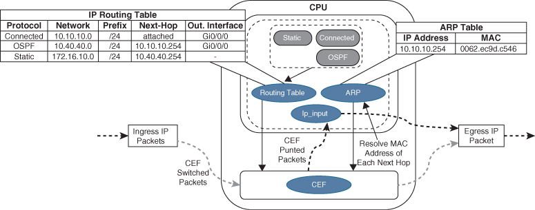
Figure 1-6 Process Switching
The routing table, also known as the Routing Information Base (RIB), is built from information obtained from dynamic routing protocols and directly connected and static routes. The ARP table is built from information obtained from the ARP protocol.
Cisco Express Forwarding
Cisco Express Forwarding (CEF) is a Cisco proprietary switching mechanism developed to keep up with the demands of evolving network infrastructures. It has been the default switching mechanism on most Cisco platforms that do all their packet switching using the general-purpose CPU (software-based routers) since the 1990s, and it is the default switching mechanism used by all Cisco platforms that use specialized application-specific integrated circuits (ASICs) and network processing units (NPUs) for high packet throughput (hardware-based routers).
The general-purpose CPUs on software-based and hardware-based routers are similar and perform all the same functions; the difference is that on software-based routers, the general-purpose CPU is in charge of all operations, including CEF switching (software CEF), and the hardware-based routers do CEF switching using forwarding engines that are implemented in specialized ASICs, ternary content addressable memory (TCAM), and NPUs (hardware CEF). Forwarding engines provide the packet switching, forwarding, and route lookup capability to routers.
Ternary Content Addressable Memory
A switch’s ternary content addressable memory (TCAM) allows for the matching and evaluation of a packet on more than one field. TCAM is an extension of the CAM architecture but enhanced to allow for upper-layer processing such as identifying the Layer 2/3 source/destination addresses, protocol, QoS markings, and so on. TCAM provides more flexibility in searching than does CAM, which is binary. A TCAM search provides three results: 0 for true, 1 false, and X for do not care, which is a ternary combination.
The TCAM entries are stored in Value, Mask, and Result (VMR) format. The value indicates the fields that should be searched, such as the IP address and protocol fields. The mask indicates the field that is of interest and that should be queried. The result indicates the action that should be taken with a match on the value and mask. Multiple actions can be selected besides allowing or dropping traffic, but tasks like redirecting a flow to a QoS policer or specifying a pointer to a different entry in the routing table are possible.
Most switches contain multiple TCAM entries so that inbound/outbound security, QoS, and Layer 2 and Layer 3 forwarding decisions occur all at once. TCAM operates in hardware, providing faster processing and scalability than process switching. This allows for some features like ACLs to process at the same speed regardless of whether there are 10 entries or 500.
Centralized Forwarding
Given the low cost of general-purpose CPUs, the price of software-based routers is becoming more affordable, but at the expense of total packet throughput.
When a route processor (RP) engine is equipped with a forwarding engine so that it can make all the packet switching decisions, this is known as a centralized forwarding architecture. If the line cards are equipped with forwarding engines so that they can make packet switching decisions without intervention of the RP, this is known as a distributed forwarding architecture.
For a centralized forwarding architecture, when a packet is received on the ingress line card, it is transmitted to the forwarding engine on the RP. The forwarding engine examines the packet’s headers and determines that the packet will be sent out a port on the egress line card and forwards the packet to the egress line card to be forwarded.
Distributed Forwarding
For a distributed forwarding architecture, when a packet is received on the ingress line card, it is transmitted to the local forwarding engine. The forwarding engine performs a packet lookup, and if it determines that the outbound interface is local, it forwards the packet out a local interface. If the outbound interface is located on a different line card, the packet is sent across the switch fabric, also known as the backplane, directly to the egress line card, bypassing the RP.
Figure 1-7 shows the difference between centralized and distributed forwarding architectures.
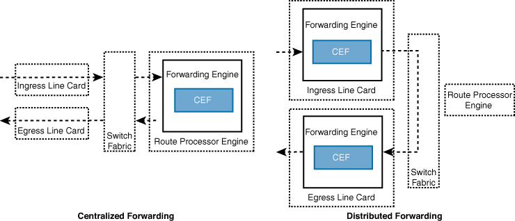
Figure 1-7 Centralized Versus Distributed Forwarding Architectures
Software CEF
Software CEF, also known as the software Forwarding Information Base, consists of the following components:
Forwarding Information Base: The FIB is built directly from the routing table and contains the next-hop IP address for each destination in the network. It keeps a mirror image of the forwarding information contained in the IP routing table. When a routing or topology change occurs in the network, the IP routing table is updated, and these changes are reflected in the FIB. CEF uses the FIB to make IP destination prefix-based switching decisions.
Adjacency table: The adjacency table, also known as the Adjacency Information Base (AIB), contains the directly connected next-hop IP addresses and their corresponding next-hop MAC addresses, as well as the egress interface’s MAC address. The adjacency table is populated with data from the ARP table or other Layer 2 protocol tables.
Figure 1-8 illustrates how the CEF table is built from the routing table. First, the FIB is built from the routing table. The 172.16.10.0/24 prefix is a static route with a next hop of 10.40.40.254, which is dependent upon the 10.40.40.0/24 prefix learned via OSPF. The adjacency pointer in the FIB for the 172.16.10.0/24 entry is exactly the same IP address OSPF uses for the 10.40.40.0/24 prefix (10.10.10.254). The adjacency table is then built using the ARP table and cross-referencing the MAC address with the MAC address table to identify the outbound interface.

Figure 1-8 CEF Switching
Upon receipt of an IP packet, the FIB is checked for a valid entry. If an entry is missing, it is a “glean” adjacency in CEF, which means the packet should go to the CPU because CEF is unable to handle it. Valid FIB entries continue processing by checking the adjacency table for each packet’s destination IP address. Missing adjacency entries invoke the ARP process. Once ARP is resolved, the complete CEF entry can be created.
As part of the packet forwarding process, the packet’s headers are rewritten. The router overwrites the destination MAC address of a packet with the next-hop router’s MAC address from the adjacency table, overwrites the source MAC address with the MAC address of the outgoing Layer 3 interface, decrements the IP time-to-live (TTL) field, recomputes the IP header checksum, and finally delivers the packet to the next-hop router.
Hardware CEF
The ASICs in hardware-based routers are expensive to design, produce, and troubleshoot. ASICs allow for very high packet rates, but the trade-off is that they are limited in their functionality because they are hardwired to perform specific tasks. The routers are equipped with NPUs that are designed to overcome the inflexibility of ASICs. Unlike ASICs, NPUs are programmable, and their firmware can be changed with relative ease.
The main advantage of the distributed forwarding architectures is that the packet throughput performance is greatly improved by offloading the packet switching responsibilities to the line cards. Packet switching in distributed architecture platforms is done via distributed CEF (dCEF), which is a mechanism in which the CEF data structures are downloaded to forwarding ASICs and the CPUs of all line cards so that they can participate in packet switching; this allows for the switching to be done at the distributed level, thus increasing the packet throughput of the router.
Stateful Switchover
Routers specifically designed for high availability include hardware redundancy, such as dual power supplies and route processors (RPs). An RP is responsible for learning the network topology and building the route table (RIB). An RP failure can trigger routing protocol adjacencies to reset, resulting in packet loss and network instability. During an RP failure, it may be more desirable to hide the failure and allow the router to continue forwarding packets using the previously programmed CEF table entries rather than temporarily drop packets while waiting for the secondary RP to reestablish the routing protocol adjacencies and rebuild the forwarding table.
Stateful switchover (SSO) is a redundancy feature that allows a Cisco router with two RPs to synchronize router configuration and control plane state information. The process of mirroring information between RPs is referred to as checkpointing. SSO-enabled routers always checkpoint line card operation and Layer 2 protocol states. During a switchover, the standby RP immediately takes control and prevents basic problems such as interface link flaps. However, Layer 3 packet forwarding is disrupted without additional configuration. The RP switchover triggers a routing protocol adjacency flap that clears the route table. When the routing table is cleared, the CEF entries are purged, and traffic is no longer routed until the network topology is relearned and the forwarding table is reprogrammed. Enabling nonstop forwarding (NSF) or nonstop routing (NSR) high availability capabilities informs the router(s) to maintain the CEF entries for a short duration and continue forwarding packets through an RP failure until the control plane recovers.
SDM Templates
The capacity of MAC addresses that a switch needs compared to the number of routes that it holds depends on where it is deployed in the network. The memory used for TCAM tables is limited and statically allocated during the bootup sequence of the switch. When a section of a hardware resource is full, all processing overflow is sent to the CPU, which seriously impacts the performance of the switch.
The allocation ratios between the various TCAM tables are stored and can be modified with Switching Database Manager (SDM) templates. Multiple Cisco switches exist, and the SDM template can be configured on Catalyst 9000 switches with the global configuration command sdm prefer {vlan | advanced}. The switch must then be restarted with the reload command.
Table 1-2 shows the approximate number of resources available per template. This could vary based on the switch platform or software version in use. These numbers are typical for Layer 2 and IPv4 features. Some features, such as IPv6, use twice the entry size, which means only half as many entries can be created.
Table 1-2 Approximate Number of Feature Resources Allowed by Templates
Resource |
Advanced |
VLAN |
Number of VLANs |
4094 |
4094 |
Unicast MAC addresses |
32,000 |
32,000 |
Overflow unicast MAC addresses |
512 |
512 |
IGMP groups and multicast routes |
4000 |
4000 |
Overflow IGMP groups and multicast routes |
512 |
512 |
Directly connected routes |
16,000 |
16,000 |
Indirectly connected IP hosts |
7000 |
7000 |
Policy-based routing access control entries (ACEs) |
1024 |
0 |
QoS classification ACEs |
3000 |
3000 |
Security ACEs |
3000 |
3000 |
NetFlow ACEs |
1024 |
1024 |
Input Microflow policer ACEs |
256,000 |
0 |
Output Microflow policer ACEs |
256,000 |
0 |
FSPAN ACEs |
256 |
256 |
Control Plane Entries |
512 |
512 |
The current SDM template can viewed with the command show sdm prefer, as demonstrated in Example 1-17.
Example 1-17 Viewing the Current SDM Template
SW1# show sdm prefer
Showing SDM Template Info

This is the Advanced (high scale) template.
  Number of VLANs:                                 4094
  Unicast MAC addresses:                           32768
  Overflow Unicast MAC addresses:                  512
  IGMP and Multicast groups:                       4096
  Overflow IGMP and Multicast groups:              512
  Directly connected routes:                       16384
  Indirect routes:                                 7168
  Security Access Control Entries:                 3072
  QoS Access Control Entries:                      2560
  Policy Based Routing ACEs:                       1024
  Netflow ACEs:                                    768
  Wireless Input Microflow policer ACEs:           256
  Wireless Output Microflow policer ACEs:          256
  Flow SPAN ACEs:                                  256
  Tunnels:                                         256
  Control Plane Entries:                           512
  Input Netflow flows:                             8192
  Output Netflow flows:                            16384
  SGT/DGT and MPLS VPN entries:                    3840
  SGT/DGT and MPLS VPN Overflow entries:           512
These numbers are typical for L2 and IPv4 features.
Some features such as IPv6, use up double the entry size;
so only half as many entries can be created.
Exam Preparation Tasks
As mentioned in the section “How to Use This Book” in the Introduction, you have a couple of choices for exam preparation: the exercises here, Chapter 30, “Final Preparation,” and the exam simulation questions in the Pearson Test Prep Software Online.
Review All Key Topics
Review the most important topics in the chapter, noted with the Key Topic icon in the outer margin of the page. Table 1-3 lists these key topics and the page number on which each is found.
Table 1-3 Key Topics for Chapter 1
Key Topic Element |
Description |
Page |
Paragraph |
Collision domain |
|
Paragraph |
Virtual LANs (VLANs) |
|
Section |
Access ports |
|
Section |
Trunk ports |
|
Paragraph |
Content addressable memory |
|
Paragraph |
Address resolution protocol (ARP) |
|
Paragraph |
Packet Routing |
|
Paragraph |
IP address assignment |
|
Section |
Process switching |
|
Section |
Cisco Express Forwarding (CEF) |
|
Section |
Ternary content addressable memory |
|
Section |
Software CEF |
|
Section |
SDM templates |
Complete Tables and Lists from Memory
There are no memory tables in this chapter.
Define Key Terms
Define the following key terms from this chapter and check your answers in the Glossary:
Address Resolution Protocol (ARP)
Cisco Express Forwarding (CEF)
content addressable memory (CAM)
Forwarding Information Base (FIB)
Routing Information Base (RIB)
Use the Command Reference to Check Your Memory
Table 1-4 lists the important commands from this chapter. To test your memory, cover the right side of the table with a piece of paper, read the description on the left side, and see how much of the command you can remember.
Table 1-4 Command Reference
Task |
Command Syntax |
Define a VLAN |
vlan vlan-id name vlanname |
Configure an interface as a trunk port |
switchport mode trunk |
Configure an interface as an access port assigned to a specific VLAN |
switchport mode access switchport access {vlan vlan-id | name name} |
Configure a static MAC address entry |
mac address-table static mac-address vlan vlan-id interface interface-id |
Clear MAC addresses from the MAC address table |
clear mac address-table dynamic [{address mac-address | interface interface-id | vlan vlan-id}] |
Assign an IPv4 address to an interface |
ip address ip-address subnet-mask |
Assign a secondary IPv4 address to an interface |
ip address ip-address subnet-mask secondary |
Assign an IPv6 address to an interface |
ipv6 address ipv6-address/prefix-length |
Modify the SDM database |
sdm prefer {vlan | advanced} |
Display the interfaces that are configured as a trunk port and all the VLANs that they permit |
show interfaces trunk |
Display the list of VLANs and their associated ports |
show vlan [{brief | id vlan-id | name vlanname | summary}] |
Display the MAC address table for a switch |
show mac address-table [address mac-address | dynamic | vlan vlan-id] |
Display the current interface state, including duplex, speed, and link state |
show interfaces |
Display the Layer 2 configuration information for a specific switchport |
show interfaces interface-id switchport |
Display the ARP table |
show ip arp [mac-address | ip-address | vlan vlan-id | interface-id]. |
Displays the IP interface table |
show ip interface [brief | interface-id | vlan vlan-id] |
Display the IPv6 interface table |
show ipv6 interface [brief | interface-id | vlan vlan-id] |
References in This Chapter
Bollapragada, Vijay, Russ White, and Curtis Murphy. Inside Cisco IOS Software Architecture. (ISBN-13: 9781587058165).
Stringfield, Nakia, Russ White, and Stacia McKee. Cisco Express Forwarding. (ISBN-13: 9780133433340).