Chapter 4. Multiple Spanning Tree Protocol
This chapter covers the following subject:
Multiple Spanning Tree Protocol: This section examines the benefits and operationsof MST.
This chapter completes the section on spanning tree by explaining Multiple Spanning Tree Protocol (MST). MST is the one of three STP modes supported on Catalyst switches.
“Do I Know This Already?” Quiz
The “Do I Know This Already?” quiz allows you to assess whether you should read the entire chapter. If you miss no more than one of these self-assessment questions, you might want to move ahead to the “Exam Preparation Tasks” section. Table 4-1 lists the major headings in this chapter and the “Do I Know This Already?” quiz questions covering the material in those headings so you can assess your knowledge of these specific areas. The answers to the “Do I Know This Already?” quiz appear in Appendix A, “Answers to the ‘Do I Know This Already?’ Quiz Questions.”
Table 4-1 “Do I Know This Already?” Foundation Topics Section-to-Question Mapping
Foundation Topics Section |
Questions |
Multiple Spanning Tree Protocol |
1–7 |
1. Which of the following issues does MST solve? (Choose two.)
Enables traffic load balancing for specific VLANs
Reduces the CPU and memory resources needed for environments with large numbers of VLANs
Overcomes MAC address table scaling limitations for environments with large numbers of devices
Detects issues with cabling that transmits data in one direction
Prevents unauthorized switches from attaching to the Layer 2 domain
2. With MST, VLANs are directly associated with ______.
areas
regions
instances
switches
3. What do CST and 802.1D have in common?
They support only one topology.
They support multiple topologies.
They allow for load balancing of traffic across different VLANs.
They provide switch authentication so that inter-switch connectivity can occur.
4. True or false: The MST root bridge advertises the VLAN-to-instance mappings to all other MST switches.
True
False
5. True or false: The MST configuration version is locally significant.
True
False
6. True or false: The MST topology can be tuned for root bridge placement, just like PVST+ and RSTP.
True
False
7. MST regions can interact with PVST+/RSTP in which of the following ways? (Choose two.)
The MST region is the root bridge for all VLANs.
The MST region is the root bridge for some VLANs.
The PVST+/RSTP topology is the root bridge for all VLANs.
The PVST+/RSTP topology is the root bridge for some VLANs.
Answers to the “Do I Know This Already?” quiz:
1 A, B
2 C
3 A
4 B
5 B
6 A
7 A, C
Foundation Topics
Multiple Spanning Tree Protocol
The original 802.1D standard, much like the 802.1Q standard, supported only one STP instance for an entire switch network. In this situation, referred to as Common Spanning Tree (CST), all VLANs used the same topology, which meant it was not possible to load share traffic across links by blocking for specific VLANs on one link and then blocking for other VLANs on alternate links.
Figure 4-1 shows four VLANs sharing the same topology. All network traffic from SW2 toward SW3 must traverse through SW1. If VLAN 4 contained devices only on SW2 and SW3, the topology could not be tuned with traffic going directly between the two switches.

Figure 4-1 Common Spanning Tree Instance (CST) Topology
Cisco developed the Per-VLAN Spanning Tree (PVST) protocol to allow for an STP topology for each VLAN. With PVST, the root bridge can be placed on a different switch or can cost ports differently, on a VLAN-by-VLAN basis. This allows for a link to be blocked for one VLAN and forwarding for another.
Figure 4-2 demonstrates how all three switches maintain an STP topology for each of the 4 VLANs. If 10 more VLANs were added to this environment, the switches would have to maintain 14 STP topologies. With the third STP instance for VLAN 3, the blocking port moves to the SW1 ← → SW3 link due to STP tuning to address the needs of the traffic between SW2 (where servers attach) and SW3 (where clients attach). On the fourth STP instance, devices on VLAN 4 reside only on SW2 and SW3, so moving the blocking port to the SW2 ← → SW1 link allows for optimal traffic flow.

Figure 4-2 Per-VLAN Spanning Tree (PVST) Topologies
Now, in environments with thousands of VLANs, maintaining an STP state for all the VLANs can become a burden to the switch’s processors. The switches must process BPDUs for every VLAN, and when a major trunk link fails, they must compute multiple STP operations to converge the network. MST provides a blended approach by mapping one or multiple VLANs onto a single STP tree, called an MST instance (MSTI).
Figure 4-3 shows how all three switches maintain three STP topologies for 4 VLANs. If 10 more VLANs were added to this environment, then the switches would maintain three STP topologies if they aligned to one of the three existing MSTIs. VLANs 1 and 2 correlate to one MSTI, VLAN 3 to a second MSTI, and VLAN 4 to a third MSTI.

Figure 4-3 MST Topologies
A grouping of MST switches with the same high-level configuration is known as an MST region. MST incorporates mechanisms that make an MST region appear as a single virtual switch to external switches as part of a compatibility mechanism.
Figure 4-4 demonstrates the concept further, showing the actual STP topology beside the topology perceived by devices outside the MST region. Normal STP operations would calculate SW5 blocking the port toward SW3 by using the operations explained in Chapter 2, “Spanning Tree Protocol.” But special notice should go toward SW3 blocking the port toward SW1. Normally SW3 would mark that port as an RP, but because it sees the topology from a larger collective, it is blocking that port rather than blocking the port between SW2 and SW3. In addition, SW7 is blocking the port toward the MST region. SW7 and SW5 are two physical hops away from the root bridge, but SW5 is part of the MST region virtual switch and appears to be one hop away, from SW7’s perspective. That is why SW7 places its port into a blocking state.
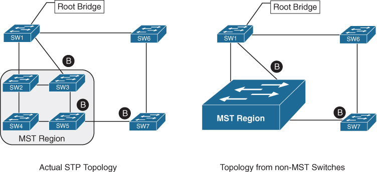
Figure 4-4 Operating Functions Within an MST Region
MST Instances (MSTIs)
MST uses a special STP instance called the internal spanning tree (IST), which is always the first instance, instance 0. The IST runs on all switch port interfaces for switches in the MST region, regardless of the VLANs associated with the ports. Additional information about other MSTIs is included (nested) in the IST BPDU that is transmitted throughout the MST region. This enables the MST to advertise only one set of BPDUs, minimizing STP traffic regardless of the number of instances while providing the necessary information to calculate the STP for other MSTIs.
MST Configuration
MST is configured using the following process:
Step 1. Define MST as the spanning tree protocol with the command spanning-tree mode mst.
Step 2. (Optional) Define the MST instance priority, using one of two methods:
spanning-tree mst instance-number priority priority
The priority is a value between 0 and 61,440, in increments of 4096.
spanning-tree mst instance-number root {primary | secondary}[diameter diameter]
The primary keyword sets the priority to 24,576, and the secondary keyword sets the priority to 28,672.
Step 3. Associate VLANs to an MST instance. By default, all VLANs are associated to the MST 0 instance. The MST configuration submode must be entered with the command spanning-tree mst configuration. Then the VLANs are assigned to a different MST instance with the command instance instance-number vlan vlan-id.
Step 4. Specify the mst version number. The MST version number must match for all switches in the same MST region. The MST version number is configured with the submode configuration command revision version.
Step 5. (Optional) Define the MST region name. MST regions are recognized by switches that share a common name. By default, a region name is an empty string. The MST region name is set with the command name mst-region-name.
Example 4-1 demonstrates the MST configuration on SW1. MST instance 2 contains VLAN 99, MST instance 1 contains VLANs 10 and 20, and MST instance 0 contains all the other VLANs.
Example 4-1 Sample MST Configuration on SW1
SW1(config)# spanning-tree mode mst
SW1(config)# spanning-tree mst 0 root primary
SW1(config)# spanning-tree mst 1 root primary
SW1(config)# spanning-tree mst 2 root primary
SW1(config)# spanning-tree mst configuration
SW1(config-mst)# name ENTERPRISE_CORE
SW1(config-mst)# revision 2
SW1(config-mst)# instance 1 vlan 10,20
SW1(config-mst)# instance 2 vlan 99
The command show spanning-tree mst configuration provides a quick verification of the MST configuration on a switch. Example 4-2 shows the output. Notice that MST instance 0 contains all the VLANs except for VLANs 10, 20, and 99, regardless of whether those VLANs are configured on the switch. MST instance 1 contains VLAN 10 and 20, and MST instance 2 contains only VLAN 99.
Example 4-2 Verifying the MST Configuration
SW2# show spanning-tree mst configuration
Name      [ENTERPRISE_CORE]
Revision  2     Instances configured 3

Instance  Vlans mapped
--------  ---------------------------------------------------------------------
0         1-9,11-19,21-98,100-4094
1         10,20
2         9
MST Verification
The relevant spanning tree information can be obtained with the command show spanning-tree. However, the VLAN numbers are not shown, and the MST instance is provided instead. In addition, the priority value for a switch is the MST instance plus the switch priority. Example 4-3 shows the output of this command.
Example 4-3 Brief Review of MST Status
SW1# show spanning-tree
! Output omitted for brevity
! Spanning Tree information for Instance 0 (All VLANs but 10,20, and 99)
MST0
  Spanning tree enabled protocol mstp
  Root ID    Priority    24576
             Address     0062.ec9d.c500
             This bridge is the root
             Hello Time   2 sec  Max Age 20 sec  Forward Delay 15 sec

  Bridge ID  Priority    24576  (priority 0 sys-id-ext 0)
             Address     0062.ec9d.c500
             Hello Time   2 sec  Max Age 20 sec  Forward Delay 15 sec

Interface           Role Sts Cost      Prio.Nbr Type
------------------- ---- --- --------- -------- --------------------------------
Gi1/0/2             Desg FWD 20000     128.2    P2p
Gi1/0/3             Desg FWD 20000     128.3    P2p

! Spanning Tree information for Instance 1 (VLANs 10 and 20)
MST1
  Spanning tree enabled protocol mstp
  Root ID    Priority    24577
             Address     0062.ec9d.c500
             This bridge is the root
             Hello Time   2 sec  Max Age 20 sec  Forward Delay 15 sec

  Bridge ID  Priority    24577  (priority 24576 sys-id-ext 1)
             Address     0062.ec9d.c500
             Hello Time   2 sec  Max Age 20 sec  Forward Delay 15 sec

Interface           Role Sts Cost      Prio.Nbr Type
------------------- ---- --- --------- -------- --------------------------------
Gi1/0/2             Desg FWD 20000     128.2    P2p
Gi1/0/3             Desg FWD 20000     128.3    P2p

! Spanning Tree information for Instance 0 (VLAN 30)
MST2
  Spanning tree enabled protocol mstp
  Root ID    Priority    24578
             Address     0062.ec9d.c500
             This bridge is the root
             Hello Time   2 sec  Max Age 20 sec  Forward Delay 15 sec

  Bridge ID  Priority    24578  (priority 24576 sys-id-ext 2)
             Address     0062.ec9d.c500
             Hello Time   2 sec  Max Age 20 sec  Forward Delay 15 sec

Interface           Role Sts Cost      Prio.Nbr Type
------------------- ---- --- --------- -------- --------------------------------
Gi1/0/2             Desg FWD 20000     128.2    P2p
Gi1/0/3             Desg FWD 20000     128.3    P2p
A consolidated view of the MST topology table is displayed with the command show spanning-tree mst [instance-number]. The optional instance-number can be included to restrict the output to a specific instance. The command is shown in Example 4-4. Notice that the VLANs are displayed next to the MST instance, which simplifies troubleshooting.
Example 4-4 Granular View of MST Topology
SW1# show spanning-tree mst
! Output omitted for brevity

##### MST0    vlans mapped:   1-9,11-19,21-98,100-4094
Bridge        address 0062.ec9d.c500  priority      0     (0 sysid 0)
Root          this switch for the CIST
Operational   hello time 2 , forward delay 15, max age 20, txholdcount 6
Configured    hello time 2 , forward delay 15, max age 20, max hops    20

Interface                        Role Sts Cost      Prio.Nbr Type
----------------                 ---- --- --------- -------- --------------------------
Gi1/0/2                          Desg FWD 20000     128.2    P2p
Gi1/0/3                          Desg FWD 20000     128.3    P2p

##### MST1    vlans mapped:   10,20
Bridge        address 0062.ec9d.c500  priority      24577 (24576 sysid 1)
Root          this switch for MST1

Interface                        Role Sts Cost      Prio.Nbr Type
----------------                 ---- --- --------- -------- --------------------------
Gi1/0/2                          Desg FWD 20000     128.2    P2p
Gi1/0/3                          Desg FWD 20000     128.3    P2p

##### MST2    vlans mapped:   99
Bridge        address 0062.ec9d.c500  priority      24578 (24576 sysid 2)
Root          this switch for MST2

Interface                        Role Sts Cost      Prio.Nbr Type
----------------                 ---- --- --------- -------- --------------------------
Gi1/0/2                          Desg FWD 20000     128.2    P2p
Gi1/0/3                          Desg FWD 20000     128.3    P2p
The specific MST settings are viewed for a specific interface with the command showspanning-tree mst interface interface-id, as shown in Example 4-5. Notice that the output in this example includes additional information about optional STP features such as BPDU filter and BPDU guard.
Example 4-5 Viewing Interface-Specific MST Settings
SW2# show spanning-tree mst interface gigabitEthernet 1/0/1

GigabitEthernet1/0/1 of MST0 is root forwarding
Edge port: no             (default)        port guard : none        (default)
Link type: point-to-point (auto)           bpdu filter: disable     (default)
Boundary : internal                        bpdu guard : disable     (default)
Bpdus sent 17, received 217

Instance Role Sts Cost      Prio.Nbr Vlans mapped
-------- ---- --- --------- -------- -------------------------------
0        Root FWD 20000     128.1    1-9,11-19,21-98,100-4094
1        Root FWD 20000     128.1    10,20
2        Root FWD 20000     128.1    99
MST Tuning
MST supports the tuning of port cost and port priority. The interface configuration command spanning-tree mst instance-number cost cost sets the interface cost. Example 4-6 demonstrates the configuration of SW3’s Gi1/0/1 port being modified to a cost of 1 and verification of the interface cost before and after the change.
Example 4-6 Changing the MST Interface Cost
SW3# show spanning-tree mst 0
! Output omitted for brevity
Interface                        Role Sts Cost      Prio.Nbr Type
----------------                 ---- --- --------- -------- --------------------
Gi1/0/1                          Root FWD 20000     128.1    P2p
Gi1/0/2                          Altn BLK 20000     128.2    P2p
Gi1/0/5                          Desg FWD 20000     128.5    P2p
SW3# configure term
Enter configuration commands, one per line. End with CNTL/Z.
SW3(config)# interface gi1/0/1
SW3(config-if)# spanning-tree mst 0 cost 1
SW3# show spanning-tree mst 0
! Output omitted for brevity
Interface                        Role Sts Cost      Prio.Nbr Type
----------------                 ---- --- --------- -------- ---------------------
Gi1/0/1                          Root FWD 1         128.1    P2p
Gi1/0/2                          Desg FWD 20000     128.2    P2p
Gi1/0/5                          Desg FWD 20000     128.5    P2p
The interface configuration command spanning-tree mst instance-number port-priority priority sets the interface priority. Example 4-7 demonstrates the configuration of SW4’s Gi1/0/5 port being modified to a priority of 64 and verification of the interface priority before and after the change.
Example 4-7 Changing the MST Interface Priority
SW4# show spanning-tree mst 0
! Output omitted for brevity
##### MST0    vlans mapped:   1-9,11-19,21-98,100-4094
Interface                        Role Sts Cost      Prio.Nbr Type
----------------                 ---- --- --------- -------- --------------------
Gi1/0/2                          Root FWD 20000     128.2    P2p
Gi1/0/5                          Desg FWD 20000     128.5    P2p
Gi1/0/6                          Desg FWD 20000     128.6    P2p
SW4# configure term
Enter configuration commands, one per line. End with CNTL/Z.
SW4(config)# interface gi1/0/5
SW4(config-if)# spanning-tree mst 0 port-priority 64
SW4# show spanning-tree mst 0
! Output omitted for brevity
##### MST0    vlans mapped:   1-9,11-19,21-98,100-4094
Interface                        Role Sts Cost      Prio.Nbr Type
----------------                 ---- --- --------- -------- --------------------
Gi1/0/2                          Root FWD 20000     128.2    P2p
Gi1/0/5                          Desg FWD 20000      64.5    P2p
Gi1/0/6                          Desg FWD 20000     128.6    P2p
Common MST Misconfigurations
There are two common misconfigurations within the MST region that network engineers should be aware of:
VLAN assignment to the IST
Trunk link pruning
These scenarios are explained in the following sections.
VLAN Assignment to the IST
Remember that the IST operates across all links in the MST region, regardless of the VLAN assigned to the actual port. The IST topology may not correlate to the access layer and might introduce a blocking port that was not intentional.
Figure 4-5 presents a sample topology in which VLAN 10 is assigned to the IST, and VLAN 20 is assigned to MSTI 1. SW1 and SW2 contain two network links between them, with VLAN 10 and VLAN20. It appears as if traffic between PC-A and PC-B would flow across the Gi1/0/2 interface, as it is an access port assigned to VLAN 10. However, all interfaces belong to the IST instance. SW1 is the root bridge, and all of its ports are designated ports (DPs), so SW2 must block either Gi1/0/1 or Gi1/0/2. SW2 blocks Gi1/0/2, based on the port identifier from SW1, which is Gi1/0/2. So now SW2 is blocking the Gi1/0/2 for the IST instance, which is the instance that VLAN 10 is mapped to.

Figure 4-5 Understanding the IST Topology
There are two solutions for this scenario:
Move VLAN 10 to an MSTI instance other than the IST. If you do this, the switches will build a topology based on the links in use by that MSTI.
Allow the VLANs associated with the IST on all interswitch (trunk) links.
Trunk Link Pruning
Pruning of VLANs on a trunk link is a common practice for load balancing. However, it is important that pruning of VLANs does not occur for VLANs in the same MST on different network links.
Figure 4-6 presents a sample topology in which VLAN 10 and VLAN 20 are throughout the entire topology. A junior network engineer has pruned VLANs on the trunk links between SW1 to SW2 and SW1 to SW3 to help load balance traffic. Shortly after implementing the change, users attached to SW1 and SW3 cannot talk to the servers on SW2. This is because while the VLANs on the trunk links have changed, the MSTI topology has not.
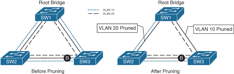
Figure 4-6 Trunk Link Pruning
A simple rule to follow is to only prune all the VLANs in the same MSTI for a trunk link.
MST Region Boundary
The topology for all the MST instances is contained within the IST, which operates internally to the MST region. An MST region boundary is any port that connects to a switch that is in a different MST region or that connects to 802.1D or 802.1W BPDUs.
MSTIs never interact outside the region. MST switches can detect PVST+ neighbors at MST region boundaries. Propagating the CST (derived from the IST) at the MST region boundary involves a feature called the PVST simulation mechanism.
The PVST simulation mechanism sends out PVST+ (and includes RSTP, too) BPDUs (one for each VLAN), using the information from the IST. To be very explicit, this requires a mapping of one topology (IST) to multiple VLANs (VLANs toward the PVST link). The PVST simulation mechanism is required because PVST+/RSTP topologies do not understand the IST BPDU structure.
When the MST boundary receives PVST+ BPDUs, it does not map the VLANs to the appropriate MSTIs. Instead, the MST boundary maps the PVST+ BPDU from VLAN 1 to the IST instance. The MST boundary engages the PVST simulation mechanism only when it receives a PVST BPDU on a port.
There are two design considerations when integrating an MST region with a PVST+/RSTP environment: The MST region is the root bridge or the MST region is not a root bridge for any VLAN. These scenarios are explained in the following sections.
MST Region as the Root Bridge
Making the MST region the root bridge ensures that all region boundary ports flood the same IST instance BPDU to all the VLANs in the PVST topology. Making the IST instance more preferable than any other switch in the PVST+ topology enables this design. The MST region appears as a single entity, and the PVST+ switches detect the alternate link and place it into a blocking state.
Figure 4-7 shows the IST instance as the root bridge for all VLANs. SW1 and SW2 advertise multiple superior BPDUs for each VLAN toward SW3, which is operating as a PVST+ switch. SW3 is responsible for blocking ports.

Figure 4-7 MST Region as the Root
MST Region Not a Root Bridge for Any VLAN
In this scenario, the MST region boundary ports can only block or forward for all VLANs. Remember that only the VLAN 1 PVST BPDU is used for the IST and that the IST BPDU is a one-to-many translation of IST BPDUs to all PVST BPDUs There is not an option to load balance traffic because the IST instance must remain consistent.
If an MST switch detects a better BPDU for a specific VLAN on a boundary port, the switch will use BPDU guard to block this port. The port will then be placed into a root inconsistent state. While this may isolate downstream switches, it is done to ensure a loop-free topology; this is called the PVST simulation check.
Exam Preparation Tasks
As mentioned in the section “How to Use This Book” in the Introduction, you have a couple of choices for exam preparation: the exercises here, Chapter 30, “Final Preparation,” and the exam simulation questions in the Pearson Test Prep Software Online.
Review All Key Topics
Review the most important topics in the chapter, noted with the Key Topic icon in the outer margin of the page. Table 4-2 lists these key topics and the page number on which each is found.
Table 4-2 Key Topics for Chapter 4
Key Topic Element |
Description |
Page |
Section |
Multiple Spanning Tree Protocol |
|
Paragraph |
MST instance |
|
Paragraph |
MST region |
|
Paragraph |
Internal spanning tree (IST) |
|
Section |
MST region boundary |
Complete Tables and Lists from Memory
There are no memory tables in this chapter.
Define Key Terms
Define the following key terms from this chapter and check your answers in the Glossary:
Use the Command Reference to Check Your Memory
Table 4-3 lists the important commands from this chapter. To test your memory, cover the right side of the table with a piece of paper, read the description on the left side, and see how much of the command you can remember.
Table 4-3 Command Reference
Task |
Command Syntax |
Configure the switch for a basic MST region that includes all VLANS and the version number 1 |
spanning-tree mode mst spanning-tree mst configuration instance 0 vlan 1-4094 revision 1 |
Modify a switch’s MSTI priority or make it the root bridge for the MSTI |
spanning-tree mst instance-number priority priority OR spanning-tree mst instance-number root {primary | secondary}[diameter diameter] |
Specify additional VLANs to an MSTI |
spanning-tree mst configuration instance instance-number vlan vlan-id |
Change the MST version number |
spanning-tree mst configuration revision version |
Change the port cost for a specific MSTI |
spanning-tree mst instance-number cost cost |
Change the port priority for a specific MSTI |
spanning-tree mst instance-number port-priority priority |
Display the MST configuration |
show spanning-tree mst configuration |
Verify the MST switch status |
show spanning-tree mst [instance-number] |
View the STP topology for the MST |
show spanning-tree mst interface interface-id |