Chapter 7. EIGRP
This chapter covers the following subjects:
EIGRP Fundamentals: This section explains how EIGRP establishes a neighbor adjacency with other routers and how routes are exchanged with other routers.
Path Metric Calculation: This section explains how EIGRP calculates the path metric to identify the best and alternate loop-free paths.
Failure Detection and Timers: This section explains how EIGRP detects the absence of a neighbor and the convergence process.
Route Summarization: This section explains the logic and configuration related to summarizing routes on a router.
Enhanced Interior Gateway Routing Protocol (EIGRP) is an enhanced distance vector routing protocol commonly used in enterprises networks. Initially, it was a Cisco proprietary protocol, but it was released to the Internet Engineering Task Force (IETF) through RFC 7868, which was ratified in May 2016.
This chapter explains the underlying mechanics of the EIGRP routing protocol, the path metric calculations, and the failure detection mechanisms and techniques to optimize the operations of the routing protocol.
“Do I Know This Already?” Quiz
The “Do I Know This Already?” quiz allows you to assess whether you should read the entire chapter. If you miss no more than one of these self-assessment questions, you might want to move ahead to the “Exam Preparation Tasks” section. Table 7-1 lists the major headings in this chapter and the “Do I Know This Already?” quiz questions covering the material in those headings so you can assess your knowledge of these specific areas. The answers to the “Do I Know This Already?” quiz appear in Appendix A, “Answers to the ‘Do I Know This Already?’ Quiz Questions.”
Table 7-1 “Do I Know This Already?” Foundation Topics Section-to-Question Mapping
Foundation Topics Section |
Questions |
EIGRP Fundamentals |
1–5 |
Path Metric Calculation |
6–7 |
Failure Detection and Timers |
8–10 |
EIGRP Route Summarization |
11 |
1. EIGRP uses the protocol number _______ to identify its packets.
87
88
89
90
2. EIGRP uses _______ packet types for inter-router communication.
three
four
five
six
seven
3. What is an EIGRP successor?
The next-hop router for the path with the lowest path metric for a destination prefix
The path with the lowest metric for a destination prefix
The router selected to maintain the EIGRP adjacencies for a broadcast network
A route that satisfies the feasibility condition where the reported distance is less than the feasible distance
4. Which of the following attributes does the EIGRP topology table contain? (Choose all that apply.)
destination network prefix
hop count
total path delay
maximum path bandwidth
list of EIGRP neighbors
5. Which of the following destination addresses does EIGRP use when feasible? (Choose two.)
IP address 224.0.0.9
IP address 224.0.0.10
IP address 224.0.0.8
MAC address 01:00:5E:00:00:0A
MAC address 0C:15:C0:00:00:01
6. Which value can be modified on a router to manipulate the path taken by EIGRP but avoid having impacts on other routing protocols, such as OSPF?
interface bandwidth
interface MTU
interface delay
interface priority
7. EIGRP uses a reference bandwidth of ________ with the default metrics.
100 Mbps
1 Gbps
10 Gbps
40 Gbps
8. The default EIGRP hello timer for a high-speed interfaces is ______.
1 second
5 seconds
10 seconds
20 seconds
30 seconds
60 seconds
9. When a path has been identified using EIGRP and in a stable fashion, the route is considered ______.
passive
dead
active
alive
10. How does an EIGRP router indicate that a path computation is required for a specific route?
EIGRP sends out an EIGRP update packet with the topology change notification flag set.
EIGRP sends out an EIGRP update packet with a metric value of zero.
EIGRP sends out an EIGRP query with the delay set to infinity.
EIGRP sends a route withdrawal, notifying other neighbors to remove the route from the topology table.
11. True or false: EIGRP summarization occurs for network prefixes as it crosses all network interfaces.
True
False
Answers to the “Do I Know This Already?” quiz:
1 B
2 C
3 A
4 A, B, C, E
5 B, D
6 C
7 C
8 B
9 A
10 C
11 B
Foundation Topics
EIGRP Fundamentals
EIGRP overcomes the deficiencies of other distance vector routing protocols like RIP with features such as unequal-cost load balancing, support for networks 255 hops away, and rapid convergence features. EIGRP uses a diffusing update algorithm (DUAL) to identify network paths and enable fast convergence using precalculated loop-free backup paths. Most distance vector routing protocols use hop count as the metric for routing decisions. However, using hop count for path selection does not take into account link speed and total delay. EIGRP adds to the route selection algorithm logic that uses factors outside hop count.
Autonomous Systems
A router can run multiple EIGRP processes. Each process operates under the context of an autonomous system, which represents a common routing domain. Routers within the same domain use the same metric calculation formula and exchange routes only with members of the same autonomous system. An EIGRP autonomous system should not be confused with a Border Gateway Protocol (BGP) autonomous system.
In Figure 7-1, EIGRP autonomous system (AS) 100 consists of R1, R2, R3, and R4, and EIGRP AS 200 consists of R3, R5, and R6. Each EIGRP process correlates to a specific autonomous system and maintains an independent EIGRP topology table. R1 does not have knowledge of routes from AS 200 because it is different from its own autonomous system, AS 100. R3 is able to participate in both autonomous systems and by default does not transfer routes learned from one autonomous system into a different autonomous system.
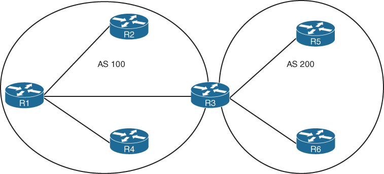
Figure 7-1 EIGRP Autonomous Systems
EIGRP Terminology
This section explains some of the core concepts of EIGRP and the path selection process in EIGRP. Figure 7-2 is the reference topology for this section; it shows R1 calculating the best path and alternative loop-free paths to the 10.4.4.0/24 network. Each value in parentheses represents a particular link’s calculated metric for a segment, based on bandwidth and delay.
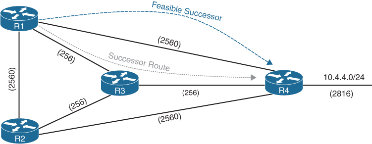
Figure 7-2 EIGRP Reference Topology
Table 7-2 lists some key terms, definitions, and their correlation to Figure 7-2.
Table 7-2 EIGRP Terminology
Term |
Definition |
Successor route |
The route with the lowest path metric to reach a destination. The successor route for R1 to reach 10.4.4.0/24 on R4 is R1→R3→R4. |
Successor |
The first next-hop router for the successor route. The successor for 10.4.4.0/24 is R3. |
Feasible distance (FD) |
The metric value for the lowest-metric path to reach a destination. The feasible distance is calculated locally using the formula shown in the “Path Metric Calculation” section, later in this chapter. The FD calculated by R1 for the 10.4.4.0/24 network is 3328 (that is, 256+256+2816). |
Reported distance (RD) |
The distance reported by a router to reach a prefix. The reported distance value is the feasible distance for the advertising router. R3 advertises the 10.4.4.0/24 prefix with an RD of 3072. R4 advertises the 10.4.4.0/24 to R1 and R2 with an RD of 2816. |
Feasibility condition |
A condition under which, for a route to be considered a backup route, the reported distance received for that route must be less than the feasible distance calculated locally. This logic guarantees a loop-free path. |
Feasible successor |
A route that satisfies the feasibility condition and is maintained as a backup route. The feasibility condition ensures that the backup route is loop free. The route R1→R4 is the feasible successor because the RD 2816 is lower than the FD 3328 for the R1→R3→R4 path. |
Topology Table
EIGRP contains a topology table that makes it different from a “true” distance vector routing protocol. EIGRP’s topology table is a vital component to DUAL and contains information to identify loop-free backup routes. The topology table contains all the network prefixes advertised within an EIGRP autonomous system. Each entry in the table contains the following:
Network prefix
EIGRP neighbors that have advertised that prefix
Metrics from each neighbor (for example, reported distance, hop count)
Values used for calculating the metric (for example, load, reliability, total delay, minimum bandwidth)
Figure 7-3 shows the topology table for R1 in Figure 7-1. This section focuses on the 10.4.4.0/24 network in explaining the topology table.
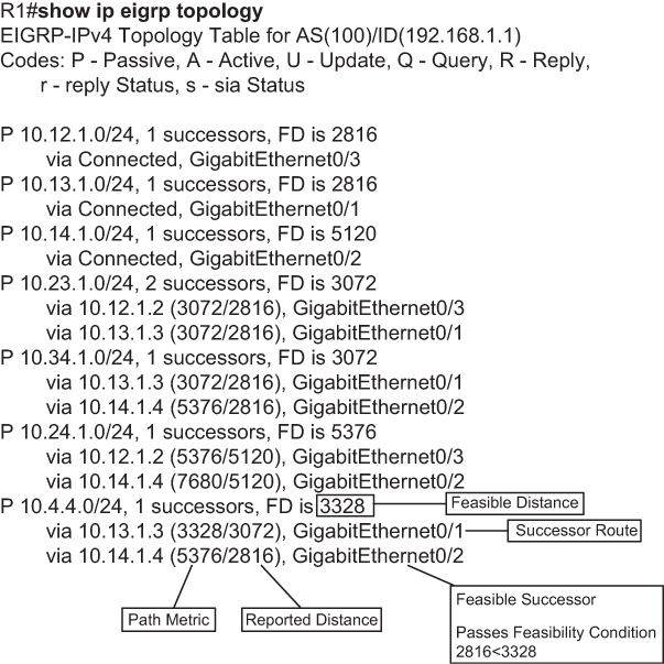
Figure 7-3 EIGRP Topology Output
Upon examining the network 10.4.4.0/24, notice that R1 calculates an FD of 3328 for the successor route. The successor (upstream router) advertises the successor route with an RD of 3072. The second path entry has a metric of 5376 and has an RD of 2816. Because 2816 is less than 3072, the second entry passes the feasibility condition, which means the second entry is classified as the feasible successor for the prefix.
The 10.4.4.0/24 route is passive (P), which means the topology is stable. During a topology change, routes go into an active (A) state when computing a new path.
EIGRP Neighbors
EIGRP neighbors exchange the entire routing table when forming an adjacency, and they advertise only incremental updates as topology changes occur within a network. The neighbor adjacency table is vital for tracking neighbor status and the updates sent to each neighbor.
EIGRP uses five different packet types to communicate with other routers, as shown in Table 7-3. EIGRP uses its own IP number (88); it uses multicast packets where possible and unicast packets when necessary. Communication between routers is done with multicast, using the group address 224.0.0.10 when possible.
Table 7-3 EIGRP Packet Types
Type |
Packet Name |
Function |
1 |
Hello |
Used for discovery of EIGRP neighbors and for detecting when a neighbor is no longer available |
2 |
Request |
Used to get specific information from one or more neighbors |
3 |
Update |
Used to transmit routing and reachability information with other EIGRP neighbors |
4 |
Query |
Sent out to search for another path during convergence |
5 |
Reply |
Sent in response to a query packet |
Path Metric Calculation
Metric calculation is a critical component for any routing protocol. EIGRP uses multiple factors to calculate the metric for a path. Metric calculation uses bandwidth and delay by default, but it can include interface load and reliability, too. The formula shown in Figure 7-4 illustrates the EIGRP classic metric formula.
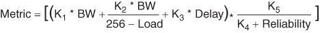
Figure 7-4 EIGRP Classic Metric Formula
EIGRP uses K values to define which factors the formula uses and the associated impact of a factor when calculating the metric. A common misconception is that K values directly apply to bandwidth, load, delay, or reliability; this is not accurate. For example, K1 and K2 both reference bandwidth (BW).
BW represents the slowest link in the path scaled to a 10 Gbps link (107). Link speed is collected from the configured interface bandwidth on an interface. Delay is the total measure of delay in the path, measured in tens of microseconds (μs).
The EIGRP formula is based on the IGRP metric formula, except the output is multiplied by 256 to change the metric from 24 bits to 32 bits. Taking these definitions into consideration, the formula for EIGRP is shown in Figure 7-5.
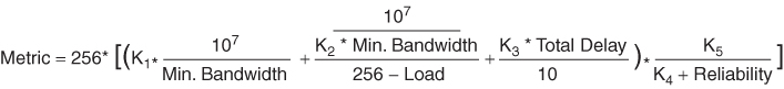
Figure 7-5 EIGRP Classic Metric Formula with Definitions
By default, K1 and K3 have the value 1, and K2, K4, and K5 are set to 0. Figure 7-6 places default K values into the formula and then shows a streamlined version of the formula.

Figure 7-6 EIGRP Classic Metric Formula with Default K Values
The EIGRP update packet includes path attributes associated with each prefix. The EIGRP path attributes can include hop count, cumulative delay, minimum bandwidth link speed, and RD. The attributes are updated each hop along the way, allowing each router to independently identify the shortest path.
Figure 7-7 displays the information in the EIGRP update packets for the 10.1.1.0/24 prefix propagating through the autonomous system. Notice that the hop count increments, minimum bandwidth decreases, total delay increases, and RD changes with each router in the AS.

Figure 7-7 EIGRP Attribute Propagation
Table 7-4 shows some of the common network types, link speeds, delay, and EIGRP metrics, using the streamlined formula from Figure 7-6.
Table 7-4 Default EIGRP Interface Metrics for Classic Metrics
Interface Type |
Link Speed (kbps) |
Delay |
Metric |
Serial |
64 |
20,000 μs |
40,512,000 |
T1 |
1544 |
20,000 μs |
2,170,031 |
Ethernet |
10,000 |
1000 μs |
281,600 |
FastEthernet |
100,000 |
100 μs |
28,160 |
GigabitEthernet |
1,000,000 |
10 μs |
2816 |
10 GigabitEthernet |
10,000,000 |
10 μs |
512 |
Using the topology from Figure 7-2, the metric from R1 and R2 for the 10.4.4.0/24 network can be calculated using the formula in Figure 7-8. The link speed for both routers is 1 Gbps, and the total delay is 30 μs (10 μs for the 10.4.4.0/24 link, 10 μs for the 10.34.1.0/24 link, and 10 μs for the 10.13.1.0/24 link).
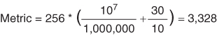
Figure 7-8 EIGRP Classic Metric Formula with Default K Values
Wide Metrics
The original EIGRP specifications measured delay in 10 μs units and bandwidth in kilobytes per second, which did not scale well with higher-speed interfaces. In Table 7-4, notice that the delay is the same for the Gigabit Ethernet and 10-Gigabit Ethernet interfaces.
Example 7-1 provides some metric calculations for common LAN interface speeds. Notice that there is not a differentiation between an 11 Gbps interface and a 20 Gbps interface. The composite metric stays at 256, despite having different bandwidth rates.
Example 7-1 Calculating Metrics for Common LAN Interface Speeds
GigabitEthernet:
Scaled Bandwidth = 10,000,000 / 1000000
Scaled Delay = 10 / 10
Composite Metric = 10 + 1 * 256 = 2816
10 GigabitEthernet:
Scaled Bandwidth = 10,000,000 / 10000000
Scaled Delay = 10 / 10
Composite Metric = 1 + 1 * 256 = 512
11 GigabitEthernet:
Scaled Bandwidth = 10,000,000 / 11000000
Scaled Delay = 10 / 10
Composite Metric = 0 + 1 * 256 = 256
20 GigabitEthernet:
Scaled Bandwidth = 10,000,000 / 20000000
Scaled Delay = 10 / 10
Composite Metric = 0 + 1 * 256 = 256
EIGRP includes support for a second set of metrics, known as wide metrics, that addresses the issue of scalability with higher-capacity interfaces. The original formula referenced in Figure 7-4 refers to EIGRP classic metrics.
Figure 7-9 shows the explicit EIGRP wide metrics formula. Notice that an additional K value (K6) is included that adds an extended attribute to measure jitter, energy, or other future attributes.

Figure 7-9 EIGRP Wide Metrics Formula
Just as EIGRP scaled by 256 to accommodate IGRP, EIGRP wide metrics scale by 65,535 to accommodate higher-speed links. This provides support for interface speeds up to 655 Tbps (65,535 × 107) without any scalability issues. Latency is the total interface delay measured in picoseconds (10-12) instead of measuring in microseconds (10-6). Figure 7-10 displays the updated formula that takes into account the conversions in latency and scalability.
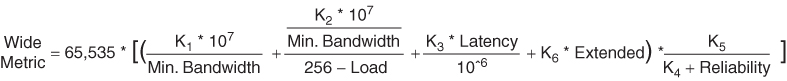
Figure 7-10 EIGRP Wide Metrics Formula with Definitions
Metric Backward Compatibility
EIGRP wide metrics were designed with backward compatibility in mind. With EIGRP wide metrics, K1 and K3 are set to a value of 1, and K2, K4, K5, and K6 are set to 0, which allows backward compatibility because the K value metrics match with classic metrics. As long as K1 through K5 are the same and K6 is not set, the two metrics styles allow adjacency between routers.
EIGRP is able to detect when peering with a router is using classic metrics, and it unscales a metric from the formula in Figure 7-11.

Figure 7-11 Formula for Calculating Unscaled EIGRP Metrics
Load Balancing
EIGRP allows multiple successor routes (using the same metric) to be installed into the RIB. Installing multiple paths into the RIB for the same prefix is called equal-cost multipathing (ECMP).
EIGRP supports unequal-cost load balancing, which allows installation of both successor routes and feasible successors into the EIGRP RIB. EIGRP supports unequal-cost load balancing by changing EIGRP’s variance multiplier. The EIGRP variance value is the feasible distance (FD) for a route multiplied by the EIGRP variance multiplier. Any feasible successor’s FD with a metric below the EIGRP variance value is installed into the RIB. EIGRP installs multiple routes where the FD for the routes is less than the EIGRP multiplier value up to the maximum number of ECMP routes, as discussed earlier.
Dividing the feasible successor metric by the successor route metric provides the variance multiplier. The variance multiplier is a whole number, so any remainders should always round up.
Using Figure 7-2 as the example topology and output from the EIGRP topology table in Figure 7-3, the minimum EIGRP variance multiplier can be calculated so that the direct path from R1 to R4 can be installed into the RIB. The FD for the successor route is 3328, and the FD for the feasible successor is 5376. The formula provides a value of about 1.6 and is always rounded up to the nearest whole number to provide an EIGRP variance multiplier of 2. Figure 7-12 displays the calculation.
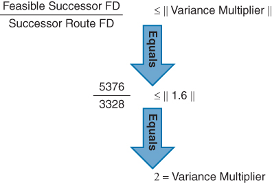
Figure 7-12 EIGRP Variance Multiplier Formula
Example 7-2 provides a brief verification that both paths have been installed into the RIB. Notice that the metrics for the paths are different. One path metric is 3328, and the other path metric is 5376. The traffic share count setting correlates to the ratio of traffic sent across each path.
Example 7-2 Verifying Unequal-Cost Load Balancing
R1# show ip route eigrp | begin Gateway
Gateway of last resort is not set

      10.0.0.0/8 is variably subnetted, 10 subnets, 2 masks
D        10.4.4.0/24 [90/5376] via 10.14.1.4, 00:00:03, GigabitEthernet0/2
                     [90/3328] via 10.13.1.3, 00:00:03, GigabitEthernet0/1
R1# show ip route 10.4.4.0
Routing entry for 10.4.4.0/24
  Known via "eigrp 100", distance 90, metric 3328, type internal
  Redistributing via eigrp 100
  Last update from 10.13.1.3 on GigabitEthernet0/1, 00:00:35 ago
  Routing Descriptor Blocks:
  * 10.14.1.4, from 10.14.1.4, 00:00:35 ago, via GigabitEthernet0/2
      Route metric is 5376, traffic share count is 149
      Total delay is 110 microseconds, minimum bandwidth is 1000000 Kbit
      Reliability 255/255, minimum MTU 1500 bytes
      Loading 1/255, Hops 1
    10.13.1.3, from 10.13.1.3, 00:00:35 ago, via GigabitEthernet0/1
      Route metric is 3328, traffic share count is 240
      Total delay is 30 microseconds, minimum bandwidth is 1000000 Kbit
      Reliability 254/255, minimum MTU 1500 bytes
      Loading 1/255, Hops 2
Failure Detection and Timers
A secondary function for the EIGRP hello packets is to ensure that EIGRP neighbors are still healthy and available. EIGRP hello packets are sent out in intervals determined by the hello timer. The default EIGRP hello timer is 5 seconds, but it is 60 seconds on slow-speed interfaces (T1 or lower).
EIGRP uses a second timer for the hold time, which is the amount of time EIGRP deems the router reachable and functioning. The hold time value defaults to 3 times the hello interval. The default value is 15 seconds, and it is 180 seconds for slow-speed interfaces. The hold time decrements, and upon receipt of a hello packet, the hold time resets and restarts the countdown. If the hold time reaches 0, EIGRP declares the neighbor unreachable and notifies DUAL of a topology change.
Convergence
When a link fails, and the interface protocol moves to a down state, any neighbor attached to that interface moves to a down state, too. When an EIGRP neighbor moves to a down state, path recomputation must occur for any prefix where that EIGRP neighbor was a successor (upstream router).
When EIGRP detects that it has lost its successor for a path, the feasible successor instantly becomes the successor route, providing a backup route. The router sends out an update packet for that path because of the new EIGRP path metrics. Downstream routers run their own DUAL for any impacted prefixes to account for the new EIGRP metrics. It is possible that a change of the successor route or feasible successor may occur upon receipt of new EIGRP metrics from a successor router for a prefix. Figure 7-13 demonstrates such a scenario when the link between R1 and R3 fails.
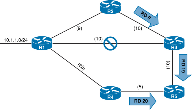
Figure 7-13 EIGRP Topology with Link Failure
R3 installs the feasible successor path advertised from R2 as the successor route. R3 sends an update packet with a new RD of 19 for the 10.1.1.0/24 prefix. R5 receives the update packet from R3 and calculates an FD of 29 for the R1–R2–R3 path to 10.1.1.0/24. R5 compares that path to the one received from R4, which has a path metric of 25. R5 chooses the path via R4 as the successor route.
If a feasible successor is not available for a prefix, DUAL must perform a new route calculation. The route state changes from passive (P) to active (A) in the EIGRP topology table.
The router detecting the topology change sends out query packets to EIGRP neighbors for the route. The query packet includes the network prefix with the delay set to infinity so that other routers are aware that it has gone active. When the router sends the EIGRP query packets, it sets the reply status flag set for each neighbor on a prefix basis.
Upon receipt of a query packet, an EIGRP router does one of the following:
It might reply to the query that the router does not have a route to the prefix.
If the query did not come from the successor for that route, it detects the delay set for infinity but ignores it because it did not come from the successor. The receiving router replies with the EIGRP attributes for that route.
If the query came from the successor for the route, the receiving router detects the delay set for infinity, sets the prefix as active in the EIGRP topology, and sends out a query packet to all downstream EIGRP neighbors for that route.
The query process continues from router to router until a router establishes the query boundary. A query boundary is established when a router does not mark the prefix as active, meaning that it responds to a query as follows:
It says it does not have a route to the prefix.
It replies with EIGRP attributes because the query did not come from the successor.
When a router receives a reply for every downstream query that was sent out, it completes the DUAL, changes the route to passive, and sends a reply packet to any upstream routers that sent a query packet to it. Upon receiving the reply packet for a prefix, the reply packet is notated for that neighbor and prefix. The reply process continues upstream for the queries until the first router’s queries are received.
Figure 7-14 shows a topology where the link between R1 and R2 has failed.
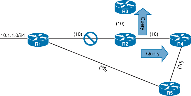
Figure 7-14 EIGRP Convergence Topology
The following steps are processed in order from the perspective of R2 calculating a new route to the 10.1.1.0/24 network:
Step 1. R2 detects the link failure. R2 does not have a feasible successor for the route, sets the 10.1.1.0/24 prefix as active, and sends queries to R3 and R4.
Step 2. R3 receives the query from R2 and processes the Delay field that is set to infinity. R3 does not have any other EIGRP neighbors and sends a reply to R2 saying that a route does not exists.
R4 receives the query from R2 and processes the Delay field that is set to infinity. Because the query was received by the successor, and a feasible successor for the prefix does not exist, R4 marks the route as active and sends a query to R5.
Step 3. R5 receives the query from R4 and detects that the Delay field is set to infinity. Because the query was received by a nonsuccessor and a successor exists on a different interface, a reply for the 10.4.4.0/24 network is sent back to R2 with the appropriate EIGRP attributes.
Step 4. R4 receives R5’s reply, acknowledges the packet, and computes a new path. Because this is the last outstanding query packet on R4, R4 sets the prefix as passive. With all queries satisfied, R4 responds to R2’s query with the new EIGRP metrics.
Step 5. R2 receives R4’s reply, acknowledges the packet, and computes a new path. Because this is the last outstanding query packet on R4, R2 sets the prefix as passive.
Route Summarization
EIGRP works well with minimal optimizations. Scalability of an EIGRP autonomous system depends on summarization. As the size of an EIGRP autonomous system increases, convergence may take longer. Scaling an EIGRP topology requires summarizing routes in a hierarchical fashion.
EIGRP summarizes network prefixes on an interface basis. A summary aggregate is configured for the EIGRP interface. Prefixes within the summary aggregate are suppressed, and the summary aggregate prefix is advertised in lieu of the original prefixes. The summary aggregate prefix is not advertised until a prefix matches it. Interface-specific summarization can be performed in any portion of the network topology. In addition to shrinking the routing tables of all the routers, summarization creates a query boundary and shrinks the query domain when a route goes active during convergence.
Figure 7-15 illustrates the concept of EIGRP summarization. Without summarization, R2 advertises the 172.16.1.0/24, 172.16.3.0/24, 172.16.12.0/24, and 172.16.23.0/24 networks toward R4. R2 can summarize these network prefixes to the summary aggregate 172.16.0.0/16 prefix so that only one advertisement is sent to R4.

Figure 7-15 EIGRP Summarization
Exam Preparation Tasks
As mentioned in the section “How to Use This Book” in the Introduction, you have a couple of choices for exam preparation: the exercises here, Chapter 30, “Final Preparation,” and the exam simulation questions in the Pearson Test Prep Software Online.
Review All Key Topics
Review the most important topics in the chapter, noted with the Key Topic icon in the outer margin of the page. Table 7-5 lists these key topics and the page number on which each is found.
Table 7-5 Key Topics for Chapter 7
Key Topic Element |
Description |
Page |
EIGRP Terminology |
||
Section |
Topology table |
|
EIGRP Packet Types |
||
EIGRP Attribute Propagation |
||
EIGRP Wide Metrics Formula |
||
Paragraph |
EIGRP unequal-cost load balancing |
|
Section |
Convergence |
|
Paragraph |
Active route state |
Complete Tables and Lists from Memory
Print a copy of Appendix B, “Memory Tables” (found on the companion website), or at least the section for this chapter, and complete the tables and lists from memory. Appendix C, “Memory Tables Answer Key,” also on the companion website, includes completed tables and lists you can use to check your work.
Define Key Terms
Define the following key terms from this chapter, and check your answers in the glossary:
References in This Chapter
Edgeworth, Brad, Foss, Aaron, Garza Rios, Ramiro. IP Routing on Cisco IOS, IOS XE, and IOS XR. Indianapolis: Cisco Press: 2014.
RFC 7838, Cisco8217;s Enhanced Interior Gateway Routing Protocol (EIGRP), by D. Savage, J. Ng, S. Moore, D. Slice, P. Paluch, and R. White. http://tools.ietf.org/html/rfc7868, May 2016.
Cisco IOS Software Configuration Guides. http://www.cisco.com.