Chapter 2. Basic IPv4 Access Control Lists
This chapter covers the following exam topics:
5.0 Security Fundamentals
5.6 Configure and verify access control lists
IPv4 access control lists (ACL) give network engineers the ability to program a filter into a router. Each router, on each interface, for both the inbound and outbound direction, can enable a different ACL with different rules. Each ACL’s rules tell the router which packets to discard and which to allow through.
This chapter discusses the basics of IPv4 ACLs, and in particular, one type of IP ACL: standard numbered IP ACLs. Standard numbered ACLs use simple logic, matching on the source IP address field only, and use a configuration style that references the ACL using a number. This chapter sets out to help you learn this simpler type of ACL first. The next chapter, titled, “Advanced IPv4 Access Control Lists,” completes the discussion by describing other types of IP ACLs. The other types of ACLs use features that build on the concepts you learn in this chapter, but with more complexity and additional configuration options.
“Do I Know This Already?” Quiz
Take the quiz (either here or use the PTP software) if you want to use the score to help you decide how much time to spend on this chapter. The letter answers are listed at the bottom of the page following the quiz. Appendix C, found both at the end of the book as well as on the companion website, includes both the answers and explanations. You can also find both answers and explanations in the PTP testing software.
Table 2-1 “Do I Know This Already?” Foundation Topics Section-to-Question Mapping
Foundation Topics Section |
Questions |
IP Access Control List Basics |
1 |
Standard Numbered IPv4 ACLs |
2–5 |
Practice Applying Standard IP ACLs |
6 |
1. Barney is a host with IP address 10.1.1.1 in subnet 10.1.1.0/24. Which of the following are things that a standard IP ACL could be configured to do? (Choose two answers.)
Match the exact source IP address.
Match IP addresses 10.1.1.1 through 10.1.1.4 with one access-list command without matching other IP addresses.
Match all IP addresses in Barney’s subnet with one access-list command without matching other IP addresses.
Match only the packet’s destination IP address.
2. Which of the following answers list a valid number that can be used with standard numbered IP ACLs? (Choose two answers.)
1987
2187
187
87
3. Which of the following wildcard masks is most useful for matching all IP packets in subnet 10.1.128.0, mask 255.255.255.0?
0.0.0.0
0.0.0.31
0.0.0.240
0.0.0.255
0.0.15.0
0.0.248.255
4. Which of the following wildcard masks is most useful for matching all IP packets in subnet 10.1.128.0, mask 255.255.240.0?
0.0.0.0
0.0.0.31
0.0.0.240
0.0.0.255
0.0.15.255
0.0.248.255
5. ACL 1 has three statements, in the following order, with address and wildcard mask values as follows: 1.0.0.0 0.255.255.255, 1.1.0.0 0.0.255.255, and 1.1.1.0 0.0.0.255. If a router tried to match a packet sourced from IP address 1.1.1.1 using this ACL, which ACL statement does a router consider the packet to have matched?
First
Second
Third
Implied deny at the end of the ACL
6. Which of the following access-list commands matches all packets sent from hosts in subnet 172.16.4.0/23?
access-list 1 permit 172.16.0.5 0.0.255.0
access-list 1 permit 172.16.4.0 0.0.1.255
access-list 1 permit 172.16.5.0
access-list 1 permit 172.16.5.0 0.0.0.127
Answers to the “Do I Know This Already?” quiz:
1 A, C
2 A, D
3 D
4 E
5 A
6 B
Foundation Topics
IPv4 Access Control List Basics
IPv4 access control lists (IP ACL) give network engineers a way to identify different types of packets. To do so, the ACL configuration lists values that the router can see in the IP, TCP, UDP, and other headers. For example, an ACL can match packets whose source IP address is 1.1.1.1, or packets whose destination IP address is some address in subnet 10.1.1.0/24, or packets with a destination port of TCP port 23 (Telnet).
IPv4 ACLs perform many functions in Cisco routers, with the most common use as a packet filter. Engineers can enable ACLs on a router so that the ACL sits in the forwarding path of packets as they pass through the router. After it is enabled, the router considers whether each IP packet will either be discarded or allowed to continue as if the ACL did not exist.
However, ACLs can be used for many other IOS features as well. As an example, ACLs can be used to match packets for applying Quality of Service (QoS) features. QoS allows a router to give some packets better service, and other packets worse service. For example, packets that hold digitized voice need to have very low delay, so ACLs can match voice packets, with QoS logic in turn forwarding voice packets more quickly than data packets.
This first section introduces IP ACLs as used for packet filtering, focusing on these aspects of ACLs: the locations and direction in which to enable ACLs, matching packets by examining headers, and taking action after a packet has been matched.
ACL Location and Direction
Cisco routers can apply ACL logic to packets at the point at which the IP packets enter an interface, or the point at which they exit an interface. In other words, the ACL becomes associated with an interface and for a direction of packet flow (either in or out). That is, the ACL can be applied inbound to the router, before the router makes its forwarding (routing) decision, or outbound, after the router makes its forwarding decision and has determined the exit interface to use.
The arrows in Figure 2-1 show the locations at which you could filter packets flowing left to right in the topology. For example, imagine that you wanted to allow packets sent by host A to server S1, but to discard packets sent by host B to server S1. Each arrowed line represents a location and direction at which a router could apply an ACL, filtering the packets sent by host B.
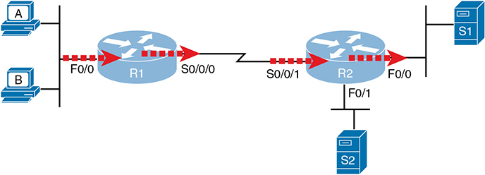
Figure 2-1 Locations to Filter Packets from Hosts A and B Going Toward Server S1
The four arrowed lines in the figure point out the location and direction for the router interfaces used to forward the packet from host B to server S1. In this particular example, those interfaces and direction are inbound on R1’s F0/0 interface, outbound on R1’s S0/0/0 interface, inbound on R2’s S0/0/1 interface, and outbound on R2’s F0/0 interface. If, for example, you enabled an ACL on R2’s F0/1 interface, in either direction, that ACL could not possibly filter the packet sent from host B to server S1, because R2’s F0/1 interface is not part of the route from B to S1.
In short, to filter a packet, you must enable an ACL on an interface that processes the packet, in the same direction the packet flows through that interface.
When enabled, the router then processes every inbound or outbound IP packet using that ACL. For example, if enabled on R1 for packets inbound on interface F0/0, R1 would compare every inbound IP packet on F0/0 to the ACL to decide that packet’s fate: to continue unchanged or to be discarded.
Matching Packets
When you think about the location and direction for an ACL, you must already be thinking about what packets you plan to filter (discard), and which ones you want to allow through. To tell the router those same ideas, you must configure the router with an IP ACL that matches packets. Matching packets refers to how to configure the ACL commands to look at each packet, listing how to identify which packets should be discarded and which should be allowed through.
Each IP ACL consists of one or more configuration commands, with each command listing details about values to look for inside a packet’s headers. Generally, an ACL command uses logic like “look for these values in the packet header, and if found, discard the packet.” (The action could instead be to allow the packet, rather than discard.) Specifically, the ACL looks for header fields you should already know well, including the source and destination IP addresses, plus TCP and UDP port numbers.
For example, consider an example with Figure 2-2, in which you want to allow packets from host A to server S1, but to discard packets from host B going to that same server. The hosts all now have IP addresses, and the figure shows pseudocode for an ACL on R2. Figure 2-2 also shows the chosen location to enable the ACL: inbound on R2’s S0/0/1 interface.

Figure 2-2 Pseudocode to Demonstrate ACL Command-Matching Logic
Figure 2-2 shows a two-line ACL in a rectangle at the bottom, with simple matching logic: both statements just look to match the source IP address in the packet. When enabled, R2 looks at every inbound IP packet on that interface and compares each packet to those two ACL commands. Packets sent by host A (source IP address 10.1.1.1) are allowed through, and those sourced by host B (source IP address 10.1.1.2) are discarded.
Taking Action When a Match Occurs
When using IP ACLs to filter packets, only one of two actions can be chosen. The configuration commands use the keywords deny and permit, and they mean (respectively) to discard the packet or to allow it to keep going as if the ACL did not exist.
This book focuses on using ACLs to filter packets, but IOS uses ACLs for many more features. Those features typically use the same matching logic. However, in other cases, the deny or permit keywords imply some other action.
Types of IP ACLs
Cisco IOS has supported IP ACLs since the early days of Cisco routers. Beginning with the original standard numbered IP ACLs in the early days of IOS, which could enable the logic shown earlier around Figure 2-2, Cisco has added many ACL features, including the following:
Standard numbered ACLs (1–99)
Extended numbered ACLs (100–199)
Additional ACL numbers (1300–1999 standard, 2000–2699 extended)
Named ACLs
Improved editing with sequence numbers
This chapter focuses solely on standard numbered IP ACLs, while the next chapter discusses the other three primary categories of IP ACLs. Briefly, IP ACLs will be either numbered or named in that the configuration identifies the ACL either using a number or a name. ACLs will also be either standard or extended, with extended ACLs having much more robust abilities in matching packets. Figure 2-3 summarizes the big ideas related to categories of IP ACLs.
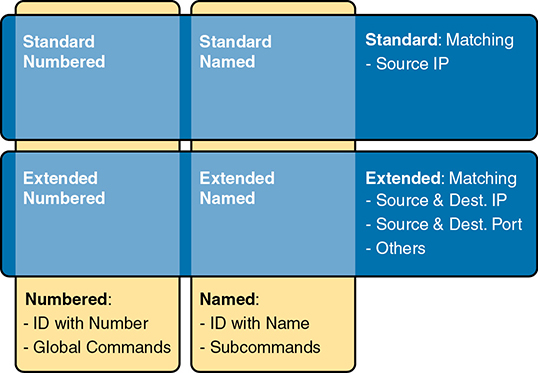
Figure 2-3 Comparisons of IP ACL Types
Standard Numbered IPv4 ACLs
The title of this section serves as a great introduction, if you can decode what Cisco means by each specific word. This section is about a type of Cisco filter (ACL) that matches only the source IP address of the packet (standard), is configured to identify the ACL using numbers rather than names (numbered), and looks at IPv4 packets.
This section examines the particulars of standard numbered IP ACLs. First, it examines the idea that one ACL is a list and what logic that list uses. Following that, the text closely looks at how to match the source IP address field in the packet header, including the syntax of the commands. This section ends with a complete look at the configuration and verification commands to implement standard ACLs.
List Logic with IP ACLs
A single ACL is both a single entity and, at the same time, a list of one or more configuration commands. As a single entity, the configuration enables the entire ACL on an interface, in a specific direction, as shown earlier in Figure 2-1. As a list of commands, each command has different matching logic that the router must apply to each packet when filtering using that ACL.
When doing ACL processing, the router processes the packet, compared to the ACL, as follows:
ACLs use first-match logic. Once a packet matches one line in the ACL, the router takes the action listed in that line of the ACL and stops looking further in the ACL.
To see exactly what that means, consider the example built around Figure 2-4. The figure shows an example ACL 1 with three lines of pseudocode. This example applies ACL 1 on R2’s S0/0/1 interface, inbound (the same location as in earlier Figure 2-2).
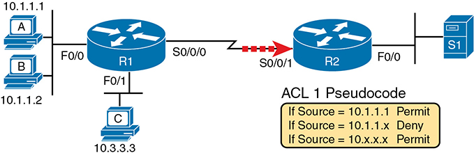
Figure 2-4 Backdrop for Discussion of List Process with IP ACLs
Consider the first-match ACL logic for a packet sent by host A to server S1. The source IP address will be 10.1.1.1, and it will be routed so that it enters R2’s S0/0/1 interface, driving R2’s ACL 1 logic. R2 compares this packet to the ACL, matching the first item in the list with a permit action. So this packet should be allowed through, as shown in Figure 2-5, on the left.
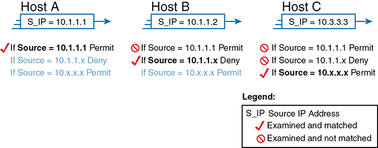
Figure 2-5 ACL Items Compared for Packets from Hosts A, B, and C in Figure 2-4
Next, consider a packet sent by host B, source IP address 10.1.1.2. When the packet enters R2’s S0/0/1 interface, R2 compares the packet to ACL 1’s first statement and does not make a match (10.1.1.1 is not equal to 10.1.1.2). R2 then moves to the second statement, which requires some clarification. The ACL pseudocode, back in Figure 2-4, shows 10.1.1.x, which is meant to be shorthand that any value can exist in the last octet. Comparing only the first three octets, R2 decides that this latest packet does have a source IP address that begins with the first three octets 10.1.1, so R2 considers that to be a match on the second statement. R2 takes the listed action (deny), discarding the packet. R2 also stops ACL processing on the packet, ignoring the third line in the ACL.
Finally, consider a packet sent by host C, again to server S1. The packet has source IP address 10.3.3.3, so when it enters R2’s S0/0/1 interface and drives ACL processing on R2, R2 looks at the first command in ACL 1. R2 does not match the first ACL command (10.1.1.1 in the command is not equal to the packet’s 10.3.3.3). R2 looks at the second command, compares the first three octets (10.1.1) to the packet source IP address (10.3.3), and still finds no match. R2 then looks at the third command. In this case, the wildcard means ignore the last three octets and just compare the first octet (10), so the packet matches. R2 then takes the listed action (permit), allowing the packet to keep going.
This sequence of processing an ACL as a list happens for any type of IOS ACL: IP, other protocols, standard or extended, named or numbered.
Finally, if a packet does not match any of the items in the ACL, the packet is discarded. The reason is that every IP ACL has a deny all statement implied at the end of the ACL. It does not exist in the configuration, but if a router keeps searching the list, and no match is made by the end of the list, IOS considers the packet to have matched an entry that has a deny action.
Matching Logic and Command Syntax
Standard numbered IP ACLs use the following global command:
access-list {1-99 | 1300-1999} {permit | deny} matching-parameters
Each standard numbered ACL has one or more access-list commands with the same number, any number from the ranges shown in the preceding line of syntax. (One number is no better than the other.) IOS refers to each line in an ACL as an Access Control Entry (ACE), but many engineers just call them ACL statements.
Besides the ACL number, each access-list command also lists the action (permit or deny), plus the matching logic. The rest of this section examines how to configure the matching parameters, which, for standard ACLs, means that you can only match the source IP address or portions of the source IP address using something called an ACL wildcard mask.
Matching the Exact IP Address
To match a specific source IP address, the entire IP address, all you have to do is type that IP address at the end of the command. For example, the previous example uses pseudocode for “permit if source = 10.1.1.1.” The following command configures that logic with correct syntax using ACL number 1:
access-list 1 permit 10.1.1.1
Matching the exact full IP address is that simple.
In earlier IOS versions, the syntax included a host keyword. Instead of simply typing the full IP address, you first typed the host keyword and then the IP address. Note that in later IOS versions, if you use the host keyword, IOS accepts the command but then removes the keyword.
access-list 1 permit host 10.1.1.1
Matching a Subset of the Address with Wildcards
Often, the business goals you want to implement with an ACL do not match a single particular IP address, but rather a range of IP addresses. Maybe you want to match all IP addresses in a subnet. Maybe you want to match all IP addresses in a range of subnets. Regardless, you want to check for more than one IP address in a range of addresses.
IOS allows standard ACLs to match a range of addresses using a tool called a wildcard mask. Note that this is not a subnet mask. The wildcard mask (which this book abbreviates as WC mask) gives the engineer a way to tell IOS to ignore parts of the address when making comparisons, essentially treating those parts as wildcards, as if they already matched.
You can think about WC masks in decimal and in binary, and both have their uses. To begin, think about WC masks in decimal, using these rules:
Decimal 0: The router must compare this octet as normal.
Decimal 255: The router ignores this octet, considering it to already match.
Keeping these two rules in mind, consider Figure 2-6, which demonstrates this logic using three different but popular WC masks: one that tells the router to ignore the last octet, one that tells the router to ignore the last two octets, and one that tells the router to ignore the last three octets.

Figure 2-6 Logic for WC Masks 0.0.0.255, 0.0.255.255, and 0.255.255.255
All three examples in the boxes of Figure 2-6 show two numbers that are clearly different. The WC mask causes IOS to compare only some of the octets, while ignoring other octets. All three examples result in a match, because each wildcard mask tells IOS to ignore some octets. The example on the left shows WC mask 0.0.0.255, which tells the router to treat the last octet as a wildcard, essentially ignoring that octet for the comparison. Similarly, the middle example shows WC mask 0.0.255.255, which tells the router to ignore the two octets on the right. The rightmost case shows WC mask 0.255.255.255, telling the router to ignore the last three octets when comparing values.
To see the WC mask in action, think back to the earlier example related to Figure 2-4 and Figure 2-5. The pseudocode ACL in those two figures used logic that can be created using a WC mask. As a reminder, the logic in the pseudocode ACL in those two figures included the following:
Line 1: Match and permit all packets with a source address of exactly 10.1.1.1.
Line 2: Match and deny all packets with source addresses with first three octets 10.1.1.
Line 3: Match and permit all addresses with first single octet 10.
Figure 2-7 shows the updated version of Figure 2-4, but with the completed, correct syntax, including the WC masks. In particular, note the use of WC mask 0.0.0.255 in the second command, telling R2 to ignore the last octet of the number 10.1.1.0, and the WC mask 0.255.255.255 in the third command, telling R2 to ignore the last three octets in the value 10.0.0.0.
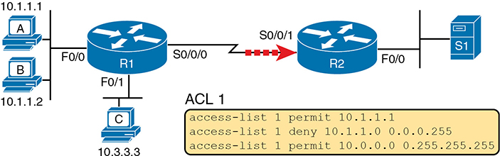
Figure 2-7 Syntactically Correct ACL Replaces Pseudocode from Figure 2-4
Finally, note that when using a WC mask, the access-list command’s loosely defined source parameter should be a 0 in any octets where the WC mask is a 255. IOS will specify a source address to be 0 for the parts that will be ignored, even if nonzero values were configured.
Binary Wildcard Masks
Wildcard masks, as dotted-decimal number (DDN) values, actually represent a 32-bit binary number. As a 32-bit number, the WC mask actually directs the router’s logic bit by bit. In short, a WC mask bit of 0 means the comparison should be done as normal, but a binary 1 means that the bit is a wildcard and can be ignored when comparing the numbers.
Thankfully, for the purposes of CCNA study, and for most real-world applications, you can ignore the binary WC mask. Why? Well, we generally want to match a range of addresses that can be easily identified by a subnet number and mask, whether it be a real subnet, or a summary route that groups subnets together. If you can describe the range of addresses with a subnet number and mask, you can find the numbers to use in your ACL with some simple decimal math, as discussed next.
Finding the Right Wildcard Mask to Match a Subnet
In many cases, an ACL needs to match all hosts in a particular subnet. To match a subnet with an ACL, you can use the following shortcut:
Use the subnet number as the source value in the access-list command.
Use a wildcard mask found by subtracting the subnet mask from 255.255.255.255.
For example, for subnet 172.16.8.0 255.255.252.0, use the subnet number (172.16.8.0) as the address parameter, and then do the following math to find the wildcard mask:
255.255.255.255
– 255.255.252.0
0. 0. 3.255
Continuing this example, a completed command for this same subnet would be as follows:
access-list 1 permit 172.16.8.0 0.0.3.255
The section “Practice Applying Standard IP ACLs” gives you a chance to practice matching subnets when configuring ACLs.
Matching Any/All Addresses
In some cases, you will want one ACL command to match any and all packets that reach that point in the ACL. First, you have to know the (simple) way to match all packets using the any keyword. More importantly, you need to think about when to match any and all packets.
First, to match any and all packets with an ACL command, just use the any keyword for the address. For example, to permit all packets:
access-list 1 permit any
So, when and where should you use such a command? Remember, all Cisco IP ACLs end with an implicit deny any concept at the end of each ACL. That is, if a router compares a packet to the ACL, and the packet matches none of the configured statements, the router discards the packet. Want to override that default behavior? Configure a permit any at the end of the ACL.
You might also want to explicitly configure a command to deny all traffic (for example, access-list 1 deny any) at the end of an ACL. Why, when the same logic already sits at the end of the ACL anyway? Well, the ACL show commands list counters for the number of packets matched by each command in the ACL, but there is no counter for that implicit deny any concept at the end of the ACL. So, if you want to see counters for how many packets are matched by the deny any logic at the end of the ACL, configure an explicit deny any.
Implementing Standard IP ACLs
This chapter has already introduced all the configuration steps in bits and pieces. This section summarizes those pieces as a configuration process. The process also refers to the access-list command, whose generic syntax is repeated here for reference:
access-list access-list-number {deny | permit} source [source-wildcard]
Step 1. Plan the location (router and interface) and direction (in or out) on that interface:
A. Standard ACLs should be placed near to the destination of the packets so that they do not unintentionally discard packets that should not be discarded.
B. Because standard ACLs can only match a packet’s source IP address, identify the source IP addresses of packets as they go in the direction that the ACL is examining.
Step 2. Configure one or more access-list global configuration commands to create the ACL, keeping the following in mind:
A. The list is searched sequentially, using first-match logic.
B. The default action, if a packet does not match any of the access-list commands, is to deny (discard) the packet.
Step 3. Enable the ACL on the chosen router interface, in the correct direction, using the ip access-group number {in | out} interface subcommand.
The rest of this section shows a couple of examples.
Standard Numbered ACL Example 1
The first example shows the configuration for the same requirements demonstrated with Figure 2-4 and Figure 2-5. Restated, the requirements for this ACL are as follows:
Enable the ACL inbound on R2’s S0/0/1 interface.
Permit packets coming from host A.
Deny packets coming from other hosts in host A’s subnet.
Permit packets coming from any other address in Class A network 10.0.0.0.
The original example made no comment about what to do by default, so simply deny all other traffic.
Example 2-1 shows a completed correct configuration, starting with the configuration process, followed by output from the show running-config command.
Example 2-1 Standard Numbered ACL Example 1 Configuration
R2# configure terminal
Enter configuration commands, one per line. End with CNTL/Z.
R2(config)# access-list 1 permit 10.1.1.1
R2(config)# access-list 1 deny 10.1.1.0 0.0.0.255
R2(config)# access-list 1 permit 10.0.0.0 0.255.255.255
R2(config)# interface S0/0/1
R2(config-if)# ip access-group 1 in
R2(config-if)# ^Z
R2# show running-config
! Lines omitted for brevity


access-list 1 permit 10.1.1.1
access-list 1 deny 10.1.1.0 0.0.0.255
access-list 1 permit 10.0.0.0 0.255.255.255
First, pay close attention to the configuration process at the top of the example. Note that the access-list command does not change the command prompt from the global configuration mode prompt, because the access-list command is a global configuration command. Then, compare that to the output of the show running-config command: the details are identical compared to the commands that were added in configuration mode. Finally, make sure to note the ip access-group 1 in command, under R2’s S0/0/1 interface, which enables the ACL logic (both location and direction).
Example 2-2 lists some output from Router R2 that shows information about this ACL. The show ip access-lists command lists details about IPv4 ACLs only, while the show access-lists command lists details about IPv4 ACLs plus any other types of ACLs that are currently configured; for example, IPv6 ACLs.
Example 2-2 ACL show Commands on R2
R2# show ip access-lists
Standard IP access list 1
    10 permit 10.1.1.1 (107 matches)
    20 deny   10.1.1.0, wildcard bits 0.0.0.255 (4 matches)
    30 permit 10.0.0.0, wildcard bits 0.255.255.255 (10 matches)
R2# show access-lists
Standard IP access list 1
    10 permit 10.1.1.1 (107 matches)
    20 deny   10.1.1.0, wildcard bits 0.0.0.255 (4 matches)
    30 permit 10.0.0.0, wildcard bits 0.255.255.255 (10 matches)
R2# show ip interface s0/0/1
Serial0/0/1 is up, line protocol is up
  Internet address is 10.1.2.2/24
  Broadcast address is 255.255.255.255
  Address determined by setup command
  MTU is 1500 bytes
  Helper address is not set
  Directed broadcast forwarding is disabled
  Multicast reserved groups joined: 224.0.0.9
  Outgoing access list is not set
  Inbound access list is 1
! Lines omitted for brevity
The output of these commands shows two items of note. The first line of output in this case notes the type (standard) and the number. If more than one ACL existed, you would see multiple stanzas of output, one per ACL, each with a heading line like this one. Next, these commands list packet counts for the number of packets that the router has matched with each command. For example, 107 packets so far have matched the first line in the ACL.
Finally, the end of the example lists the show ip interface command output. This command lists, among many other items, the number or name of any IP ACL enabled on the interface per the ip access-group interface subcommand.
Standard Numbered ACL Example 2
For the second example, use Figure 2-8, and imagine your boss gives you some requirements hurriedly in the hall. At first, he tells you he wants to filter packets going from the servers on the right toward the clients on the left. Then, he says he wants you to allow access for hosts A, B, and other hosts in their same subnet to server S1, but deny access to that server to the hosts in host C’s subnet. Then, he tells you that, additionally, hosts in host A’s subnet should be denied access to server S2, but hosts in host C’s subnet should be allowed access to server S2—all by filtering packets going right to left only. He then tells you to put the ACL inbound on R2’s F0/0 interface.
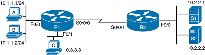
Figure 2-8 Standard Numbered ACL Example 2
If you cull through all the boss’s comments, the requirements might be reduced to the following:
Enable the ACL inbound on R2’s F0/0 interface.
Permit packets from server S1 going to hosts in A’s subnet.
Deny packets from server S1 going to hosts in C’s subnet.
Permit packets from server S2 going to hosts in C’s subnet.
Deny packets from server S2 going to hosts in A’s subnet.
(There was no comment about what to do by default; use the implied deny all default.)
As it turns out, you cannot do everything your boss asked with a standard ACL. For example, consider the obvious command for requirement number 2: access-list 2 permit 10.2.2.1. That permits all traffic whose source IP is 10.2.2.1 (server S1). The very next requirement asks you to filter (deny) packets sourced from that same IP address! Even if you added another command that checked for source IP address 10.2.2.1, the router would never get to it, because routers use first-match logic when searching the ACL. You cannot check both the destination and source IP address, because standard ACLs cannot check the destination IP address.
To solve this problem, you should get a new boss! No, seriously, you have to rethink the problem and change the rules. In real life, you would probably use an extended ACL instead, which lets you check both the source and destination IP address.
For the sake of practicing another standard ACL, imagine your boss lets you change the requirements. First, you will use two outbound ACLs, both on Router R1. Each ACL will permit traffic from a single server to be forwarded onto that connected LAN, with the following modified requirements:
Using an outbound ACL on R1’s F0/0 interface, permit packets from server S1, and deny all other packets.
Using an outbound ACL on R1’s F0/1 interface, permit packets from server S2, and deny all other packets.
Example 2-3 shows the configuration that completes these requirements.
Example 2-3 Alternative Configuration in Router R1
access-list 2 remark This ACL permits server S1 traffic to host A's subnet
access-list 2 permit 10.2.2.1
!
access-list 3 remark This ACL permits server S2 traffic to host C's subnet
access-list 3 permit 10.2.2.2
!
interface F0/0
 ip access-group 2 out
!
interface F0/1
 ip access-group 3 out
As highlighted in the example, the solution with ACL number 2 permits all traffic from server S1, with that logic enabled for packets exiting R1’s F0/0 interface. All other traffic will be discarded because of the implied deny all at the end of the ACL. In addition, ACL 3 permits traffic from server S2, which is then permitted to exit R1’s F0/1 interface. Also, note that the solution shows the use of the access-list remark parameter, which allows you to leave text documentation that stays with the ACL.
Troubleshooting and Verification Tips
Troubleshooting IPv4 ACLs requires some attention to detail. In particular, you have to be ready to look at the address and wildcard mask and confidently predict the addresses matched by those two combined parameters. The upcoming practice problems a little later in this chapter can help prepare you for that part of the work. But a few other tips can help you verify and troubleshoot ACL problems on the exams as well.
First, you can tell if the router is matching packets or not with a couple of tools. Example 2-2 already showed that IOS keeps statistics about the packets matched by each line of an ACL. In addition, if you add the log keyword to the end of an access-list command, IOS then issues log messages with occasional statistics about matches of that particular line of the ACL. Both the statistics and the log messages can be helpful in deciding which line in the ACL is being matched by a packet.
For example, Example 2-4 shows an updated version of ACL 2 from Example 2-3, this time with the log keyword added. The bottom of the example then shows a typical log message, this one showing the resulting match based on a packet with source IP address 10.2.2.1 (as matched with the ACL), to destination address 10.1.1.1.
Example 2-4 Creating Log Messages for ACL Statistics
R1# show running-config
! lines removed for brevity
access-list 2 remark This ACL permits server S1 traffic to host A's subnet
access-list 2 permit 10.2.2.1 log
!
interface F0/0
 ip access-group 2 out

R1#
Feb 4 18:30:24.082: %SEC-6-IPACCESSLOGNP: list 2 permitted 0 10.2.2.1 -> 10.1.1.1, 1
packet
When you troubleshoot an ACL for the first time, before getting into the details of the matching logic, take the time to think about both the interface on which the ACL is enabled and the direction of packet flow. Sometimes, the matching logic is perfect—but the ACL has been enabled on the wrong interface, or for the wrong direction, to match the packets as configured for the ACL.
For example, Figure 2-9 repeats the same ACL shown earlier in Figure 2-7. The first line of that ACL matches the specific host address 10.1.1.1. If that ACL exists on Router R2, placing that ACL as an inbound ACL on R2’s S0/0/1 interface can work, because packets sent by host 10.1.1.1—on the left side of the figure—can enter R2’s S0/0/1 interface. However, if R2 enables ACL 1 on its F0/0 interface, for inbound packets, the ACL will never match a packet with source IP address 10.1.1.1, because packets sent by host 10.1.1.1 will never enter that interface. Packets sent by 10.1.1.1 will exit R2’s F0/0 interface, but never enter it, just because of the network topology.
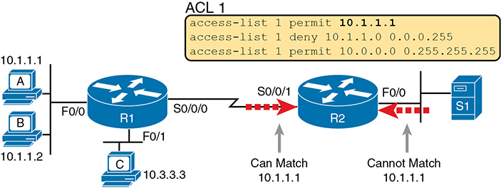
Figure 2-9 Example of Checking the Interface and Direction for an ACL
Practice Applying Standard IP ACLs
Some CCNA topics, like ACLs, simply require more drills and practice than others. ACLs require you to think of parameters to match ranges of numbers, and that of course requires some use of math and some use of processes.
This section provides some practice problems and tips, from two perspectives. First, this section asks you to build one-line standard ACLs to match some packets. Second, this section asks you to interpret existing ACL commands to describe what packets the ACL will match. Both skills are useful for the exams.
Practice Building access-list Commands
In this section, practice getting comfortable with the syntax of the access-list command, particularly with choosing the correct matching logic. These skills will be helpful when reading about extended and named ACLs in the next chapter.
First, the following list summarizes some important tips to consider when choosing matching parameters to any access-list command:
To match a specific address, just list the address.
To match any and all addresses, use the any keyword.
To match based only on the first one, two, or three octets of an address, use the 0.255.255.255, 0.0.255.255, and 0.0.0.255 WC masks, respectively. Also, make the source (address) parameter have 0s in the wildcard octets (those octets with 255 in the wildcard mask).
To match a subnet, use the subnet ID as the source, and find the WC mask by subtracting the DDN subnet mask from 255.255.255.255.
Table 2-2 lists the criteria for several practice problems. Your job: Create a one-line standard ACL that matches the packets. The answers are listed in the section “Answers to Earlier Practice Problems,” later in this chapter.
Table 2-2 Building One-Line Standard ACLs: Practice
Problem |
Criteria |
1 |
Packets from 172.16.5.4 |
2 |
Packets from hosts with 192.168.6 as the first three octets |
3 |
Packets from hosts with 192.168 as the first two octets |
4 |
Packets from any host |
5 |
Packets from subnet 10.1.200.0/21 |
6 |
Packets from subnet 10.1.200.0/27 |
7 |
Packets from subnet 172.20.112.0/23 |
8 |
Packets from subnet 172.20.112.0/26 |
9 |
Packets from subnet 192.168.9.64/28 |
10 |
Packets from subnet 192.168.9.64/30 |
Reverse Engineering from ACL to Address Range
In some cases, you may not be creating your own ACL. Instead, you may need to interpret some existing access-list commands. To answer these types of questions on the exams, you need to determine the range of IP addresses matched by a particular address/wildcard mask combination in each ACL statement.
Under certain assumptions that are reasonable for CCNA certifications, calculating the range of addresses matched by an ACL can be relatively simple. Basically, the range of addresses begins with the address configured in the ACL command. The range of addresses ends with the sum of the address field and the wildcard mask. That’s it.
For example, with the command access-list 1 permit 172.16.200.0 0.0.7.255, the low end of the range is simply 172.16.200.0, taken directly from the command itself. Then, to find the high end of the range, just add this number to the WC mask, as follows:
172.16.200.0
+ 0. 0. 7.255
172.16.207.255
For this last bit of practice, look at the existing access-list commands in Table 2-3. In each case, make a notation about the exact IP address, or range of IP addresses, matched by the command.
Table 2-3 Finding IP Addresses/Ranges Matching by Existing ACLs
Problem |
Commands for Which to Predict the Source Address Range |
1 |
access-list 1 permit 10.7.6.5 |
2 |
access-list 2 permit 192.168.4.0 0.0.0.127 |
3 |
access-list 3 permit 192.168.6.0 0.0.0.31 |
4 |
access-list 4 permit 172.30.96.0 0.0.3.255 |
5 |
access-list 5 permit 172.30.96.0 0.0.0.63 |
6 |
access-list 6 permit 10.1.192.0 0.0.0.31 |
7 |
access-list 7 permit 10.1.192.0 0.0.1.255 |
8 |
access-list 8 permit 10.1.192.0 0.0.63.255 |
Interestingly, IOS lets the CLI user type an access-list command in configuration mode, and IOS will potentially change the address parameter before placing the command into the running-config file. This process of just finding the range of addresses matched by the access-list command expects that the access-list command came from the router, so that any such changes were complete.
The change IOS can make with an access-list command is to convert to 0 any octet of an address for which the wildcard mask’s octet is 255. For example, with a wildcard mask of 0.0.255.255, IOS ignores the last two octets. IOS expects the address field to end with two 0s. If not, IOS still accepts the access-list command, but IOS changes the last two octets of the address to 0s. Example 2-5 shows an example, where the configuration shows address 10.1.1.1, but wildcard mask 0.0.255.255.
Example 2-5 IOS Changing the Address Field in an access-list Command
R2# configure terminal
Enter configuration commands, one per line. End with CNTL/Z.
R2(config)# access-list 21 permit 10.1.1.1 0.0.255.255
R2(config)# ^Z
R2#
R2# show ip access-lists
Standard IP access list 21
    10 permit 10.1.0.0, wildcard bits 0.0.255.255
The math to find the range of addresses relies on the fact that either the command is fully correct or that IOS has already set these address octets to 0, as shown in the example.
Chapter Review
One key to doing well on the exams is to perform repetitive spaced review sessions. Review this chapter’s material using either the tools in the book or interactive tools for the same material found on the book’s companion website. Refer to the “Your Study Plan” element for more details. Table 2-4 outlines the key review elements and where you can find them. To better track your study progress, record when you completed these activities in the second column.
Table 2-4 Chapter Review Tracking
Review Element |
Review Date(s) |
Resource Used |
Review key topics |
|
Book, website |
Review key terms |
|
Book, website |
Repeat DIKTA questions |
|
Book, PTP |
Review command tables |
|
Book |
Review All the Key Topics
Table 2-5 Key Topics for Chapter 2
Key Topic Element |
Description |
Page Number |
Paragraph |
Summary of the general rule of the location and direction for an ACL |
|
Summary of four main categories of IPv4 ACLs in Cisco IOS |
||
Paragraph |
Summary of first-match logic used by all ACLs |
|
List |
Wildcard mask logic for decimal 0 and 255 |
|
List |
Wildcard mask logic to match a subnet |
|
List |
Steps to plan and implement a standard IP ACL |
|
List |
Tips for creating matching logic for the source address field in the access-list command |
Key Terms You Should Know
Additional Practice for This Chapter’s Processes
For additional practice with analyzing subnets, you may do the same set of practice problems using your choice of tools:
Application: Use the two ACL practice exercise applications listed on the companion website.
PDF: Alternatively, practice the same problems found in these apps using online Appendix E, “Practice for Chapter 2: Basic IPv4 Access Control Lists.”
Command References
Tables 2-6 and 2-7 list configuration and verification commands used in this chapter. As an easy review exercise, cover the left column in a table, read the right column, and try to recall the command without looking. Then repeat the exercise, covering the right column, and try to recall what the command does.
Table 2-6 Chapter 2 Configuration Command Reference
Command |
Description |
access-list access-list-number {deny | permit} source [source-wildcard] [log] |
Global command for standard numbered access lists. Use a number between 1 and 99 or 1300 and 1999, inclusive. |
access-list access-list-number remark text |
Command that defines a remark to help you remember what the ACL is supposed to do. |
ip access-group number {in | out} |
Interface subcommand to enable access lists. |
Table 2-7 Chapter 2 EXEC Command Reference
Command |
Description |
show ip interface [type number] |
Includes a reference to the access lists enabled on the interface |
show access-lists [access-list-number | access-list-name] |
Shows details of configured access lists for all protocols |
show ip access-lists [access-list-number | access-list-name] |
Shows IP access lists |
Answers to Earlier Practice Problems
Table 2-8 lists the answers to the problems listed earlier in Table 2-2.
Table 2-8 Building One-Line Standard ACLs: Answers
Problem |
Answers |
1 |
access-list 1 permit 172.16.5.4 |
2 |
access-list 2 permit 192.168.6.0 0.0.0.255 |
3 |
access-list 3 permit 192.168.0.0 0.0.255.255 |
4 |
access-list 4 permit any |
5 |
access-list 5 permit 10.1.200.0 0.0.7.255 |
6 |
access-list 6 permit 10.1.200.0 0.0.0.31 |
7 |
access-list 7 permit 172.20.112.0 0.0.1.255 |
8 |
access-list 8 permit 172.20.112.0 0.0.0.63 |
9 |
access-list 9 permit 192.168.9.64 0.0.0.15 |
10 |
access-list 10 permit 192.168.9.64 0.0.0.3 |
Table 2-9 lists the answers to the problems listed earlier in Table 2-3.
Table 2-9 Address Ranges for Problems in Table 2-3: Answers
Problem |
Address Range |
1 |
One address: 10.7.6.5 |
2 |
192.168.4.0 – 192.168.4.127 |
3 |
192.168.6.0 – 192.168.6.31 |
4 |
172.30.96.0 – 172.30.99.255 |
5 |
172.30.96.0 – 172.30.96.63 |
6 |
10.1.192.0 – 10.1.192.31 |
7 |
10.1.192.0 – 10.1.193.255 |
8 |
10.1.192.0 – 10.1.255.255 |