
3
AWS Networking Services
The odds are 100% that you will be using networking services at AWS. Networking at AWS is called the virtual private cloud, or EC2-VPC. This chapter explores in detail the available networking options for virtual private clouds (VPCs) and how they are set up and configured at AWS. At the end of this chapter, you will have a strong understanding of VPCs, networking services and options available, and understand the necessity of properly planning your networking services.
The reality is that you may need to read this chapter a few times to become comfortable with the networking services at AWS. There are a few changes when setting up and managing networking in the cloud even though the terms might look familiar. In the previous chapter, we looked at the big picture of regions and zones, and edge locations—the bedrock services at AWS that we really can’t touch. Networking at AWS, the subnet is the lowest level we can gain access to, and it’s all at a virtual level. Yes, there is a physical network at AWS, but we don’t get to access it directly. Starting with the lowest point of the stack that we are allowed to control, let’s get into networking.
One of the first configuration questions that will be asked of you when ordering an EC2 instance; AWS WorkSpaces, their hosted VDI solution; or RDS, their hosted database solution is this question: what VPC or what subnet do you want to use? The topics for this chapter include the following:
VPC networking
Subnets and IP address types
Route tables
Security groups and NACLs
VPN connectivity options
Route 53—the domain name system (DNS) service
Questions we will ponder and reflect on for this networking chapter focus on our case study Terra Firma and its human resources customer relationship management (CRM) software system. To recap, the company’s current CRM system was developed in-house several years ago and is running successfully on VMware server images in the corporate data center. Other details include:
Management agrees that the current HR system must be migrated to AWS as soon as possible.
The company’s HR system needs to be able to properly scale to handle the increased demand of upper management.
The human resources system must be available 24 hours a day and needs to be accessed across the Internet and from corporate head and branch offices.
Some of the questions they need to get answered include these:
How many VPCs should Terra Firma consider using?
How many AZs should Terra Firma use to design for failover?
How many subnets should Terra Firma use?
Do the Web servers need public or private IP addresses?
Can we privately access AWS resources from within a VPC?
Are NAT services required?
Compliance rules mandate security at the subnet level. Is that possible at AWS?
VPC Networking
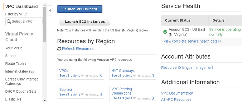
The networking layer at AWS is a VPC, and we generally work with networking services using the VPC console, as shown in Figure 3-1. The official name of a VPC is an EC2-VPC, even if we typically just use the VPC moniker. The EC2 (Elastic Cloud Compute) designation indicates that EC2 instances are usually hosted within a VPC. Each VPC is a logically isolated “data center” where your computer instances and various AWS services reside. Software that can run successfully on a Windows or Linux virtual server can be hosted on EC2 instances hosted in VPCs running as Web/application servers, databases, NAT servers, or any third-party software appliance you can think of.
When you order a VPC, AWS’s job is securing your VPC as a private isolated software data center linked to your AWS account. AWS’s job is to provision, host, and secure the VPC; the rest is up to us. There is also plenty of AWS management going on below the surface of a VPC; your network traffic must be routed and protected based on your network design and needs. In addition, Amazon must ensure the continued separation of your VPC from all other AWS customers. Any failure on Amazon’s end in safeguarding and protecting VPC networks just can’t happen.
There are lots of moving parts and pieces at AWS, which I like to describe as a large toolbox containing a variety of tools and attachments that you can mesh or cobble together any way they suit your needs. Within the VPC “toolbox” are many configurable options, including route tables, public and private subnets, VPN connections, gateways, and private endpoints, to name just a few of the available options. In addition, there are multiple security choices available at every network level allowing you to fully protect your EC2 instances; choices include security groups and network access control lists (ACLs). A VPC also has multiple connectivity options, allowing you to connect your VPC to the Internet, to your own private data center, to other VPCs within your region or outside your region, or to other AWS accounts holders’ VPCs.
Partnering with AWS
Hosting your applications in the Amazon public cloud means you have implicitly accepted to work in partnership with AWS in what is typically defined as a shared security model. AWS has responsibilities of building and securing its cloud infrastructure; this is typically defined as Security of the Cloud. Your responsibility as an AWS customer is to design acceptable security provisions for your applications and data hosted within the AWS cloud. The level of acceptable security provisions is entirely your choice. The definition for the customer’s responsibilities of securing their resources at AWS is called Security in the Cloud. Customers can choose to use any of the managed services and utilities provided to accomplish their deployment and security goals. Within each VPC, your compute instances (EC2) are hosted on subnets that you create in selected availability zones (AZs) within the AWS region you chose to operate within. Although the VPC is a managed service, customers make most of the choices and decisions on their own after AWS carries out the initial creation of the VPC.
Because a VPC is defined as a virtual private network (VPN), it’s easy to forget sometimes that you’re still participating within a shared environment when hosting applications in the AWS cloud. AWS customers all share the private network backbone linking shared compute, storage, and services, as shown in Figure 3-2. Of course, the one issue you don’t want to experience in the AWS cloud is an unexpected loss of privacy.
Amazon’s private global network that hosts all the VPCs has terabytes of networking capacity available. AWS also owns and operates all the fiber connections connecting their data centers, AZs, regions, and edge location equipment together. However, the networking services that are exposed to each customer at AWS are not running on the same network hardware devices that are deployed in your own data centers. Some of the networking service terms we are going to define may also be new to you. And some of the other networking components that are utilized at AWS will hopefully sound familiar—terms like subnets, public and private IP addresses, and route tables. But you will find that your overall design of networking services at AWS will still be different from what you would use on-premise. Hosting hundreds of thousands of customers in a massive shared networking environment means networking can’t be the same as your on-premise network due to the size and scope of Amazon’s overall operation.
Note
If you’re a new customer at AWS, the VPC is the only networking choice currently available for hosting your workloads. There used to be another networking option available at AWS called EC2-Classic. We won’t be spending any time on this older style of networking because you don’t want and can’t access EC2-Classic networking; it hasn’t been available for new customers since December 2013. And you wouldn’t want to use it instead of a VPC. To begin with, EC2-Classic networking was a flat network design that was shared with all other EC2-Classic AWS customers. The EC2-Classic feature set available is quite minimal compared to the expansive options available with a VPC. However, your company may have EC2-Classic networking if it began working with Amazon before 2013.
To Host or to Associate?
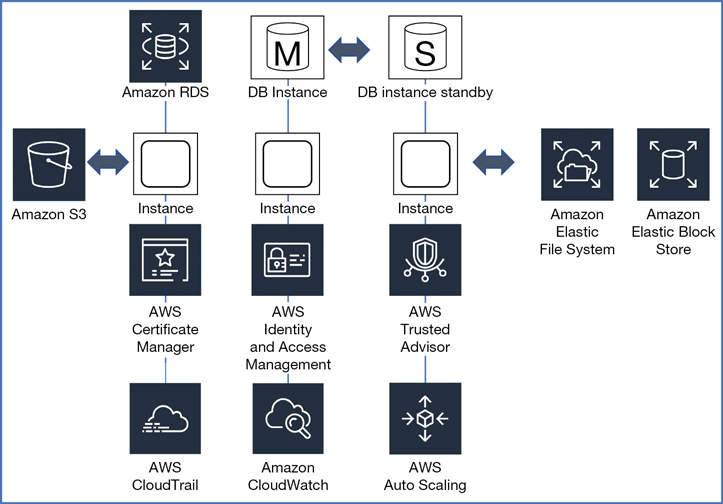
Some services can be hosted within a VPC, and others can be associated to a VPC. There are many additional AWS management and compliance services that you will probably want to use. Some of these services will have relationships with the services and components hosted inside a VPC, but the services themselves are not actually installed in the VPC. AWS services such as AWS Config (a compliance tool) and ELB (Elastic Load Balancing) aren’t installed or hosted within a VPC; instead, they reside on the private or public Amazon network and, once ordered or selected, are then associated or linked to the chosen VPC carrying out their task. Table 3-1 lists several examples of AWS services that are either hosted or associated with a VPC.
Table 3-1 AWS Services That Host or Link to a VPC
Hosted VPC Services |
Associated Services |
|---|---|
EC2 instances |
Trusted Advisor |
Elastic Beanstalk |
AWS Config |
Amazon Redshift |
VPN connections |
ElastiCache |
Auto Scaling |
Amazon EMR |
Elastic load balancing |
Amazon RDS |
S3 |
Amazon Workspaces |
DynamoDB |
The reality is that most of Amazon’s offerings are not actually installed inside a VPC. The primary service hosted in a VPC is the EC2 instance.
What’s Behind the Networking Curtain?
How is it possible to manage thousands of customers who require hosted private networking services? To complicate this reality, customers change their minds all the time. It’s a daunting task. Customers who order a VPC are working within their own private walled garden of virtual networking. The first major concept of networking at AWS is that within each VPC, the networking exposed to each customer is designed and managed at the subnet level—specifically, the Layer 3 subnet address space contained within each availability zone. That’s as deep as we’re going to get in the network stack at AWS. Full stop.
Your on-premise networking environment is probably composed of virtual local area networks (VLANs), Layer 2 networks, and Multiprotocol Label Switching (MPLS) connections. Why does a customer’s exposure to the AWS network then start and end at Layer 3? Because thousands of customers are running on a massively shared network infrastructure, and AWS is running at a scale that far exceeds the scale utilized within your own data centers. As a result, the internal network design offered to each customer needs to be different as well.
AWS is not using VLANs on the internal private network because these technologies cannot scale to the number of customers that Amazon hosts. A VPC also doesn’t use MPLS for communications; however, you may be utilizing MPLS connections when connecting to a VPC using an external Direct Connect connection from your on-premise network to AWS. You can find more details on external VPC connections later in this chapter. If you have worked with public cloud providers for several years, you may have experienced ordering networks with an email request and waiting a few days to get set up; or perhaps you waited just a few hours. Waiting a few hours or even days might be acceptable within your own data center. In the hosted public cloud, however, we demand and get cloud resources instantly. Amazon had to figure out a way to combine scale, automation, and instant gratification, and they did. Ordering a VPC takes seconds; if a VLAN had to be set up for each customer network, the process would ultimately take too much time and, as discussed, not be able to scale as required.
Note
If you expect to design a VMware-like network utilizing a stretch layer 2 network design at AWS, it’s technically possible between two separate AWS data centers, but it is not recommended. For example, each data center has separate power and cooling, and you don’t have access or control of these components at the physical layer; that’s Amazon’s domain. What happens if a connection goes down between the two stretched data centers? There are multiple redundant connections between the data centers at AWS, but again, the customer does not have access to the physical components or connections between AWS data centers.
Each VPC is a software-defined network built on Amazon’s own code and custom network hardware developed by AWS to match its required scale of network operations. There are two networks at AWS: the real physical network that is maintained by AWS, along with physical switches and routers and familiar networking components. The underlying physical network at AWS would be quite recognizable component wise. However, we don’t have access to the physical network; that’s the folks at AWS’s job. It may be obvious, but I’m going to mention it anyway: each VPC runs on top of the physical AWS network infrastructure.
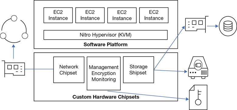
Your instances are running on a hypervisor installed on custom-designed bare-metal servers, as shown in Figure 3-3. The standard hypervisor AWS used was a customized version of XEN for a number of years, but many changes are happening. For several instance types—the C5d (massive computer-optimized instances), the M5d (massive memory-optimized instances), and the new, bare-metal EC2 instances—AWS has moved to what is called the Invocation platform with the Nitro system. Nitro is a customized version of the KVM hypervisor with a published benchmark of less than 1% when comparing virtual EC2 instance performance to bare-metal system performance. Nitro systems are also matched with a customized Nitro security chipset that monitors the firmware and hardware at boot, supports enhanced networking, and has NVMe block storage specifically designed for access to high-speed local storage over a PCI interface with transparent encryption provided on the fly by hardware processes. Scotty, I need more power! Wait a minute. I’m more than okay.
Note
If your job involves managing VMware and Hyper-V hypervisor, you have no exposure to the hypervisor at AWS. Maintaining and operating the hypervisor is Amazon’s job.
Therefore, customized bare-metal servers host multiple AWS customers and their EC2 instances, and all instances are hosted on VPCs. And there are approximately 80,000 bare-metal servers residing in a typical AWS data center. For many years when the hypervisor of choice was XEN at AWS, an emulated software router providing additional security resided just below the hypervisor. However, on the latest and greatest Nitro platform, a hardware router is directly embedded in the physical host. These routers sitting below the hypervisor provide the majority of VPC functionality and at a much greater speed.
It’s All About Packet Flow
I find that reducing the concept of the network to the packet level a simple, functional way of thinking about networking at AWS. You have packets that need to be sent from a specific EC2 instance, on a specific subnet, from a specific VPC, to a specific destination or location. At the subnet is where routing decisions are performed for the EC2 instances on each subnet. For example, instances may need access to the Internet, access to the head office, or access to data records stored somewhere on the AWS network.
How’s each packet going to get to its preferred destination? The answer is through those specialized routers/routing services hosted on each bare-metal server and some custom external hardware. Before each packet exits the subnet to its destination, AWS stamps the required proprietary data records within each packet, including the VPC encapsulation details as shown in Figure 3-4 containing essential information:
Which VPC is home base for the packet?
What subnet does the instance reside on?
What is the IP address of the instance that sent the packet?
Where is the destination service the packet needs to be sent to?
What is the IP on the physical network where your VPC is located?
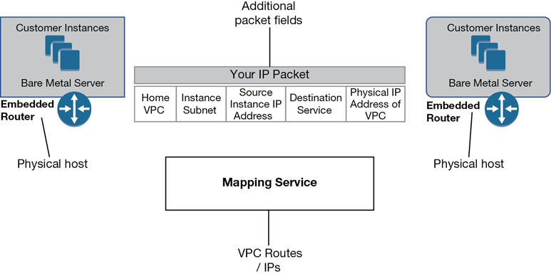
Figure 3-4 VPC encapsulation details
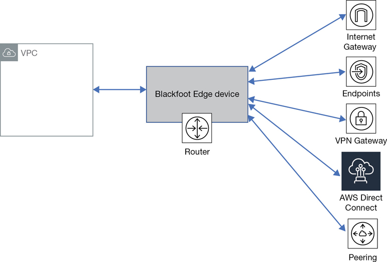
Packet flow is carried out using customized hardware components connecting to each “VPC” called a Blackfoot device, as shown in Figure 3-5. These smart devices sit on the edge of the VPC and perform a conversion for the network traffic based on the final destination each packet is headed toward. Each packet is also encapsulated with its essential personal travel information before beginning its journey. The outermost IP destination will need to identify the target physical host the packet is being sent to. In addition, each packet will have the destination VPC and destination network interface identification.
Note
Blackfoot edge devices translate the traffic residing on the internal VPC encapsulation network to the outside IP network sending each packet to its desired destination.
For example, if the traffic needs to go to the Internet, the VPC encapsulation will be stripped from the packet, and its IP addresses will be changed to a public IP address. If the destination was to an external private connection, the traffic would be directed to the requested VPN service. The Blackfoot device also adds additional protection by performing network address translation as the internal network traffic transitions to an external packet flow. With their current VPC design, AWS has successfully gone past any limitations imposed by using VLANs.
The Mapping Service
How can all the required networking information be gathered in a timely fashion? AWS uses a process called the mapping service. The mapping service is a fully distributed service in charge of mapping VPCs and their associated network interfaces and the physical locations of each VPC. Mapping decisions are highly optimized using high-speed lookup memory caches. With support for microsecond scale latencies, mappings are cached in the location where they are most used and are proactively validated when routing information is updated. According to AWS, with this design, the overall system latency is reduced to tens of microseconds. The central mapping server knows everything about every IP address, every Media Access Control (MAC) address, and where each component physically lives on the AWS network, as shown in Figure 3-6.
The mapping server replaces the traditional process of broadcasting packets to identify the MAC addresses, and multicasting to distribute information to everybody on the network. You could also think of the VPC as a tagging mechanism, where the tag of each VPC is inserted in the packet information; the packet can therefore be identified using the VPC tag as to where it needs to flow to. Both the source and the destination of each network packet are verified, and any security rules are upheld and maintained by the mapping service.
There are no broadcasts domains at AWS; the need for networkwide broadcasts has been removed. All networking information is instead held and maintained within the distributed mapping tables. On a traditional network, we would first broadcast and find out the destination information and then create the packet and send it off. Not at AWS. Broadcasts from millions of customers would bring down the network; therefore, no broadcasting is allowed outside of each subnet. Hopefully you found the last few pages an interesting summary of some of the cool networking components running inside of Amazon’s data centers. Now that we have some background, let’s look at creating our first VPC.
Creating Your First VPC
The initial creation of a VPC is either a very simple or a slightly more complex process depending on what tool you choose to use. Two wizards are available: the Launch VPC Wizard and the Create VPC. Each wizard shows up at different levels in the VPC management console, and that adds a bit of confusion because each wizard asks different questions and then carries out different tasks. You can also use the Amazon command-line interface (CLI) and enter a simple command-line string to create a VPC. Each of the choices available for creating a VPC carries out the creation task a little differently.
Example 1: Create the VPC
For our first example, we will click the Your VPCs link from the main VPC Dashboard. You must answer a couple questions when creating a VPC with the Create VPC wizard.
What is the name tag? That’s the name of the VPC being created.
What is the initial IPv4 CIDR block you want to use for the VPC?
There are two additional menu choices that allow you to add an IPv6 classless inter-domain routing (CIDR) range and make a choice about VPC tenancy. The tenancy option allows you to change from the default mode of running your future instances on shared hardware, called multitenancy, or single-tenancy hardware.
Hosting instances at AWS in a VPC on shared hardware resources means that other AWS customers will also be sharing the underlying bare-metal server hardware and hypervisor along with you. You will not know which customers you are sharing AWS resources with. Selecting dedicated tenancy forces you to run your EC2 instances within the VPC designated as dedicated on single-tenant hardware with you being the only tenant, or customer. This may be an important consideration if you’re bound by strict governance rules requiring you to operate with dedicated compute instances when operating in the AWS cloud.
Running dedicated EC2 instances at AWS is more expensive than multitenancy operation. A $2 charge per hour will be added when dedicated instances are running. Let’s return to the steps for creating a VPC with the Create VPC wizard.
Using the Management Console, click Services, and under Networking and Content Delivery, select VPC.
From the VPC Dashboard under Virtual Private Cloud, select Your VPCs.
Click the blue button Create VPC.
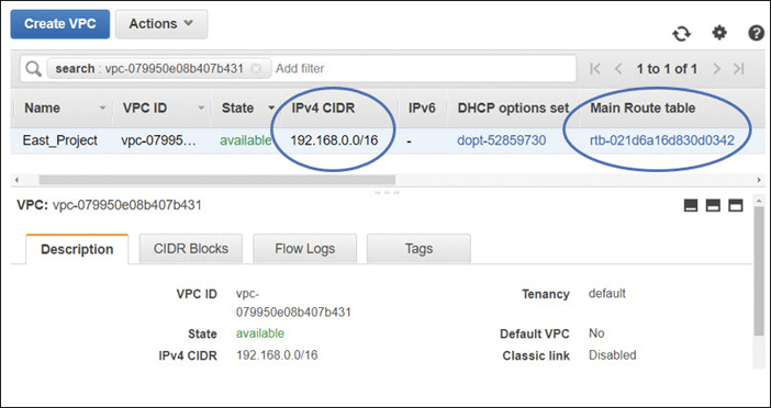
In the Name tag dialog box shown in Figure 3-7, enter the name of your VPC.
In the IP CIDR Block dialog box, enter the range of IP addresses you want to use in CIDR notation. For example, enter 192.168.0.0/16, which would allow you to create subnets within the VPC that could total approximately 65,530 possible hosts.
Optionally change the default tenancy from shared to dedicated.
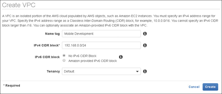
Figure 3-7 VPC questions using the Create VPC wizard
Example 2: Launch the VPC Wizard
From the main VPC Dashboard for this example, click the Launch VPC Wizard button.
This more powerful wizard option prompts you for answers to additional questions depending on the VPC design that was chosen. In addition to specifying the default CIDR block for the VPC, you also specify the CIDR blocks for the subnets that you want to create.
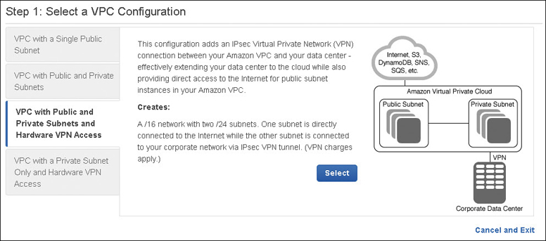
Other networking information details such as NAT servers and customer gateway configuration settings can also be added. These VPC wizards can be handy to get you started, but they are also limiting; for example, you can’t create multiple public and private subnets in multiple availability zones with the wizard. However, the Launch VPC wizard, as shown in Figure 3-8, is useful in visualizing the components required with the available VPC designs. You can use the VPC management console to add additional subnets anytime.
The following are VPC design choices we can consider:
VPC with a Single Public Subnet—This option creates a single public subnet that could be useful for a simple test environment or for a public-facing software as a service(SaaS) application. It might also be useful if you want to design with multiple VPCs for controlling incoming traffic flow through a transit network.
VPC with Public and Private Subnets—Creating a VPC with public and private subnets allows you to create an environment for a multi-tier application. The public subnets would be utilized for network address translation (NAT) servers or additional public-facing services such as load-balancing services. Multiple private subnets could be created and used for hosting, Web/application servers, and database servers.
VPC with Public and Private Subnets and Hardware VPN Access—This choice is like the second example above but also allows you to add a private VPN connection.
VPC with a Private Subnet Only and Hardware VPN Access—This choice is also like the second example, but there are no public subnets created.
After using the Launch VPC Wizard to create your initial VPC infrastructure, you can add additional subnets or connectivity that you require using the other options in the VPC console. The wizards are merely a starting point for most real-world network designs. You can also choose to use the AWS CLI tools to create a VPC, as shown in Figure 3-9.
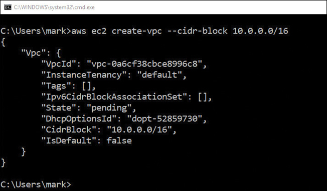
To access the companion videos, register your book at informit.com/register.
If you used one of the VPC wizards or the AWS CLI, congratulations! You have created a VPC. Depending on the wizard or the creation process used, the VPC might be completely empty with just the required IPv4 CIDR block, or you may have fleshed out your design by choosing public, or public and private subnets, and associated network connectivity infrastructure. This is probably a good time to pause and think about how many VPCs you might need. This is a long-term question for your company. You may have many developers with many accounts creating many VPCs without regard for other developers who are also creating VPCs. You might need a single VPC today, but what about tomorrow? How much expansion will you need over the next two years?
Note
Terra Firma’s human resources system requires at the very least one VPC, but just how many will they need in the future needs to be discussed? Will their network design require a separate test bed VPC for development? Perhaps an additional VPC to test for quality control, and of course, a VPC for the live application? What if Terra Firma decided to operate in multiple regions? What if multiple developers with multiple accounts worked on the development of the human resources system? You can see how complicated this decision could get.
How Many VPCs?
There are initial limits to the number of VPCs that we can create. The default “soft limit” is five VPCs per AWS account. You can request additional VPCs resources up to the defined hard limit. The current hard limit for VPCs is the current number of VPCs in the region times the number of security groups per VPC. The total figure cannot exceed 1,000. This is but one example of hard and soft limits defined by AWS for each service. Check the AWS documentation for each AWS service that you are planning to deploy to find the current hard and soft limits and plan accordingly.
Note
Hard and soft limits are per AWS account, per region. With 20 regions available at AWS, a single AWS account can create 100 VPCs, 5 per region.
Consider these possible design options for calculating the number of VPCs required:
Your company wants to extend, or burst, into the cloud utilizing resources in the corporate data center and at AWS. Your primary need is additional compute resources at certain times of the month. In this scenario, one VPC could be the solution. A single VPC can host many subnets and instances and have private connectivity back to the corporate data center.
You are an independent developer creating an application that will be available across the Internet to users around the world. You have no corporate data center. The solution is to start with one VPC. Perhaps you will soon want to have a development workspace, a test workspace, and a production workspace, and you want them all to be separate. Now you have potentially three VPCs within a single region.
You’re an administrator who has been tasked with utilizing cloud storage at AWS. You need unlimited storage, and you don’t know the upper limit of your storage requirements. Your solution doesn’t need a VPC. You need storage—perhaps S3 object storage or Glacier archiving. This is an example of the service itself not residing within a VPC. You can find more details on S3 storage in Chapter 6, “Cloud Storage.”
You work for a large company, with several developers and administrators, and many departments spread across many continents. You may have many AWS accounts and many VPCs to contend with. Don’t worry! We can work with multiple VPCs and multiple accounts with VPCs, but it’s a great idea to have some long-term plan perhaps 2 to 3 years out if possible. At the end of this chapter, we will look at some discussion points to save you some potential future pain.
You work for a large company that is hosted in many different countries with different languages. Your company wants absolute separation; multiple VPCs can be created.
Creating the VPC CIDR Block
A VPC created using either a simple AWS CLI command or the main Create VPC wizard is really a blank slate except for the primary IPv4 CIDR block and the local main routing table. Here are some CIDR details to be aware of:
Both IPv4 and IPv6 subnets are supported within a VPC; however, it is required that VPCs and subnets have an initial IPv4 CIDR block defined first.
IPv6 CIDR blocks can be associated with your VPC, but only after an initial IPv4 CIDR block has been created.
CIDR blocks must not overlap with any existing CIDR blocks associated within a VPC or with another VPC connected with a peering connection. Overlapping CIDR blocks are an issue to be avoided unless it’s a deliberate decision to ensure that a VPC cannot connect to another VPC, regardless of the situation.
The size of an existing CIDR block cannot be increased or decreased; it is locked after creation.
Planning Your Primary VPC CIDR Block
There are many questions, and many possible answers, when planning your IP addressing for your VPC. I can’t stress it enough that if you are not the prime networking expert at your company, you should talk to your networking team and get advice on what IP address ranges you should use at AWS. Two or three years down the road, you may want to connect your networking hosted at AWS to your corporate network, and you might find out that the IP address range you selected wasn’t the best choice. Meeting with your network team could save you hours of future reworking and save you from a serious meltdown. Your initial IP addressing choices could come back to haunt you without proper planning. We’ll explore these issues when we discuss joining VPCs together.
Note
The primary IPv4 CIDR block that you choose for your VPC will determine the number and size of IPv4 addresses that can be assigned to the subnets created within the VPC. The initial CIDR block that was added when you created the VPC can’t be changed; however, you have the option of adding additional secondary CIDR blocks to an existing VPC. We will expand upon using additional secondary CIDR blocks in a few pages.
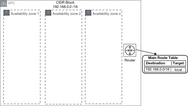
Let’s start with the example of 192.168.0.0, as shown in Figure 3-10. For your VPC starting CIDR address, the network mask you choose will determine the number of possible hosts that can be contained on subnets within your single VPC.
Note
Amazon supports netmask sizes from /16 to /28.
As discussed, during the creation of a VPC, it’s mandatory that an IPv4 CIDR block is assigned to a VPC even if you’re planning to use IPv6. However, VPCs can also operate in a dual stack mode communicating over both IPv4 and IPv6 protocols. The subnet CIDR block for IPv6 is fixed at /64. During or after VPC creation, you can choose to associate an IPv6 CIDR block to your VPC and subnets. Reviewing the sample address ranges shown in Table 3-2, you will be able to find an acceptable range of hosts and addresses to match your project. When in doubt, explore increasing the subnet CIDR block size to accommodate more hosts.
Table 3-2 VPC CIDR Block Examples
CIDR Block |
Addresses Range |
Hosts |
|---|---|---|
192.168.0.0/16 |
192.168.0.4–192.168.255.254 |
65,529 |
192.168.0.0/18 |
192.168.0.4 and 192.168.255.254 |
16,379 |
192.168.0.0/19 |
192.168.0.4 and 192.168.255.254 |
8,187 |
192.168.0.0/20 |
192.1, 68.0.4 and 192.168.255.254 |
4091 |
192.168.0.0/21 |
192.168.0.4 and 192.168.255.254 |
2043 |
192.168.0.0/22 |
192.168.0.4 and 192.168.255.254 |
1019 |
192.168.0.0/23 |
192.168.0.4 and 192.168.255.254 |
507 |
192.168.0.0/24 |
192.168.0.4 and 192.168.255.254 |
251 |
192.168.0.0/28 |
192.168.0.4 and 192.168.255.254 |
11 |
Note that the first four IP addresses 0, 1, 2, and 3) and the last IP address (255) in each subnet’s CIDR block are reserved for Amazon’s use. Using /22 as a standard netmask for all subnets, the maximum number of hosts is 1019, which for a lot of use cases would be fine. However, if you’re creating a subnet for hosting thousands of clients utilizing a VDI solution, make sure to pick a larger range for future expansion. On a private subnet for databases, you could go as small as /28. You will not have 11 database hosts on a single subnet.
Adding a Secondary CIDR Block
Up to four secondary IPv4 CIDR blocks can also be associated with an existing VPC. After adding an additional CIDR block, the new route is automatically added to the VPC main route tables, enabling the additional local routing routes throughout the VPC. Keep in mind that the additional secondary CIDR block cannot be larger than the initial primary CIDR block. For example, if you associate a primary CIDR block of 10.0.0.0/24, an additional CIDR block of the same range or larger is not allowed. However, a CIDR block of 10.0.0.0/25 is allowed because it’s a smaller range.
The primary advantage of being able to add additional secondary CIDR blocks to an existing VPC is having the ability to add future expansion when necessary. If the initial primary CIDR block caused address space limitations, additional secondary CIDR blocks can be added allowing you to increase the number of IP addresses that can be used within the VPC.
The Default VPC
You may have come across the default VPC if you have been playing around with AWS and adding an initial instance. The default VPC is available within each AWS region and is created with an IPv4 CIDR block of 172.30.0.0/16, which provides up to 65,531 private IP v4 addresses. In addition, an Internet gateway has been created and attached to the default VPC with a route table entry that sends all IP traffic intended for the Internet to the attached Internet gateway. A default security group and default network ACL are also associated with the default VPC. For each default VPC, subnets have been created for each AZ in the region where it’s located. All that’s left for you to do is to add instances. Instances placed on the default public subnet within the default VPC receive both a public and a private IPv4 address and public and private DNS host names. Potentially, your Web application is ready to go. Well, hold on just a second.
The idea behind AWS already providing a prebuilt default networking VPC environment is to enable you to start working quickly with AWS, even if you have limited network knowledge. The default VPC can be handy if you want to do a quick demo and don’t want to bother setting up subnets and Internet connectivity and think about any CIDR decisions. These networking decisions have been already carried out for the default VPC.
Note
The default VPC’s infrastructure is set up for public Internet access. However, the customer still makes the final decision for allowing public Internet access to a VPC by associating a public IP address with an EC2 instance during its creation. Allowing public access to AWS resources is always the customer’s choice.
Perhaps having a separate demo AWS account utilizing the default VPC would be useful for demonstrations and more. However, the default VPC can easily cause deployment issues when you are selecting a service that requires network placement. If you’re not paying attention, the default VPC will be preselected, as shown in Figure 3-11. And you may not want Internet access, which has been defined for the public subnets of the default VPC. For these reasons, for most deployment options other than a demo account, I would recommend deleting the default VPC from every AWS region in your AWS account. Yes, this means you would have to set up all your networking from scratch. But perhaps long term you’ll be happier knowing there’s no default VPC with easy Internet access provided to the unsuspecting user. It’s a really good idea to understand and control all your networking options when operating in the cloud.
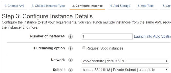
Note
The default VPC can be deleted. If you want to bring it back, AWS provides a script to re-create it. You also can’t assign an existing VPC to become a default VPC.
Revisiting Availability Zones
Availability zones were discussed previously in Chapter 2, “Designing with AWS Global Services.” If you are comfortable with the concept of availability zones, you can skip this section. As you may remember, within each VPC, the number of availability zones that are available depend on the region the VPC is created in.
Creating a VPC in the N. Virginia region will give you the option of selecting up to six AZs that can be used within a single VPC to design a resilient network. Choosing the Canadian region, you would have just two AZs to work with. The stated long-term goal is that new AWS regions will have three or more zones. Subnets are created in each AZ. Next, instances are placed on the appropriate subnets. Utilizing AZs allows you to do the following:
Design for resiliency and failover with multiple AZs in a single VPC.
Load-balance instances hosted on subnets in different AZs. (See Chapter 5, “Planning for Scale and Resiliency.”)
Auto Scale instances hosted on subnets in different AZs. (See Chapter 5.)
Deploy RDS primary and slave database servers hosted on subnets in different AZs. (See Chapter 6.)
Creating Subnets
After an initial VPC creation, your next step is to create subnets within the VPC, per AZ(s), depending on your required network design. The AZs that you select for each subnet are already hosted and available within the VPC. It’s usually stated that a VPC spans “all of the availability zones within its region” and certainly, there is the potential to include all the AZs within a VPC if your design includes subnets for each AZ. However, AZs don’t show up automatically in each VPC; they are added during subnet creation when selecting each subnet’s location.
Each subnet that you create resides within its assigned AZ, and although AWS doesn’t share the physical details, each subnet is hosted in exactly one data center within the selected AZ, as shown in Figure 3-12. If you choose to design your applications for resiliency and uptime, you’ll want to design your solution using at least two AZs. As we know, AZs have been designed with isolation from other AZs; a failure in one availability zone will not affect the other AZs within the VPC and region.

AWS also carries out a balancing of sorts of customers across the listed AZs within a region. If I create a subnet in the N. Virginia region and select availability zone-a, and you also create a subnet in the N. Virginia region, selecting availability zone-a, the odds are high that my subnets are not in the same physical AZ as your subnets. We each have subnets in a selected AZ in N. Virginia. That’s as much location detail as were going to get in the AWS cloud.
Every subnet that you create begins life as a private subnet with no connectivity. You may be intent on creating a subnet with Internet access, but you have a few tasks to carry out: you must first add, and then attach, an Internet gateway to the VPC and then manually update the route table associated with the public subnet with a route table entry, pointing to the Internet gateway. Only after every one of these steps is taken will you have an official public subnet.
Note
Subnets are defined by their connectivity options.
If subnet traffic is routed to the Internet through an Internet gateway, the subnet is defined as a public subnet.
If a subnet has no gateway or endpoint to direct traffic to, it is a private subnet. Traffic remains on the local subnet and has nowhere else to go. A subnet with no external gateway connectivity is the true definition of a private subnet.
Amazon documentation sometimes defines subnets that are routed to a virtual private gateway as a VPN-only subnet distinguishing that there is another network to connect to—a private gateway location. Therefore, it is not as private as a subnet with no gateway connections. Terra Firma and its human resource application will need the following subnet types:
Public subnets for load balancers and NAT services
Private subnets for the database servers
Private subnets for the Web servers
Subnet Summary
Subnets are contained within an AZ.
Subnets host compute instances.
Public subnets allow you access to the Internet.
Public subnets are for infrastructure.
Private subnets are private with no Internet access.
Private subnets are where instances live privately.
VPN-only subnets have access to a VPN connection, typically to and from the head office.
NAT Services
At AWS, a NAT gateway service can be ordered and linked to a public subnet to allow EC2 instances in a private subnet to connect to the Internet and receive required operating system and application updates. The NAT gateway service is always placed in a public subnet and configured with an elastic IP address that’s a static public IP address, as shown in Figure 3-13. On each created NAT gateway, a network interface is added that is assigned a private IP address from the IP address range of your subnet. The elastic IP address is for public communications, and the private IP address is for the private communications with the private subnets. For additional redundancy, create NAT gateways in each AZ and ensure the route tables, entries in each private subnet point the EC2 instances to the correct gateway location.
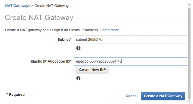
Note
The NAT gateway service initially supports up to 5 Gbps of bandwidth throughput and can scale up to 45 Gbps as required.
A NAT EC2 instance could also be built and hosted in a public subnet to allow instances in a private subnet to connect to the Internet through the NAT connection and receive required updates as necessary. However, you must completely configure and manage each NAT instance. If you decide this is the method that you want to utilize to provide NAT services, Amazon recommends that you build your NAT instance using the latest version of the NAT AMI. A NAT security group must also be created and assigned to the NAT instance, and, quite possibly, you will have to create an HA pair of NAT instances for redundancy. When building NAT instances, one configuration change needs to be enabled during installation: source destination checks must be disabled because the NAT EC2 instance is not the final source and destination for the traffic it sends and receives. The only reason I can think of why you would want to build your own instances for NAT services is if your environment needs to support port forwarding. The NAT gateway service that AWS supplies does not support port forwarding.
NAT Gateway Summary
NAT services are used so EC2 instances residing on private subnets can get required updates.
The NAT gateway service is a hosted AWS cloud service with no need to install or maintain an EC2 instance.
A NAT EC2 instance is merely an instance configured for NAT duties.
Working with Route Tables
A subnet route table is a defined collection of rules that dictate where egress subnet network traffic can flow to. As previously mentioned in the subnet discussion in this chapter, each subnet must be associated with a route table; and each VPC has local routing functionality built in implicitly. Multiple subnets can also be associated and controlled with a single route table, and a single route table can be assigned to multiple subnets. You may have multiple private subnets that need routes to the same service, such as a NAT gateway service to get required updates, or to a virtual private gateway for connections to the head office. Here are some common route table considerations:
Each VPC has a main route table that provides local routing throughout the VPC.
The main route table can be modified, but don’t do this. Instead, leave the main route table with just the local routing routes defined within the VPC. Any custom routes required by a subnet should be allowed with a custom route table. Leaving the main route table in its default state ensures that if you assign the main route table by mistake to a subnet, the worst that can happen is local routing.
The main route table cannot be deleted. However, it can be ignored and remain unassigned if you do not associate it with any subnets within the VPC.
Each route table entry defines a destination that is defined by CIDR notation and an external target. For example, a common destination is the corporate network, which can be reached through the virtual private gateway.
Subnet traffic is matched with the most definitive defined route within the route table that matches the traffic request.
Existing route tables are not automatically populated with routing rules to any network services that you order within your account. When routing services such as an Internet gateway (for IPv4 public Internet traffic), or Egress only Internet gateway (for IPv6 traffic) are attached to a nondefault VPC, they are not automatically added to a route table. They must be added manually. The exception to this rule is the default VPC, or VPCs created with the Launch VPC Wizard.
Note
After the initial association of the main route table to a newly created VPC, AWS makes no additional routing decisions.
The Main Route Table
As mentioned, the main route table provides local routing services throughout the VPC across all defined AZs, as shown in Figure 3-14. Each route table, whether custom or default, has an entry containing the VPC’s initial CIDR designations, and this entry cannot be changed. The main route table also defines the routing for all subnets that are not explicitly associated with any other custom route table after they are created. Only after a subnet is created can the associated route table be changed from the main route table to the desired route table.
Note
Every subnet, when it’s created, is automatically assigned to the main route table of a VPC. This is a protective step as the assumption is made that the main route table will only provide local routing throughout the VPC.
Custom Route Tables
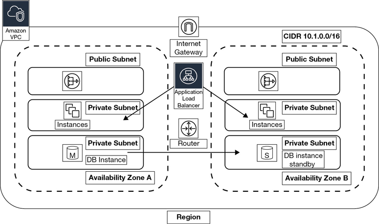
It is considered a best practice to create custom route tables for each tier in your network design. Creation of custom route tables allows you granular control of traffic flow within each subnet. Let’s look at an example: Terra Firma is thinking of starting with a two-tier design for its human resource CRM application. It has decided to use two AZs within the VPC to provide for additional availability and failover for the application and database servers.
Public and private subnets will be created within each AZ, with public subnets for hosting the NAT gateway service, which allows instances on the private subnets to get updates as required, and a public-facing load balancer for balancing the user requests across the availability zones. Separate private subnets will also be created for the EC2 instances hosting the application servers, as well as the MySQL database instances, as shown in Figure 3-15. The database servers will utilize synchronous replication from the primary to the secondary server, ensuring the database records remain up to date.
Note
This example is merely a starting design. The actual number of VPCs to be created is still under discussion by Terra Firma. Perhaps the first VPC should be considered for initial design and testing purposes, with other VPCs created for production and quality control. The server and database migration tools provided by AWS also need to be tested and approved.
For our initial design, after the subnets have been created, custom route tables need to be created for the following subnet groupings, as shown in Figure 3-16:
Public subnet infrastructure—ELB, NAT gateway service. A custom route table will be created for the public subnets by adding a route for the Internet gateway enabling public network traffic between network interfaces hosted on the public subnets assigned with public IP addresses and the attached Internet gateway. (Of course, the first task is ordering an Internet gateway; next you must associate the Internet gateway with the VPC.) Internet gateway routes are usually set with a destination route of 0.0.0.0/0 because the destination may be anywhere on the public Internet. For our initial design, perhaps the destination route could be a smaller range of Terra Firma’s public IP addresses.
Application and database tiers—The application servers will be hosted on private subnets within each AZ. The master and slave database instances will be either a custom implementation or managed by the relational database service (RDS). To enable EC2 instances hosted on a private subnet to protectively connect to the Internet and receive required updates, the NAT gateway service will be hosted on public subnets within each AZ. Routes pointing to the NAT gateway service must be defined in the route table associated with the private subnets.
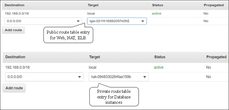
Figure 3-16 Terra Firma’s custom route tables
Route Table Summary
Configure the main route table for local routing.
Configure custom routes for public subnets.
Configure custom routes for private subnets.
We now need to talk about TCP/IP address types. IP addresses that are assigned to EC2 instances depend on the subnet types that are selected during the creation of the instance. Let’s look at the IP address options available at AWS, starting with private IPv4 addresses.
Private IPV4 Addresses
When a client launches a new EC2 instance, by default, Amazon assigns a private IP address to the primary virtual network interface card from the range of available IP subnet addresses. (Of course, there could be more network interfaces as well, and they would also have addresses assigned.) Private IP addresses communicate across the private network at AWS. A private DNS host name that points to the associated private IPv4 address is also assigned to each instance. If you choose to manually assign a primary private IP address, the IP address chosen must be available in the subnet’s IP address range where the EC2 instance will reside. You can assign any IP address in the assigned subnet range if it is not in use or reserved by AWS.
Note
Once a primary private IP address is assigned, the EC2 instance retains the address for the lifetime of the instance.
Additional, secondary private IP addresses can also be assigned to the network interfaces of an EC2 instance, and these addresses can be unassigned and moved between other EC2 instances that reside on the same subnet at any time. Any network interface other than the primary network interface (eth0) can also be detached and moved to other EC2 instances hosted within the same AZ and within the same VPC.
Note
Let’s again discuss the concept of cost at AWS. Communication between EC2 instances residing on the same subnet using their private IP addresses is free of charge. However, EC2 instances using private IP addresses located on subnets in different AZs are charged an outbound data transfer fee for communicating with each other.
The Simple Monthly Calculator is useful to carry out detailed pricing scenarios. http://calculator.s3.amazonaws.com/index.html
Private IP Summary
EC2 instances don’t need public IP addresses; they need private IP addresses.
Private IP addresses are cheaper cost-wise than public IP addresses when sending network traffic.
Public IPv4 Addresses
Another addressing option available at AWS is a public IP address that is typically assigned from AWS’s pool of public IP addresses, as shown in Figure 3-17. Public IP addresses from AWS’s own pool are managed and controlled by AWS and are therefore not permanently assigned to an EC2 instance. Whether or not your EC2 instance receives a public IP address during creation is dependent on how the public IP addressing attribute has been defined on the subnet where the EC2 instance is to be hosted. At the subnet attribute level of any subnet you have created, the IPv4 public addressing attribute is initially set to false, meaning no public IPv4 address will be assigned to any EC2 instances at creation. This is another example of the customer being in control of what exactly is made public at AWS.

Enabling the public IP addressing attribute can also be carried out during the creation of an EC2 instance resulting in an AWS-controlled public IP address being assigned. This can overrule the default state of the subnet’s public IP address attribute. If you create a subnet and don’t change the subnet defaults, public IP addresses are only assigned to EC2 instances that enable the public IP addressing attribute during installation.
Let’s explore the launch of an EC2 instance that is assigned an AWS-controlled public IP address.
You create an EC2 instance and enable the option to assign a public IP address to the instance during launch, overruling the subnet defaults.
After successfully creating your EC2 instance, you open a PuTTy session and connect to the instance successfully. Everything seems terrific.
You turn off your EC2 instance. Then you turn your instance back on and attempt to connect once again using PuTTy.
This time, your attempt to connect fails. You check your credentials and your key pair. Everything seems okay on your end.
Then you check your assigned public IP address. It has changed!
Here’s what’s happening in the background. Remember, the assigned public IP address is from Amazon’s controlled pool of public IP addresses. There’s a finite number of these addresses available. To make sure that AWS doesn’t run out of addresses, the AWS-assigned public IP address is detached when an EC2 instance is turned off. Once the instance is turned back on, AWS assigns a new public IP address. You may be thinking; “I don’t want my public IP address to change when I turn my instances off and on.” The good news: there is a solution with the assigning of what is called an elastic IP address.
Note
The reality is that if you have a Web/application server hosted at Amazon in a VPC, you don’t need a public IP address. The private address is a much better solution. How do customers connect to a Web server hosted in a private subnet? Easy. Place a public-facing load balancer hosted on the public subnet in your VPC, and direct the incoming traffic to the private subnet where your Web/app servers are located.
Elastic IP Addresses
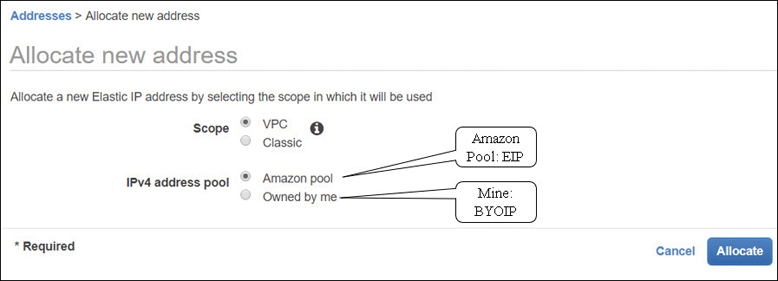
A public elastic IP address (EIP) is a static public IP address that after creation is assigned to your account at AWS. There are two types of EIPs: a public version and a private one. First let’s discuss the public version; later in the chapter we will discuss a technology called PrivateLink, which uses the private EIPs. Requesting an elastic IP address is simple. You simply request an elastic IP address, as shown in Figure 3-18, and voilà, it’s added to your account from the regional pool of available EIPs. It arrives unassigned; your job is to next assign the EIP to the desired VPC in the region and finally assign the EIP to the EC2 instance.
AWS advertises each regional pool of elastic IP addresses across the public Internet and to all other AWS regions. Because of this advertising, EIPs hosted at AWS can be located across the public Internet and within the public AWS address space.
Note
There is a public listing of all available AWS EIP addresses that can be found: https://docs.aws.amazon.com/general/latest/gr/aws-ip-ranges.html.
Turning an EC2 instance that has a public IP address, an EIP, off and back on is no longer an issue; the EIP remains attached because it’s assigned to your AWS account and to the EC2 instance. And there’s no additional charge if you order and assign an EIP to an instance. However, if you don’t assign an EIP address after you have received it, AWS charges you an additional fee as EIP addresses are in limited supply. Therefore, at AWS, there are two public pools of IP addresses to consider: Dynamically assigned public IP addresses that are returned to the common public pool of AWS addresses, or elastic IP addresses, which are assigned as desired after ordering and assigned to a customer’s account. Let’s work through another common scenario:
You spin up an instance and forget to assign a public IP address to the instance during the creation.
Your attempts to connect to the instance using PuTTy are not successful.
You can’t connect because there is no public IP address; you’re trying to connect to the private IP address assigned. Aha!
After requesting and receiving an EIP address, you associate it with your instance.
You successfully connect to the public elastic IP address using PuTTy.
The public IPv4 address will be displayed as an attribute of the network interface when viewed through the management console, but the internal wiring is a little more complicated. On an EC2 instance with a public IP address, this address is internally mapped to the instance’s primary private IPv4 address using NAT services. When a public IP address is assigned to an EC2 instance, the outbound traffic is sent to your instance’s private internal IP address.
Assuming your EC2 instance is directly addressable from the Internet when someone wants to directly reach your instance, the inbound destination is the public IP address. When the instance needs to communicate outbound across the Internet, the source address is its public IP address. Queries on the private network of the EC2 instance always use the private address of the instance. The takeaway from this example is that AWS attempts to use the private IP address, whenever possible, for network communication with an EC2 instance.
Each EC2 instance that receives a public IP address at AWS is also provided with an external DNS hostname. As a result, the external DNS hostname is resolved to the public IP address of the EC2 instance when queries are external to AWS.
Public IP Summary
Use EIPs for NAT instances.
EIPs are also used for both public-facing and private load balancers.
EIPS are used for the NAT gateway services
Public IP addresses are not necessary for EC2 instances
Traffic Charges
It’s important to realize that public traffic and private traffic are charged differently at AWS. Costs at AWS can become extremely expensive if you don’t pay attention. This is but one example to consider: public traffic sent to a public IP address traveling across the Internet will have a much higher data transfer charge than private IP address traffic. Private traffic traveling within AWS data centers is always cheaper than traffic on a public subnet, as shown in Figure 3-19. Therefore, whenever possible, AWS uses the private network for communication.

Private traffic that stays within a single subnet has no additional charges, whereas private traffic that travels across multiple private subnets that are hosted by different AZs has an egress charge of $.01 per GB. This might sound perfectly fair and inexpensive, but think about database replication from the master database instance to the secondary database instance, with each instance located in a different AZ. If the database is a production database, expect a significant charge for the synchronous replication of your data from the primary to the secondary database instance. This is but one of many methods of how AWS charges you for using hosted cloud resources. One of the jobs Terra Firma must carry out is a detailed costing of its initial design, including the replication of the databases across AZs, the cost of the load balancer, the monthly charge, plus the traffic flow.
Note
All inbound communication traffic that an EC2 instance receives is free, regardless of whether it comes from inside AWS or from the public Internet. However, database replication traffic across multiple AZs is charged a data transfer fee.
Bring Your Own IP (BYOIP)
If you have a public IP address range that has been approved for use by your compliance rules, or a specific public IP address has been white-listed as a reputable IP address for a well-known hosted public service, you may want to use these public IP addresses at AWS. The good news is that it’s now possible to have control over your own public IP addresses at AWS. BYOIP allows customers to move their existing public IPv4 address space to AWS, as shown in Figure 3-20. Each customer still owns her public IP range; however, Amazon hosts and advertises the public IP address range across the Internet and AWS regions for you. Bringing your own public IPv4 address space to AWS allows you to accomplish the following tasks:
Maintain your public IP address reputation.
Avoid any changes to public IP addresses that have been white-listed.
Avoid changing IP addresses utilizing legacy applications.
Use a public IP address as a hot standby failover for on-premise resources.
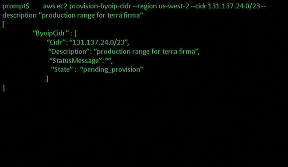
Figure 3-20 BYOIP address architecture at AWS
Reasons for wanting control of your own public address space in the cloud could include the following situations:
What if you want to keep a recognizable public IP address but have the service assigned to that address hosted on AWS?
What if you had 10,000 hard-coded lottery machines and you wanted to change the hardware devices to virtual ones at AWS with your public IP addresses?
What if you had 2,000 hard-coded public IP addresses within your data center and you wanted to change the physical location of your data center to AWS but keep the same public IP addresses?
What if you had legacy workloads—or older applications relying on specific fixed public IP addresses? These IP addresses can now be moved to AWS.
Note
The specific prefix supported by BYOIP at AWS is /24.
The BYOIP Process
Import the public IP address, or the range of public IP addresses, into AWS. AWS creates a pool of these addresses and assigns the address pool to you.
Advertise the public address range.
Allocate EIP addresses from your AWS hosted pool of public IP addresses.
Step One: Provision Your Public IP Addresses
aws ec2 provision-byoip-cidr --region -cidr <cidr range>
After AWS has analyzed and accepted the range of public IP addresses, the state of the public address range to be hosted at AWS changes to “provisioned” indicating that the IP address request has been accepted. At this point you will be able to use these public IP addresses, but they have not yet been advertised across the Internet or to the peering partners of AWS.
Step Two: Advertise the Newly Created IP Address Pool Using the Advertise Command
aws ec2 advertise-byoip-cidr -- region <cidr range>
After this command has executed, the state of the address space changes from provisioned to advertised, as shown in Figure 3-21. The address range is now advertised across the Internet and to all the peering partners of AWS. Once the advertising process has been accepted and started at AWS, it’s time to stop the advertising of the same public IP addresses to avoid any funky duplication routing conflicts.

Step Three: Allocate an EIP from Your Range of IP Addresses
aws ec2 deprovisioning-byoip-cidr--range address range
When using the hosted pool of addresses at AWS to allocate elastic IP addresses, you can select a random IP address from the hosted pool or select a specific IP address.
If, in the future, you decide you don’t want AWS to advertise and host your pool of public IP addresses, you can execute a “withdraw” command to change the state of the public IP addresses from advertised back to an unadvertised state. At this point, AWS no longer advertises your public IP addresses. The last step is to run the deprovisioning command to remove the assigned elastic IP addresses.
IPv6 Addresses
Remember that even though IPv6 addresses are fully supported within a VPC, an IPv4 CIDR block must be created first. The allowable format for IPv6 addresses is 128 bits, with a fixed CIDR block size of /56. Amazon is in control of IPv6 addressing; you cannot select your own CIDR range. Note with IPv6 addresses at AWS that there is no distinction between a public and a private IPv6 address.
Note
At AWS, IPv6 addresses are public addresses. Amazon also does not provide support for a DNS hostname for assigned IPv6 addresses.
If your instance is configured to receive an IPv6 address at launch, the address will be associated with the primary network interface. As noted earlier, instances at AWS do not have IPv6 DNS hostname support. Assigned IPv6 addresses are also persistent; you can stop and start your instance, and the IPv6 addresses remain assigned. IPv6 addresses are defined as globally unique because they have a globally unique identifier. Access to the Internet using an IPv6 address is controlled by the subnet route table, or by using security groups or network ACLs.
If you are planning to utilize IPv6 addressing at AWS for Internet access, here is a short summary of the steps to follow:
Associate the AWS-provided IPv6 CIDR block with your VPC.
Create an Egress only that’s outbound only, Internet gateway (EOIG).
This allows your private subnet to enable outbound communications to the Internet using IPv6; the egress-only Internet gateway prevents inbound communications.
Update your route tables to route your IPv6 traffic to the EOIG.
For instances hosted on IPv6 public subnets, add a route that directs all IPv6 traffic from the subnet to the Internet gateway. Note that that’s the regular Internet gateway, and not the EOIG; the EOIG is controlling private outbound traffic from the private subnet.
For instances on IPv6 private subnets, create a route that directs all Internet-bound IPv6 traffic to the EOIG.
Review and update your security group rule, including rules for IPv6 addresses.
Security Groups
Security groups operate at the EC2 instance level. They protect your server’s incoming network connections by placing a software firewall around each attached network interface. Each EC2 instance will have a primary network interface (defined as eth0); you may also have EC2 instances with multiple network interfaces, and each interface will be protected with a security group.
Each security group is a collection of inbound and outbound rules that designate the port and protocols allowed into and out of each network interface, as shown in Figure 3-22.
It may not be obvious, but each network interface is attached to a single EC2 instance, and each security group is assigned to a specific VPC. Here are some details of what we can do with security groups:
Security groups are associated with a particular VPC.
Each network interface assigned to an instance hosted within a VPC can be associated with up to five security groups.
We can allow rules; we cannot specify explicit deny rules with security groups. However, if access is not specifically allowed, you are implicitly denied.
When you create a new security group, if you don’t review and change your outbound rules, all outbound traffic is allowed.
Outbound rules can be changed to a more specific outbound destination.
Security group rules are defined as stateful. Inbound traffic flowing through a security group is therefore tracked to know the state of the traffic; if the traffic is allowed in, the response to the inbound traffic is always allowed outbound. This definition can be flipped; traffic that flows outbound will have its responses allowed back in. Once security groups have been assigned, changes can be made to the security groups assigned to a network interface while the instance is operational. Security group changes will take effect usually within a few seconds.
Security groups show up in several locations in the management console; they appear in both the EC2 and the VPC console. If you were using EC2-Classic networking, the security groups you would have created would have shown up only in the EC2 console.
Think of each security group as a reusable security template stored in your AWS account. Once a security group has been created, it can be assigned multiple times within the VPC where it was created, protecting one or many EC2 instances. Up to five security groups can be applied to a single network adapter, providing an effective set of allow rules mandating what ports and protocols are allowed for both inbound and outbound traffic.
The main characteristics of security group rules are as follows:
Security groups define allow rules. (You can’t create rules that explicitly deny access.)
Security group rules allow you to direct traffic outbound from one security group and inbound to another security group within the same VPC.
Security groups don’t deny traffic explicitly; instead, they deny traffic implicitly by only stating what is allowed.
Security groups are defined as stateless; if requests are allowed in, response traffic is allowed out regardless of defined outbound rules.
For each rule, you define the protocol, the port, or port range, and the source inbound rules or destination outbound rules for the traffic.
The protocols allowed are TCP, UDP, or ICMP.
Port Range: for either TCP or UDP, or a custom protocol, this is the range of ports to allow. You can specify a single port such as port 22, or a range of ports if you’re dealing with outbound dynamic port mapping. The ports that can be assigned are defined by RFC 5237 and 7045, which define the standard TCP/IP protocols.
One important concept to grasp about security groups is that they don’t deny traffic flow. Instead, they allow traffic flow. Another equally important concept is the “direction of traffic flow” allowed by a security group. As we know, the network traffic that is allowed in by a security group rule is also allowed out. However, a defined inbound port request does not use the same port number for the outbound response. For example, if there’s a rule defined allowing inbound HTTP traffic across port 80 inbound, the outbound traffic response is allowed out, but the response traffic does not use port 80 outbound. In most cases, outbound traffic uses a dynamically assigned port called an ephemeral port, determined by the operating system of the server making the response. We will explore ephemeral ports when we cover network ACLs later in this chapter.
When a VPC is created, a default security group is also created, as shown in Figure 3-23. Note that all outbound traffic is allowed between the EC2 instances that are assigned the security group; however, any other traffic is implicitly denied. Therefore no one can get into any of the EC2 instances from the outside world because the security group did not allow any external inbound traffic. It’s also important to understand that you can’t delete a default security group; you also don’t have to use the default security groups; you can ignore them and create and assign custom security groups.
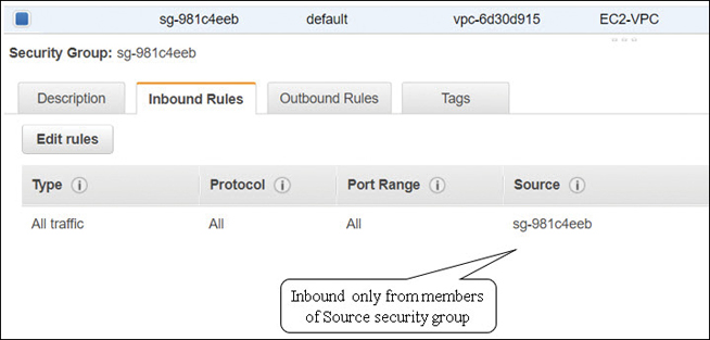
If you don’t pay attention and don’t specify a custom security group when an EC2 instance is created, at launch, the default security group is associated automatically. As we now know, the default security group allows all outbound traffic from the instance associated with the default security group, but accessing the EC2 instance from an external location will not allowed.
Custom Security Groups
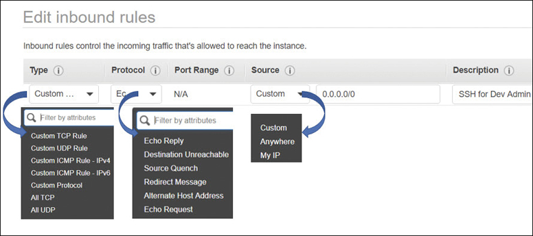
What happens when you create a custom security group? First, you must associate the security group with a specific VPC. After it is first created, a custom security group allows no inbound traffic but allows all outbound traffic by default. After the initial creation of the custom security group and selecting the security group properties, from the Inbound Rules tab you create the inbound rules defining the network traffic that’s allowed inbound. On the Outbound Rules tab, define the network traffic or security group that is allowed to communicate outbound.
Inbound rules—Define the source of the traffic—that is, where it is coming from, and what the destination port or port range is. The actual source of the traffic could be a single IP address (IPv4 or IPv6), a range of addresses, or another security group.
Outbound rules—Define the destination of the traffic—that is, where it is going to, and the destination port, or port range. The actual destination of the traffic could be a single IP address (IPv4 or IPv6), a range of addresses, or another security group.
A prefix list ID for a specific AWS network service, such as an Internet gateway
Another security group—This feature allows instances that are associated with one security group to access instances associated with another security group. The security group can reside in the same VPC or can be from a VPC that has been peered together through a VPC peering connection.
Note
Security groups “allow” access; however, security groups are also said to “deny by default.” If an incoming port is not allowed, technically access is denied.
The best practice when designing security groups is to restrict what ports need to be opened. If you place a load balancer in front of your EC2 instances, the only ports that need to be allowed by the security group protecting the load balancer are the port or ports your application requires.
For your production applications in your design, it’s a good idea to consider picking unique ports based on your production server’s tier placement. For example, in a three-tier design, Web servers could be assigned 3020 and application servers 3030, and database instances could have custom ports chosen. That’s just an extra level of security to consider. In addition, be prepared to plan for a clean security audit, or for successful troubleshooting by designing and documenting your security group’s naming scheme up front. Putting some real thought into all naming conventions pays off when you are under pressure. We have all been in this situation; fill in the blank “what’s the blasted name of the --------. Who named it that?” Here are some examples to consider for your security group configurations and initial setup.
App Server Inbound Ports
This security group has rules to allow inbound access of HTTP and HTTPS from any IPv4 address as the traffic is arriving inbound from the public Internet. As shown in Table 3-3, the source IP address of 0.0.0.0/0 indicates the traffic is allowed from any Internet location.
Table 3-3 Security Group Allowing HTTP Access
Inbound Rules |
||||
|---|---|---|---|---|
Protocol |
Number |
Port |
Source IP |
Comment |
TCP |
6 |
80 (HTTP) |
0.0.0.0/0 |
Inbound from anywhere (IPv4) |
Outbound Rules |
||||
Protocol |
Number |
Port |
Destination IP |
Comment |
ALL |
6 |
80 (HTTP) |
0.0.0.0/0 |
Outbound IPv4 traffic |
Database Server Inbound Ports
At AWS, there are a number of managed database server options available with RDS; during configuration, you can choose to use the default port address assigned based on the database product’s default port access. You could change this to a custom port number to add an additional element of security. The source IP address could be specified as a single IP address or a range of IP addresses from your subnet of application servers that need to query the database. Default RDS security group database port options are listed in Table 3-4.
Table 3-4 Default Database Inbound Ports
Protocol |
Number |
Port |
Source IP |
Product |
Comment |
|---|---|---|---|---|---|
TCP |
6 |
1433 |
Single IP address, or, A range of IP addresses |
Microsoft SQL |
Default port to access selected database instance |
TCP |
6 |
3306 |
Aurora / MySQL |
||
TCP |
6 |
5432 |
PostgreSQL |
||
TCP |
6 |
1521 |
Oracle |
||
TCP |
6 |
5439 |
Redshift |
Administration Access
If you need to connect to an EC2 instance to perform direct administration, you must associate a security group with the network interface card that has inbound rules allowing Secure Shell (SSH) or Remote Desktop Protocol (RDP) access depending on the host operating system of the instance (see Table 3-5). A database instance may be hosted on a private subnet and not directly accessible from the Internet. However, setting up a bastion host would allow access for administrators to first authenticate to the bastion host and then “jump” to the associated EC2 instance in the private subnet.
Table 3-5 Security Groups Allowing Administrative Access
Protocol |
Number |
Port |
Operating system |
Comment |
|---|---|---|---|---|
TCP |
6 |
22 |
Linux |
Public IPv4 address, or IPv6 address or range of addresses |
TCP |
6 |
3389 |
Windows |
Pinging an EC2 Instance
Pinging an instance requires access to ICMP traffic. It’s almost an automatic process; drop to a command prompt and ping the public IP address of the newly created EC2 instance. In this case, the instance didn’t get the ping request because the security group is not allowing ICMP. The ping traffic request is inbound, so you must add an inbound ICMP rule, as shown in Table 3-6.
Table 3-6 Allowing PING Access
Protocol |
Number |
Port |
Source IP |
Comment |
|---|---|---|---|---|
ICMP |
1 |
8 (ECHO) |
Admin workstation network |
Public IPv4 address or range of addresses |
Elastic Load Balancing (ELB)
Using the ELB service to “protect” your Web tier with a public facing load balancer also requires a security group with rules that allow communication with the targeted groups of EC2 instances or containers, as detailed in Table 3-7.
Table 3-7 Controlling ELB Traffic Flow
Inbound ELB Rule |
||||
|---|---|---|---|---|
Protocol |
Number |
Port |
Source IP |
Comment |
TCP |
6 |
Defined listener port |
0.0.0.0/0 for Internet-facing load balancer IPv4 CIDR block if Internal load balancer |
Inbound from anywhere (IPv4) |
Outbound ELB Rule |
||||
Protocol |
Number |
Port |
Source IP |
Comment |
TCP |
6 |
Instance listener port |
ID of the instance security group |
Outbound traffic to instance’s listener port |
TCP |
6 |
Health check port |
ID of the instance security group |
Outbound traffic to instance health check port |
Load balancers also can perform health checks on the EC2 instances that are registered with the load balancer. Health check communication from the load balancer on both the listener and the health check ports must be defined, as shown in Table 3-8.
Table 3-8 ELB Communication
Inbound Instance Rule |
||||
|---|---|---|---|---|
Protocol |
Number |
Port |
Source IP |
Comment |
TCP |
6 |
Instance listener port |
ID of the load balancer security group |
Traffic allowed from the load balancer traffic to the instance’s listener port |
TCP |
6 |
Health check port |
ID of the load balancer security group |
Traffic allowed from the load balancer to the instance health check port |
Note
Security group entries for IPv4 and IPv6 are added as separate rules.
The initial limit for the number of security groups that can be applied to a network interface is 5; you can request an increase from AWS support increasing the limit up to 16. How many rules are allowed per security group? Again, soft limits decree that every custom security group can have up to 50 inbound, and 50 outbound, IPv4 or IPv6 rules. You can increase the number of rules per security group by contacting AWS.
AWS is right to have these limits; imagine a situation in which there were no limits on the number of security groups and rules. Is it possible to slow down an instance by having too many rules to calculate and determine what is allowed? I think we know the answer to that question.
Security Group Summary
Plan your security groups with names that make sense.
Create security groups for administrative tasks.
Create a security group for your public-facing load balancer that sends traffic to your Web tier security group.
Create a security group for your Web tier that sends traffic to your app tier or app tier load balancer security group.
Create a security group for your app tier that sends traffic to your DB tier security group.
Deploy and test everything on a test VPC before deploying anything in production.
Network ACLs
The network access control list (NACL) is an optional software firewall that controls inbound and outbound traffic for each subnet within the VPC. Each VPC is associated with a default network ACL that is really a placeholder; the default network ACL allows all inbound and outbound IPv4 traffic and IPv6 traffic at the subnet level. Custom NACLs can be created and, just like security groups, are a reusable security template associated with your AWS account. NACLs, once created, can be associated with one or multiple subnets.
Each NACL contains a set of inbound and outbound subnet traffic rules that are listed in order from a starting number rule to the highest number rule, as shown in Figure 3-24. Rules are processed in order and evaluated to determine if traffic is allowed or denied inbound or outbound on each subnet.

If you are working in a networking environment where it’s a mandated practice to control network traffic at the subnet layer through zone controls, you’ll feel right at home with NACLs. If you have properly set up security groups to allow communication on the specific ports and protocols required for your applications, you may not feel it is necessary to add NACLs to your security design. However, NACLs operate at the lower subnet level and provide an additional layer of defense. A single NACL can protect multiple application servers at the subnet level. Rules can target an entire subnet or an individual IP address.
I like to think of the NACL as a large hammer; I can make one change at the subnet level and protect the attack service of hundreds of instances rather than having to potentially change multiple security groups on each EC2 instance.
Note
Security protection of the NACL is at the subnet level. Network traffic denied at the subnet level won’t get anywhere near your EC2 instances.
Network ACL Implementation Details
Each NACL contains a set of rules that should be numbered in an organized fashion with some separation between the numbers to allow you to make changes if you find it necessary to do so in the future. Number your inbound and outbound rules by 10s; that’s 10 for the first rule, 20 for the second rule, and so on.
Inbound and outbound rules may sometimes look the same, but they are not linked together as corresponding rules like a security group. NACL rules are defined as stateless; inbound and outbound rules are independent from each other. Outbound rules don’t care how the inbound rules have been defined, and vice versa. Let’s look at some implementation rules for NACLs:
Each VPC is assigned a default NACL that allows all inbound and outbound traffic.
Each NACL is a collection of deny or allow rules denying or allowing traffic inbound or outbound.
The default NACL can be modified.
Custom NACLs can be created and associated with any subnet.
A custom NACL can be associated with more than one subnet.
A subnet can be associated with only one NACL.
An NACL has separate inbound and outbound rules.
Network ACL Rule Processing
Both inbound and outbound rules are evaluated starting with the lowest defined numbered rule. Any protocol that is defined using a standard TCP protocol number can be specified. Once a rule matches the traffic request, it is applied; there is no additional comparison with higher numbered rules that may also match. A misconfigured lower numbered rule that also matches the same traffic request could obviously cause problems. If you designated a higher number rule to deal with specific traffic but instead a lower number rule matched the traffic request, the higher rule would never be used, as shown in Table 3-9.
Table 3-9 NACL rules out of order
Rule # |
Source IP |
Protocol |
Port |
Allow / Deny |
Comments |
|---|---|---|---|---|---|
100 |
Private IP address range |
TCP |
22 |
ALLOW |
Inbound SSH to subnet |
110 |
Private IP address range |
TCP |
3389 |
ALLOW |
Inbound SSH to subnet (Allow rule will be evaluated) |
120 |
Private IP address range |
3389 |
3389 |
DENY |
Inbound SSH to subnet (Deny rule will not be evaluated) |
* |
0.0.0.0/0 |
All |
All |
DENY |
Denies inbound traffic not handled by existing rule |
Hopefully you can see why the order of your rules is important.
Inbound rules must list the source of the IP traffic by CIDR range and the destination listening port or range of listening ports.
Outbound rules must list the destination for the traffic CIDR range and the destination port or range of listening ports.
Each rule must be defined as either ALLOW or DENY for the specified traffic.
When inbound packets appear at the subnet level, they are evaluated against the incoming, ingress rules of the network ACL. For example, let’s say the request is for port 443. Starting with the first rule numbered 100, there is not a match because the first rule has been defined for port 80 HTML traffic. The second rule numbered 110 has been defined for allowing port 443 traffic, as shown in Table 3-10. Therefore, the packet is allowed onto the subnet. If an incoming packet doesn’t match any of the inbound allow rules, the packet is denied access.
Table 3-10 Custom NACL Setup
Inbound Network ACL |
|||||
|---|---|---|---|---|---|
Rule |
Destination IP |
Protocol |
Port |
Allow/Deny |
Details |
100 |
0.0.0.0/0 |
TCP |
80 |
ALLOW |
Allows inbound HTTP traffic from any IPv4 address from the Internet |
110 |
0.0.0.0/0 |
TCP |
443 |
ALLOW |
Allows inbound HTTPS traffic from any IPv4 address from the Internet |
120 |
Public IPv4 address for administration |
TCP |
22 |
ALLOW |
Allows inbound SSH traffic for admins through the Internet gateway |
130 |
Public IPv4 address for administration |
TCP |
3389 |
ALLOW |
Allows inbound RDP traffic for admins through the Internet gateway |
140 |
0.0.0.0/0 |
TCP |
32768-65535 |
ALLOW |
Allows inbound return traffic from hosts across the Internet that are responding to instance requests in the public subnet |
* |
0.0.0.0/0 |
All |
All |
DENY |
Denies all inbound IPv4 traffic not defined by any other rule |
Outbound Network ACL |
|||||
Rule |
Destination IP |
Protocol |
Port |
Allow/Deny |
Details |
100 |
0.0.0.0/0 |
TCP |
80 |
ALLOW |
Allows outbound HTTP traffic from the public subnet to the Internet |
110 |
0.0.0.0/0 |
TCP |
443 |
ALLOW |
Allows outbound HTTPS traffic from the subnet to the Internet |
120 |
0.0.0.0/0 |
TCP |
32768-65535 |
ALLOW |
Allows outbound responses to clients across the Internet |
* |
0.0.0.0/0 |
All |
All |
DENY |
Denies all outbound IPv4 traffic not defined by any other rule |
Outbound or egress responses also must be matched with a defined outbound rule for the traffic to be allowed to exit the subnet. It doesn’t hurt to mention once again that NACLs are defined as stateless. The inbound rules are a separate entity from the outbound rules; they pay no attention to each other’s defined allow and deny rules. For SSL communication, if the inbound communication is from the Internet, and therefore for the defined SSL rule, the source would be defined as 0.0.0.0/0 because the traffic could come from any location. The outbound rule would use port 443, maintaining the encrypted communication, but the destination would be 0.0.0.0/0 because the destination could be anywhere across the Internet. In this case, both the inbound and the outbound rules for SSL would be set to ALLOW.
For both inbound and outbound traffic requests, we must consider where the traffic originated from. Return traffic from an instance hosted in a VPC, from a destination across the Internet, would be communicating using a dynamic outbound or inbound port called an ephemeral port. Let’s talk about these ephemeral ports.
Understanding Ephemeral Ports
Inbound and outbound rules defined in the network do not always need to be symmetrical. In fact, TCP/IP communications don’t utilize the same inbound and outbound ports; symmetric NACL rules do not typically apply. The operating system of the client or the server defines the range of ports that will be dynamically selected for the return communication—that is, the outbound communication. IPv4 connections require two endpoints: a source and a destination. Each source and destination endpoint consists of an IP address and an associated port number.
When a client system connects to a server, several components are employed: the server IP, the server port, the client IP, and the client port. The ephemeral port is a temporary port that is assigned by the computer’s TCP/IP stack. The port number is chosen by the TCP/ IP implementation based on the host operating system. In the case of Windows 2008 R2 and above, the ephemeral port range is from 49152 to 65535. If Linux is the operating system, the ephemeral port range is from 32768 to 61000, as shown in Table 3-10. Different operating system versions may use slightly different ephemeral ranges; make sure you check what your operating system uses for ephemeral ports.
When communication is carried out from a source service to its destination, the traffic typically uses the named port for the destination traffic, such as port 22 on a Linux box accepting SSH connections. However, for the return traffic from the server to the client, typically an ephemeral port is used for the return traffic, as shown in Table 3-11. An ephemeral port can be defined as a dynamically assigned port from a range of assumed available port addresses. Outbound packets travel through an outbound port allowed by the security group protecting the network interface. Once the packet is on the subnet, it exits the subnet using an allowed ephemeral port.
If custom NACLs are deployed, ephemeral rules need to appear in both the inbound and the outbound rules to cover the dynamic requirements of communication using ephemeral ports. Outbound communication from an instance hosted on a VPC needs to have an allowed outbound range of ephemeral ports. These ports remain available only during the communication session; each dynamically assigned port is released after the TCP connection terminates. Table 3-11 lists some common inbound port numbers that are typically used. Note that the outbound port is dynamic in most cases, except for port 443; it’s returning an answer, returning outbound using a dynamic ephemeral port assigned by the operating system of the client or server that’s answering the incoming query.
Table 3-11 Inbound Port Numbers
Inbound Ports |
Service |
Protocol |
Description |
Outbound Port |
|---|---|---|---|---|
20 |
FTP |
TCP/UDP |
File Transfer Data |
Dynamic |
21 |
FTP |
TCP/UDP/ |
File Transfer Control |
Dynamic |
22 |
SSH |
TCP/UDP/SCTP |
Secure Shell |
Dynamic |
25 |
SMTP |
TCP/UDP |
Simple Mail Transfer |
Dynamic |
67 |
BOOTPS |
UDP |
Bootstrap (BOOTP/DHCP) Server |
Dynamic |
68 |
BOOTPC |
UDP |
Bootstrap (BOOTP/DHCP) Client |
Dynamic |
69 |
TFTP |
UDP |
Trivial File Transfer |
Dynamic |
80 |
HTTP |
TCP |
Hypertext Transfer Protocol |
Dynamic |
In 88 |
Kerberos |
TCP |
Kerberos |
Dynamic |
123 |
NTP |
UDP |
Network Time Protocol |
Dynamic |
443 |
HTTPS |
TCP |
HTTP protocol over TLS / SSL |
443 |
143 |
Microsoft-ds |
IMAP |
Internet Message Access Protocol |
Dynamic |
Network ACL Summary
Plan your NACLs with names that make sense.
Discuss your reasons for using NACLs with other technical people.
Deploy and test on a test VPC before moving to production.
VPC Flow Logs
Network traffic can be captured for analysis or to diagnose communication problems at both the interface, subnet, or VPC. There is no charge for using a flow log, but there can be hefty charges for the data storage. When each flow log is created, it defines the type of traffic that will be captured: accepted or rejected traffic, or all traffic.
Flow logs can be stored in either CloudWatch logs or directly in an S3 bucket for storage, as shown in Figure 3-25. If VPC flow logs are stored as CloudWatch logs, IAM roles must be created that define the permissions allowing the CloudWatch monitoring service to publish the flow log data to the CloudWatch log group. Once the log group has been created, you can publish multiple flow logs to the same log group.

If you create a flow log for a subnet or a VPC, each network interface present in the VPC or subnet is monitored. Launching additional instances into your subnets after a flow log has been created results in new log streams for each new network interface any network traffic flows.
Certain traffic is not logged in a flow log, including AWS DNS server traffic, Windows license activation, instant metadata requests, the Amazon Time Sync Service, reserved IP address traffic, DHCP traffic, and traffic across a PrivateLink interface.
Any AWS service that uses EC2 instances with network interfaces can take advantage of flow logs. Supporting services also include ELB, Amazon RDS, Amazon ElastiCache, Amazon Redshift, EMR, and Amazon Work Spaces. Each of these services is hosted on an instance with network interfaces.
Peering VPCs
Working in the AWS cloud, it is incredibly easy to end up with multiple VPCs. It’s quite common to find that a single company has many AWS accounts. This can be a management nightmare, especially if separate accounts and separate VPCs might need to be connected to share resources or common services such as monitoring or authentication, to name but a couple of the options available. Thankfully, we can create networking connections between VPCs through a process called peering, enabling you to route traffic between VPCs that have been peered together.
Peering can also be carried out between your own account VPCs or between a VPC assigned to another AWS account. Peered VPCs can also reside in completely different regions. Data traffic between VPCs peered in different regions is encrypted using what’s called AEAD encryption, the authenticated encryption with associated data protocol. AWS manages the entire encryption process and supplies and rotates the encryption keys.
A peering connection is not the same as a gateway or VPN connection. Instead, peering is set up by first sending an invitation from one VPC to the other VPC; the invitation must be accepted before the peering connection is established. Peering within the same AWS account will use each VPC’s ID for identification. Peering VPCs between different AWS accounts requires both the account ID and the VPC ID.
Establishing a Peering Connection
The VPC that starts the peering process is defined as the requester VPC, defining the owner of the VPC that would like to establish a peering connection, and the acceptor VPC, or the VPC and account owner that needs to accept the request to establish a peer, as shown in Figure 3-26. Here are the basic steps for peering:
The owner of the requester VPC first sends a request to the owner of the acceptor VPC.
The acceptor VPC owner accepts the VPC peering connection request.
The peering connection is activated.
Security group rules are updated within each VPC to ensure proper traffic routing to and from the VPCs that have been peered together.
Route tables to allow the flow of traffic that needs to be updated to allow communications between two VPCs.

Figure 3-26 Peering traffic flow
The acceptor VPC might be a VPC that is in your AWS account and therefore one you own, or it could be another AWS account’s VPC. This relationship flexibility is important because single companies can have many developers, each with their own VPCs within their AWS account. Another scenario to consider: it could be a third-party service provider that has developed an application that’s entirely hosted in a private separate VPC infrastructure, such as a monitoring service or a disaster recovery service.
Perhaps you would like to subscribe to their hosted service; after you sign up with the service provider, you are invited to create a peering connection with their VPC. This is exactly what Amazon is hoping service providers take advantage of: peered VPCs and PrivateLink connections. PrivateLink endpoints are discussed later in this chapter.
A peering connection will not be able to be established if the CIDR blocks for each VPC to be peered are not distinct—that is, the CIDR ranges overlap or are the same defined range. For example, if each VPC used the Launch VPC wizard and accepted the proposed IP address ranges, there could be future IP address conflicts when peering is attempted. Listed next are some additional considerations for peering VPCs:
VPC peering connections cannot be created between VPCs that have matching or overlapping IPv4 or IPv6 CIDR blocks.
More than one VPC peering connection between the same two VPCs is not allowed.
Inter-region VPC peering limitations to be aware of include these:
Public IPv4 DNS hostnames cannot be resolved from instances on one side of the peered connection to a private IPv4 address on the other side of the peered connection.
IPv6 communication is not supported.
The maximum transmission unit (MTU) across the VPC peering connection is 1500 bytes; jumbo frames are not supported.
Security group rules cannot reference a VPC security group across a peered connection; directing outbound traffic from one side of a peered connection to a security group on the other side of the peered connection is not allowed. A VPN or a Direct Connect connection to a corporate network across a peered connection is not allowed.
An Internet connection from a private subnet to a NAT device in a public subnet cannot travel across a peered connection to an AWS service such as Dynamo DB or S3. Another example: VPC A is connected to the corporate network using a Direct Connect connection. Users at the head office cannot route through the Direct Connect connection to VPC A and then continue across the peered connection to VPC B. However, they can connect through the Direct Connect connection to VPC A resources.
A VPC peering connection is always a one-to-one relationship between two VPCs. Transitive peering relationships are not supported.
A VPC can have multiple peering relationships with other VPCs, but each peering relationship is always a direct, one-to-one relationship.
Gateway VPC Endpoints
If you’re securely operating within a VPC, you probably wouldn’t think of accessing Amazon storage such as an S3 bucket or DynamoDB across the Internet as a viable option. However, until a few years ago at AWS, you had to go out across the Internet to access these storage resources. Even though there were secure HTTPS endpoints to access these resources, you still were using the public Internet as the carrier.
We know that EC2 instances hosted within a VPC on private subnets won’t have direct Internet access. And typically, updates are performed by communicating with a NAT service hosted on the public subnet, but direct access to other public services is not allowed.
You may be working in an industry that has high compliance and security restrictions that prevent you from accessing public-facing services from the Internet. So how does one get access to S3 storage, DynamoDB tables, or other AWS services while remaining on AWS’s private network? The answer is through a private VPC endpoint. VPC endpoints are defined as a gateway, or interface endpoint.
VPC endpoints allow you to connect VPC subnets to an ever-expanding list of AWS services without requiring an Internet gateway, a VPN connection, or a peering connection be set up first. Endpoints are another AWS service designed as a horizontally scaled redundant, highly available service; endpoints scale up when under load from user requests and are designed to be highly available. After all, it’s a managed cloud service.
VPC endpoints are controlled by an endpoint policy, which is another name for an IAM resource policy that is attached when you first create the endpoint. IAM stands for identity and access management; IAM policies define the exact permissions allowed or denied. Access to either S3 or Dynamo DB is carried out across a gateway VPC endpoint; the traffic flow is from the private IPv4 address of the instance directly to the selected storage service, as shown in Figure 3-27. Traffic using private VPC endpoints never leaves the AWS private network.
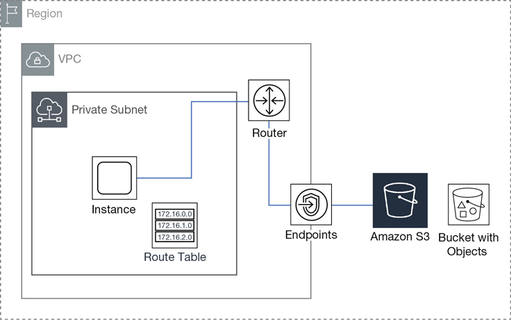
A private VPC gateway endpoint sits in the middle of the source and destination acting as a secure tunnel connection; for example, the S3 gateway connection sits between the instance running a Web application and the S3 data location. S3 and DynamoDB are still accessed utilizing their public IP address location; however, each service is connected directly to the VPC through the private endpoint connection. This may sound confusing. You may be thinking, why don’t the gateway services being accessed have a private IP address connection? The path across the endpoint is private, but the destination address doesn’t change. However, it’s accessed by a private network connection rather than a public connection. Here are steps for creating a gateway endpoint:
From the VPC console, select Endpoints, Create Endpoint.
Select the desired gateway endpoint (Amazon S3, DynamoDB, or other options if available).
Select the VPC and subnets where access is required.
Select the route table.
Modify the default endpoint policy to match security needs.
Update the security groups and network ACLs as necessary.
Endpoint policies are used to define the endpoint access rules and, as mentioned, these policies are IAM resource policies that are established when the endpoint is being created. The default policy allows full access to the service; this is one of those defaults that should be evaluated and changed if necessary.
Note that the defined endpoint policy does not overrule any IAM user policies or S3 bucket policies that are in force. Instead, endpoint policies are controlling access from the VPC through the endpoint to the service from the instance, as shown in Figure 3-28. This resource policy is using a condition defined by the statement aws:sourcevpc, which defines the specific VPC that is only allowed access to specific resources.
![CLI program for controlling access: {"Version": "2012-10-17", "Id": "Policy1415115669152", "Statement": [ "Sid": "Access-from-specific-VPC-only", "Principal": "*", "Action": "s3:*", "Effect": "Deny", "Resource": "expenses": { "aws:sourceVpc": "vpc-111bbb22"}]}](http://images-20200215.ebookreading.net/5/4/4/9780135301104/9780135301104__learning-amazon-web__9780135301104__graphics__03fig28.jpg)
Interface VPC Endpoints
The newest form of a VPC endpoint supported by AWS is denoted by the term interface powered by technology called PrivateLink. The “interface” is a network adapter designated with a private IP address. Not all AWS services are yet supported by interface endpoint connections; however, the long-term goal is to make all AWS services accessible through private interface endpoints.
AWS resources with an interface connection appear to be in your VPC because they are accessed using a private IP address from the linked VPC. If PrivateLink resources are being utilized in a VPC with multiple AZs, multiple private IP addresses will be used, one IP address per availability zone. For customers using Direct Connect to link their on-premise data center with AWS resources, there is also a bonus: AWS-hosted data records and other services can be accessible from your on-premise network.
A Terra Firma developer could sit in his office at work developing applications; the key component, the data records, are being accessed privately during development across the fiber Direct Link connection, as shown in Figure 3-29. Once the application is finished and in production, both the application and data records can continue to be accessed privately through the interface connection from the head office.
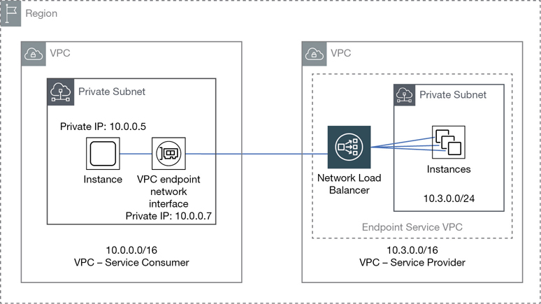
There’s an elastic IP address, defined as a private static IP address behind every interface connection. Until the PrivateLink service was introduced, an EIP was always defined as a static public IP address. An EIP is now defined as either a static public or a static private IP address, depending on the AWS service.
Most large corporations considering a move to the cloud have massive levels of paranoia when it comes to their data records being stored in the cloud and accessed publicly. In addition, some applications are not going to move to the public cloud anytime soon. For many corporations, the only cloud design that’s acceptable is a private hybrid design. PrivateLink endpoint connections combined with high-speed 10 Gbps Direct Connect connections delivers speed, security, and AWS services in a totally private environment. Direct Connect is discussed at the end of this chapter.
Note
Current private endpoints to AWS services includes Kinesis, EC2 Instances, ELB, EC2 Systems Manager, KMS, and Service Catalog, with many more AWS services due to be supported soon.
With no public connectivity, the AWS services that are being accessed using PrivateLink are fully protected from any public attacks, including DDoS attacks because the private interface endpoints are just not reachable from the Internet. When you create an endpoint inside your VPC, the service names are protected because Route 53 DNS services send you to the private endpoint location, ignoring any public routes that also may be advertised. Private endpoints also have regional zonal names designed for keeping traffic within the region, which allows customers to isolate traffic within a specific AZ. Zonal endpoints could also potentially save you additional data transfer charges and latency issues.
The hardware powering interface endpoints is publicly called PrivateLink but internally, AWS calls this new network hardware HyperPlane, which is a massively scalable fault-tolerant distributed system designed for managing VPC network connections. It resides in the fabric of the VPC networking layer, where AWS’s software-defined networking is deployed and it’s able to make transactional decisions in microseconds. When a VPC interface endpoint is created, it is associated with several virtual hyperplane nodes that intercept network communications at the VPC networking layer and quickly decide what to do with each request. If the request is made to a private endpoint, the transactional decision and the shared state are applied in milliseconds.
Endpoint Services with PrivateLink
Using the PrivateLink technology, AWS hopes to help provide private SaaS services to corporations, as shown in Figure 3-30. The owner of each private SasS service is defined as a service provider and the owner of the interface endpoint the service consumer; the consumer of the service. Private SaaS services could include monitoring service and disaster recovery services. There really is no limit to the possibilities that are being developed and offered.
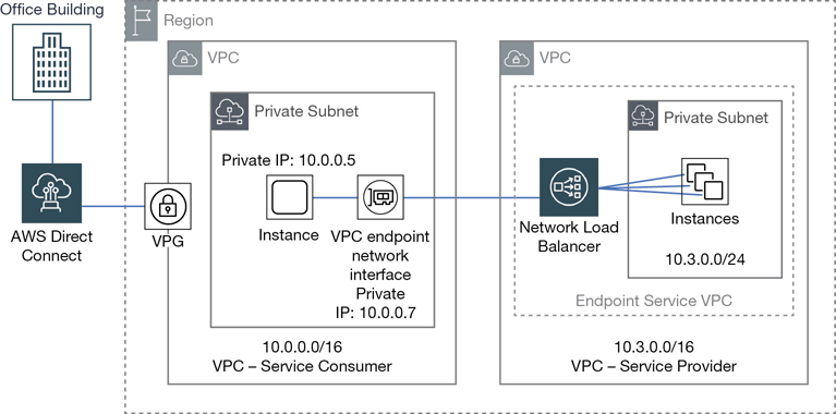
The customer who wants to access the service makes a request to the vendor; once that request is accepted, a peering connection is established with the customer’s VPC. Now the customers can access the service provider’s service through the peering connection. To handle access to the subscribed service, behind the “interface” connection is a private Network Load Balancer (NLB) positioned at the entrance hosted service. Third-party micro-service architectures could also be hosted within a private VPC. To the client it’s a micro-service, to the service vendor it’s a massive fault-tolerant service that scales and fails over as necessary. The service provider VPC can follow the same best practices as recommended by AWS for creating fault-tolerant applications hosted in a VPC. This exact process is how Amazon provides load-balancing services to multiple customers within each region. Applications can be designed with availability targets located in each AZ.
Depending on the tenancy requirements of the customer, for a single-tenant mode of operation, a private NLB could be created for every client customer. Multitenant designs could allow multiple customers to use the same NLB service. There are several additional choices available to separate endpoint traffic from VPCs in a multitenant design:
Use separate account/password security tokens at the application level.
Use separate Network Load Balancers (NLB) and different listener ports.
Utilize the ProxyProtocolV2 preamble, which adds a header to each connection that lists the ID of the destination endpoint.
Note
The costs for PrivateLink are split between the provider and the customer. The provider side pays for the NLB costs. The client side pays for PrivateLink endpoint costs.
The steps for creating an Interface PrivateLink endpoint follow:
From the VPC console, select Endpoint Services, Create Endpoint.
Select the desired Interface endpoint.
Select the VPC and subnets where access is required.
Select Enable Private DNS Name if required.
Select Security Group.
Update route tables, security groups, and network ACLs as necessary.
VPC Connectivity
Connecting a VPC to an external location requires the creation of a public door for direct Internet access, a private door for private access to your corporate data center, or perhaps a private endpoint, which allows connectivity with other VPCs or service providers. We’ve already talked about peering and endpoints; let’s look at public and private connectivity starting with connections to the Internet using the Internet gateway (IGW) service.
Internet Gateway: The Public Door
Before traffic can flow to or from the Internet for Instances hosted on a public subnet within a VPC you must attach an Internet gateway (IGW) to the desired VPC. At AWS, an IGW is hosted by a massive horizontally scaled and highly available server: the standard AWS design criteria farm composed of custom hardware devices AWS calls Blackfoot devices. The IGW service is an example of a hosted micro-service. You may first quibble with this definition, but when you order an IGW, that’s exactly what you are ordering: a tiny chunk of the overall IGW service itself. You don’t know how the IGW exactly works, and you don’t really need to know all the fine details other than it works and continues to work. This mind-set is the same for any service that you order from Amazon, whether you are ordering a gateway service, the ELB services, or auto scaling; we are ordering a service and expect it to function as advertised.
After creation, you need to associate the IGW service with the desired VPC, as shown in Figure 3-31. The IGW still won’t be accessible until your route tables have been updated with a route to allow the appropriate subnets to send their public traffic to the IGW. Typically, the default destination route assigned to an Internet gateway is 0.0.00/0, which may be fine for a public-facing application available to the public. However, you can narrow the scope of access to a specific range of public IP addresses from your company, other elastic IP addresses, or specific BYOIP addresses. Public traffic that flows through the IGW also has an additional layer of protection because NAT is performed on all outgoing public traffic from instances with public IP addresses communicating across the Internet.
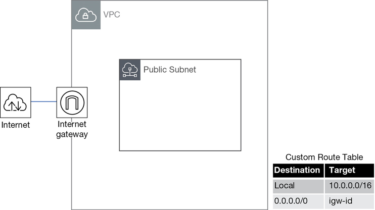
As we have discussed, if the default VPC is used, the IGW is already enabled and set up with a route table entry for the public subnets. In addition, using either of the first two options to create public subnets with the Launch VPC Wizard from the VPC console creates the public subnets, attaches an IGW, and adds route table entries for the IGW to the main route table.
Note
Subnets associated with a route table pointing to an Internet gateway are always public subnets.
Egress-Only Internet Gateway
If you require outbound communication over IPv6 from your instances to the Internet using IPv6, you can use an egress-only Internet gateway (EOIG), as shown in Figure 3-32. Internally, the EOIG is a horizontally-scaled, redundant, and highly available service that allows outbound communication over IPv6 but prevents any communication from the Internet from initiating an IPv6 connection with your instances. The design of the EOIG is stateful, meaning that traffic that is forwarded from an instance to the Internet will have its traffic forwarded back to the instance that made the request.
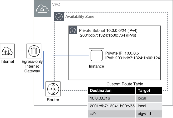
VPN Connections
It’s entirely possible that requiring public access for AWS resources is not part of your network design. Many companies design solutions utilizing a private hybrid design, where their corporate data center is securely connected to the AWS cloud without using the Internet as a public communication medium.
Using a VPN connection to connect to your VPC provides a high level of security using an IPsec VPN connection. A VPN connection is a site-to-site tunnel connection between your VPC and your corporate network. But before your VPN connections can be set up and connected from your corporate data center to a VPC from your remote network, you need to attach a “private door,” called a virtual private gateway (VPG), that is directly attached to the VPC where access is desired.
Note
Both the IGW and the VPG are directly attached to the VPC.
Just the attaching of the VPG does not provide access; you still must manually add access to the VPG through a route table entry before access is allowed. Routing types supported are either static routes or dynamic routes across a VPN tunnel using the border gateway protocol (BGP). VPN connections with a single static route won’t have a failover option, as shown in Figure 3-33.
Dynamically routed VPN connections can reroute traffic as necessary to other available routes. Adhering to Amazon’s standards of redundancy, each VPN connection is created with two VPN endpoints on the Amazon side, and each tunnel is assigned with a unique public IP address. IPv4 IPsec VPNs are supported; currently, IPv6 VPN connections are not supported.
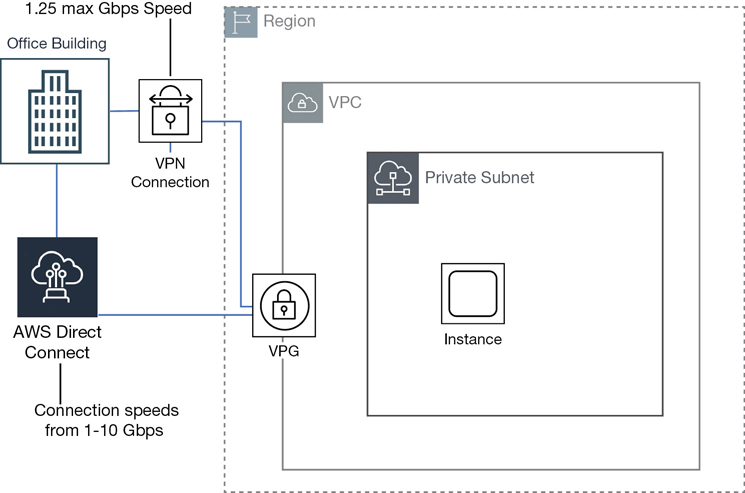
Note
There are two choices when connecting your data center to AWS:
A secure VPN connection
A fast and secure connection using a Direct Connect high-speed private connection
Virtual Private Gateway
You need to understand several components before you create and complete your VPN connections. The virtual private gateway, the customer gateway, and the VPN connection are shown in Figure 3-34.
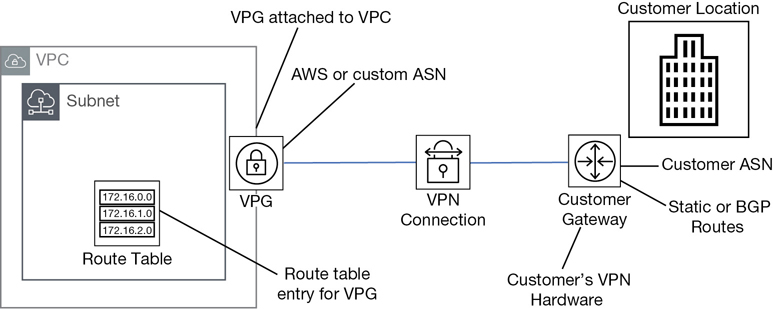
The VPG is the VPN concentrator on the Amazon side of the connection closest to the VPC. During the configuration of a VPG connection, you can accept the default private anonymous system number (ASN) provided by AWS or specify your own custom number. After creation, the VPG needs to be attached to the desired VPC, and appropriate routes need to be added to the route tables to enable communication with the VPG.
Customer Gateway
On the opposite side of the VPN connection, on the customer side, resides the customer gateway. Most customers use a hardware device for their VPN connections, although you could use a software appliance. A key concept: the only hardware in a VPN connection is on the customer side of the connection. Configuration steps for most popular customer hardware are typically provided by AWS; there are many popular supported devices complete with the required configuration information. Examples of devices that AWS supports include Cisco, Checkpoint, Fortinet, Juniper, and Palo Alto. Check the VPC FAQ at AWS for current details on the devices supported as evidence that additional devices are ever changing.
When creating a customer gateway, you need to enter the public IP address location of your hardware device and indicate the type of routing to be used: either static or dynamic. If you choose dynamic, you need to enter your ASN for BGP communications. If your customer gateway is behind a NAT device, you need the public IP address of the NAT device. Once connections are complete on the customer and the AWS side, traffic generated from the customer side of the VPN connection initiates the VPN tunnel, as shown in Figure 3-35. Before creating a VPN connection, the customer gateway needs to be created.
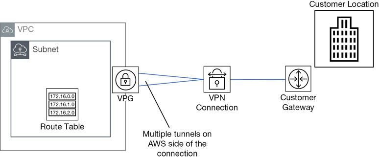
Note
The maximum IPsec VPN throughput at AWS is 1.25 GB per second.
VPN Connections
When a VPN connection is created, you are prompted to download the configuration file that matches your customer gateway device. Information contained in the document includes device and tunnel configuration. When choosing VPN routing, the best option is to choose dynamic routing using BGP sessions. BGP-capable devices fail over to the second VPN tunnel on the AWS side if the first tunnel goes down.
You can specify the range of inside IP addresses inside the VPN tunnel using the /30 CIDR block from the 169.254.0.0 /16 range. The chosen pre-shared key (PSK) can be between 8 and 64 characters but can’t start with a zero (0). If you change your mind about the inside tunnel IP address or the PSK you have selected after you have created your VPN connection, you must delete the VPN connection and create a new one. Modifications are not allowed for existing VPN connections.
A VPN connection at AWS is managed. There are several features to be aware of when creating a VPN connection:
NAT-T NAT traversal is supported.
4-byte ASN numbers are supported.
Cloud Watch metrics include TunnelState, TunnelDataIn, and TunnelDataOut.
Encryption options include AES 256-bit, SHA-2 hashes, and DH groups.
Tunnel options are customized for inside IP addresses and PSK values.
Custom private ASN numbers are on the Amazon side of a BGP session.
VPN CloudHub
If you have multiple customer locations, you can choose the AWS VPN CloudHub. Multiple remote sites can communicate with the VPC and with each other. CloudHub design follows the traditional hub-and-spoke model. CloudHub is not a new connection feature, and there’s no additional speed added because each multiple connection is a separate connection. But it does work and may be an option if your branch offices are small.
On the AWS side, there is still a single virtual private gateway; however, there are multiple customer gateways due to the multiple connection paths shown in Figure 3-36. Each customer gateway needs a unique BGP ASN number to differentiate its location, and each site can have overlapping IP ranges. Remember, the bandwidth of the VPN connection is not that fast. It maxes out at 1.25 Gbps.
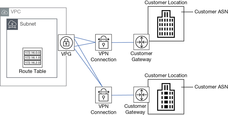
Understanding Route Propagation
After route table entries have been created allowing EC2 instances to communicate with VPN connections from the customer gateway, you can enable the automatic provisioning of the available routes through a process called route propagation. To enable automatic route propagation, from the properties of the route table, choose the Route Propagation tab, and then select the VPG to assign to the route table.
If static routes are available, when a VPN connection is activated, the static addresses for your customer data center and the CIDR ranges for the connected VPC are automatically added to the route table. Each VPN connection created in AWS will have two tunnels designed for failover on the Amazon side of the connection. Each tunnel will have a unique security association (SA) that identifies each tunnel’s inbound and outbound traffic.
Therefore, there are four SAs for the design that uses the default VPN connection of two endpoints on the AWS side with two unique tunnel connections at AWS, and a single connection on the customer side. For this example, any traffic from your network can access any CIDR range on your VPN. To better control your traffic, you can choose to use dynamic routes with tunnels that you define. If dynamic routing is in place, the defined BGP advertisements are automatically added to the route table.
Direct Connect
The purpose of AWS Direct Connect is to connect your internal corporate network to a Direct Connect (DC) location over a private high-speed fiber connection with no Internet connection. This high-speed highway can be ordered with port speeds up to 10 Gbps. There are a range of other slower speeds available from other partners supporting Direct Connect connections.
Each DC connection ordered is a single dedicated connection from your routers to the routers at AWS. If a DC second connection is ordered, it is also provisioned on redundant Amazon routers. If a DC connection fails, traffic fails over to the second DC link automatically. This is an expensive option, but perhaps desired availability makes this an option worth considering.
Direct connections only support 1000BASE-LX or 10GBASE-LR connections over single-mode fiber using the Ethernet transport, using 1310nm connectors.
The connection itself is made using a single fiber pair running from a physical piece of customer equipment that must be in the same facility as the AWS Direct Connect inter-connect.
The hosted connections are connections provided by the AWS Direct Connect Partner from the customer data center to the facility where AWS “Direct Connections” can be made. The available types of connection to the Amazon partner from the customer site is totally up to what is supported by the Amazon partner.
After a DC connection is in place, you can create virtual interfaces to a public AWS service such as S3 buckets or connect privately to a VPC.
To sign up for Direct Connect, from the console, complete the following steps:
Request a connection, specifying the port speed and the Direct Connect location where the connection will be terminated. If your port speed is less than 1 Gbps, you must contact an APN partner in your geographical location and order a hosted connection at the bandwidth you desire. Once this connection is completed, the setup of Direct Connect can continue in the console.
Once AWS has approved your connection, a letter of authorization and connecting facility assignment (LOA-CFA) can be downloaded and presented to your provider authorizing them to create a network connection to AWS; this is typically called a cross-connect.
Create virtual interfaces for connections to either your VPC or to a public service not hosted in the VPC.
After virtual interfaces have been created, download the router configuration file, which contains router configuration information to successfully connect to either your private or your public virtual interface.
This is a complicated topic for this book; only the big-picture summary is being provided here. There are many considerations for Direct Connect, including your location, the AWS region you are operating in, the level of redundancy required, and many available options depending on the number of VPCs, public AWS services, or Direct Connect gateways that you may want to connect, as shown in Figure 3-37.
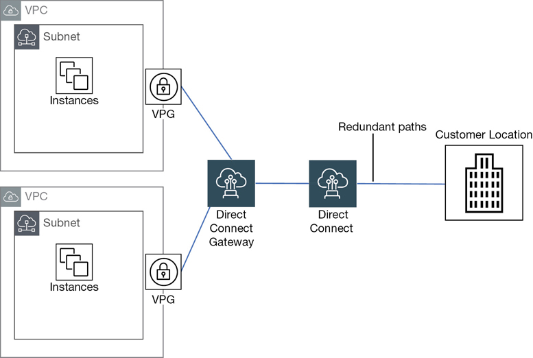
Route 53
Route 53 is Amazon’s DNS service and, of course, it’s highly scalable and highly available. Its primary job is to route your end users to hosted applications at AWS. These applications and resources are typically hosted behind AWS services with DNS names that are stored and referenced through Route 53, such as an ELB load balancer, CloudFront, Amazon’s CDN, or S3 bucket. Domain names can also be registered with Route 53 directly, or, domain names can be transferred from other registrars. Amazon is also a reseller of the registrar Gandi. Domain names can be transferred to and managed by Route 53.
Route 53 also manages your public DNS records that are connected to public IP addresses; these can be from the short-term public IP address pool provided by AWS, and elastic IP addresses, BYOIP public address ranges, and domain names that are hosted at AWS.
In addition to standard DNS services, Route 53 offers health checking and traffic-steering services for routing selected traffic to a healthy endpoint in multiple AWS regions.
You can also use Route 53 to host a private domain that you’ve created within a VPC. Each private hosted domain’s zone information is assigned to four virtual Route 53 name servers that store the DNS records for your domain.
If you want to migrate from another third-party DNS service provider, exporting your current DNS settings to their own file allows you to import your records into Route 53. Keep in mind that the imported zone file must be empty except for the default NS and SOA records. And DNS is a funny world; if your records are not in a standard BIND format, strictly adhering to RFC 1034 and 1035, there could be migration issues.
Note
By default, each Route 53 account is assigned a soft limit of 500 hosted zones and 10,000 resource record sets per hosted zone; you can increase these values upon request.
Amazon supports a DNS record type called an Alias record. Alias records map resource records within your hosted zone to a variety of AWS services including ELB, CloudFront distributions, and Elastic Beanstalk environments. Alias records also allow you to route traffic from one record within a hosted zone to another record. Alias records as detailed in Table 3-12 work internally like a CNAME record, where DNS domain names are mapped to the desired target resource. However, the interesting difference between an alias record and a CNAME record, as shown in Figure 3-38, is that alias records can contain multiple records associated with a single resource name.
Table 3-12 Alias Records vs CNAME at AWS
CNAME Record |
Alias Record |
|---|---|
Not supported for zone apex record |
Supported for zone apex record |
Route 53 charges for CNAME queries |
No charge for alias |
Queries are always re-directed |
Name and type of alias record must match |
Points to any DNS record |
Points only to AWS resources |
nslookup shows CNAME record |
Alias shows as record type (A, AAAA) |
Alias records are also used to point your zone apex (your registered root domain name) to a variety of AWS services, including load balancers, static websites hosted by an S3 bucket, and CloudFront distributions. The resources for each of these services can change due to the scaling up or down of the compute resources of each redundant service. With alias records, Route 53 has the changes covered.
For example, the target resource could be a load balancer or a CloudFront distribution. As you know, the load balancer service is designed for failover. As a result, when Route 53 receives a query for a load balancer, an alias record is used to point to the load-balancing resource. Using an alias record allows Route 53 to respond if necessary with more than one IP address for the load-balancing service in times of internal changes to the service. What happens when we query a CloudFront distribution? The alias record provides Route 53 with additional redundancy as multiple records pointing to the multiple IP addresses for the edge servers for accessing your content can be provided, as shown in Figure 3-38.

Using a CNAME instead of an Alias record, only one DNS record could be referenced per service. Route 53 automatically recognizes any changes in the AWS resource when alias records are used to route traffic. Back to our load-balancing example: if your load-balancer fails, Route 53 automatically sends traffic to another load balancer’s IP address.
In addition, CNAMEs queries at AWS cost you money; when querying AWS resources using alias records, there’s no charge. However, at Amazon an alias record only points to a supported AWS resource or to another DNS record within the hosted zone where the alias record has been created.
Route 53 Routing Options
Route 53 supports a variety of routing protocols, including weighted round robin (WRR), latency-based routing (LBR), and Geo DNS, as shown in Table 3-13.
WRR allows you to assign weights to resource record sets. Changing the weight of one record in a set of records to a higher number than the other records in the resource record set tells the end user that the resource with the higher number can take more traffic. Assigning values is complicated but is incredibly useful in routing traffic when desired from site A to site B.
LBR is utilized when you are balancing application performance across multiple regions. Record sets contain multiple AWS endpoints, and Route 53 will do the latency math and determine the best endpoint for the user request.
Geo DNS gets a little fancier and allows you to balance user requests to specific endpoints based on the geographical location the user request came from. Geo DNS relies on global records with multiple responses defined for all DNS queries. With Geo DNS, it is possible to customize the destination content to regions, and countries within each region. You can also control content based on language preferences, or in the case of compliance, define mandated endpoint locations.
Table 3-13 Route 53 Routing Options
Routing Options
Details
Simple
For a single resource; a Web instance
Failover
Active-passive failover; from one resource to another
Geolocation
Route traffic based on user’s location
Geo-proximity
Route traffic based on location of resources
Latency
Route traffic to AWS resources with the least latency
Multi-value answer
Answer queries with multiple healthy records
Weighted routing
Route a percentage of traffic to resources; Blue-Green
Each of these routing protocols can be combined in a custom traffic policy design that Amazon calls Traffic Flow. Policies can also pinpoint resource location based on the exact physical location using static IP addresses.
Route 53 Health Checks
What’s the point of having DNS records that point to resources that are not functional? That’s why there’s a need for health checks and failover. Route 53 constantly verifies that your applications are reachable and available through health checks. When health checks fail, requests for resources fail over to the alternate location.
Alias records created with the Evaluate Target Health parameter set to true that point to a load balancer DNS name result in Route 53 managing the health check of the load balancer automatically. Health checks are using DNS names, not IP addresses; for a hosted cloud service, IP addresses are always going to change. But we don’t worry about these changes when they occur because we are using DNS names and not IP addresses.
DNS failover can also point to a backup site location such as an S3 bucket or an external location when your VPC becomes unavailable for whatever reason, as shown in Figure 3-39. Internally, Route 53 monitors failed endpoints; once a failed endpoint passes its health check, Route 53 updates its DNS records accordingly. Health checks are supported for HTTPS, HTTP, and TCP. Health checks can also be carried out using the built-in monitoring service CloudWatch using many defined metrics.
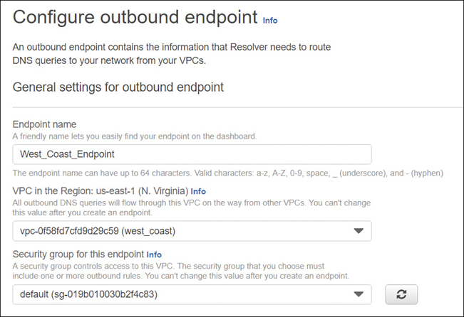
Using DNS with a VPC: Private DNS Zones
Route 53 allows you to have authoritative DNS services hosted within your VPCs with no Internet exposure. After creating a private hosted zone, Route 53 only returns records when queried from within the associated VPCs. Route 53 health checks are also supported for resource record sets within each private DNS hosted zone.
If you want to route traffic for one of your domains and its subdomains that are contained within a VPC, the first task is to create a private hosted zone in Route 53. Within the private zone, you then create Resource record sets that list the resources that Route 53 will direct queries for your domain to. To use a private hosted zone with the VPC, the following settings must be set to true:
enableDNSHostnames
enableDnsSupport
DNS Hostnames
Each custom VPC has attributes for DNS that can be customized. The defaults, or the attributes that will be applied, depend on how the VPC was created. One of the words most overused at AWS is default.
If you are using the main VPC Wizard located on the VPC Dashboard, both VPC DNS attributes are set to true.
If you use the AWS CLI or use the VPC link displayed on the Your VPCs landing page Wizard to create the VPC, the attributes are defined differently, as shown in Table 3-14. These attributes determine whether each instance receives a public DNS hostname and if DNS resolution using Route 53 is supported.
Table 3-14 DNS VPC Attributes
VPC DNS Attribute |
Default VPC |
CLI, API, or AWS SDK |
Your VPC Wizard |
VPC Wizard |
|---|---|---|---|---|
Enable DNS hostname (Public) |
True |
False |
False |
True |
Enable DNS support |
True |
True |
True |
True |
If both attributes in Table 3-14 are set to true, your instance receives a public DNS hostname, and Route 53 resolves any Amazon-provided private DNS hostnames.
If either or both attributes in Table 3-14 are false, your instance will not receive a public DNS hostname, and Route 53 will not resolve the private DNS hostname provided by Amazon.
If you have private IP addresses provided by AWS, the private DNS hostname resolves to the private IPv4 address of the instance. The private DNS hostname can be used to communicate between instances hosted on the same network.
If you are using the default VPC to deploy instances into, each instance will have a public and private DNS hostname that will correspond to the public and private IPv4 addresses assigned to the instance. Keep in mind that Route 53 is responsible for routing requests to specific domains and applications hosted at AWS. Best practice is that user requests should be routed to a load balancer and not directly to the instance. Therefore, DNS resolution directly to the instance is not required.
In Conclusion
Whew. Okay, this was a long chapter, but I don’t really think there’s anything we could’ve cut out for understanding of networking at AWS. Certainly, we could go a lot deeper, but it’s important to get the bedrock architecture components understood. Then you can sit back and think about what you are doing with networking in your own data center and how that differentiates between what you’re going to have to do at AWS. You can’t call up AWS folks and say, “Hey, I’m not doing it your way.” That’s a short one-sided conversation. Make sure to watch the companion videos to get more details on network deployment at AWS. Then look at the discussion points with your trusted team of tech experts or people at work who are going to be making these types of decisions. And start asking some of these questions out loud and finding out what the answers are from your company’s point of view.
Top 10 Discussion Points: Networking Considerations for Security, Failover, and Connectivity
Review this list and then ask the questions out loud. Discuss. Argue. Compromise. Agree or disagree. Only then will you know the real answers.
What IP address ranges should I use for my VPC?
Why do I need more than one VPC?
Why am I using public subnets for my Web servers?
Do I have existing Public IP addresses that can be moved to AWS?
What AWS networking services can replace existing hardware devices?
Are my VPN hardware devices compatible with AWS?
Have I finished constructing my security groups required for my two tier or three-tier application?
Do I have to use network ACLs to conform with my compliance rules and regulations?
Do I have to use elastic IP addresses?
Would Direct Connect help my hybrid design connectivity?