
Chapter 12
Startup and shutdown
In this chapter, we describe the steps required to boot Windows and the options that can affect system startup. Understanding the details of the boot process will help you diagnose problems that can arise during a boot. We discuss the details of the new UEFI firmware, and the improvements brought by it compared to the old historical BIOS. We present the role of the Boot Manager, Windows Loader, NT kernel, and all the components involved in standard boots and in the new Secure Launch process, which detects any kind of attack on the boot sequence. Then we explain the kinds of things that can go wrong during the boot process and how to resolve them. Finally, we explain what occurs during an orderly system shutdown.
Boot process
In describing the Windows boot process, we start with the installation of Windows and proceed through the execution of boot support files. Device drivers are a crucial part of the boot process, so we explain how they control the point in the boot process at which they load and initialize. Then we describe how the executive subsystems initialize and how the kernel launches the user-mode portion of Windows by starting the Session Manager process (Smss.exe), which starts the initial two sessions (session 0 and session 1). Along the way, we highlight the points at which various on-screen messages appear to help you correlate the internal process with what you see when you watch Windows boot.
The early phases of the boot process differ significantly on systems with an Extensible Firmware Interface (EFI) versus the old systems with a BIOS (basic input/output system). EFI is a newer standard that does away with much of the legacy 16-bit code that BIOS systems use and allows the loading of preboot programs and drivers to support the operating system loading phase. EFI 2.0, which is known as Unified EFI, or UEFI, is used by the vast majority of machine manufacturers. The next sections describe the portion of the boot process specific to UEFI-based machines.
To support these different firmware implementations, Windows provides a boot architecture that abstracts many of the differences away from users and developers to provide a consistent environment and experience regardless of the type of firmware used on the installed system.
The UEFI boot
The Windows boot process doesn’t begin when you power on your computer or press the reset button. It begins when you install Windows on your computer. At some point during the execution of the Windows Setup program, the system’s primary hard disk is prepared in a way that both the Windows Boot Manager and the UEFI firmware can understand. Before we get into what the Windows Boot Manager code does, let’s have a quick look at the UEFI platform interface.
The UEFI is a set of software that provides the first basic programmatic interface to the platform. With the term platform, we refer to the motherboard, chipset, central processing unit (CPU), and other components that compose the machine “engine.” As Figure 12-1 shows, the UEFI specifications provide four basic services that run in most of the available CPU architectures (x86, ARM, and so on). We use the x86-64 architecture for this quick introduction:
■ Power on When the platform is powered on, the UEFI Security Phase handles the platform restart event, verifies the Pre EFI Initialization modules’ code, and switches the processor from 16-bit real mode to 32-bit flat mode (still no paging support).
■ Platform initialization The Pre EFI Initialization (PEI) phase initializes the CPU, the UEFI core’s code, and the chipset and finally passes the control to the Driver Execution Environment (DXE) phase. The DXE phase is the first code that runs entirely in full 64-bit mode. Indeed, the last PEI module, called DXE IPL, switches the execution mode to 64-bit long mode. This phase searches inside the firmware volume (stored in the system SPI flash chip) and executes each peripheral’s startup drivers (called DXE drivers). Secure Boot, an important security feature that we talk about later in this chapter in the “Secure Boot” section, is implemented as a UEFI DXE driver.
■ OS boot After the UEFI DXE phase ends, execution control is handed to the Boot Device Selection (BDS) phase. This phase is responsible for implementing the UEFI Boot Loader. The UEFI BDS phase locates and executes the Windows UEFI Boot Manager that the Setup program has installed.
■ Shutdown The UEFI firmware implements some runtime services (available even to the OS) that help in powering off the platform. Windows doesn’t normally make use of these functions (relying instead on the ACPI interfaces).

Figure 12-1 The UEFI framework.
Describing the entire UEFI framework is beyond the scope of this book. After the UEFI BDS phase ends, the firmware still owns the platform, making available the following services to the OS boot loader:
■ Boot services Provide basic functionality to the boot loader and other EFI applications, such as basic memory management, synchronization, textual and graphical console I/O, and disk and file I/O. Boot services implement some routines able to enumerate and query the installed “protocols” (EFI interfaces). These kinds of services are available only while the firmware owns the platform and are discarded from memory after the boot loader has called the ExitBootServices EFI runtime API.
■ Runtime services Provide date and time services, capsule update (firmware upgrading), and methods able to access NVRAM data (such as UEFI variables). These services are still accessible while the operating system is fully running.
■ Platform configuration data System ACPI and SMBIOS tables are always accessible through the UEFI framework.
The UEFI Boot Manager can read and write from computer hard disks and understands basic file systems like FAT, FAT32, and El Torito (for booting from a CD-ROM). The specifications require that the boot hard disk be partitioned through the GPT (GUID partition table) scheme, which uses GUIDs to identify different partitions and their roles in the system. The GPT scheme overcomes all the limitations of the old MBR scheme and allows a maximum of 128 partitions, using a 64-bit LBA addressing mode (resulting in a huge partition size support). Each partition is identified using a unique 128-bit GUID value. Another GUID is used to identify the partition type. While UEFI defines only three partition types, each OS vendor defines its own partition’s GUID types. The UEFI standard requires at least one EFI system partition, formatted with a FAT32 file system.
The Windows Setup application initializes the disk and usually creates at least four partitions:
■ The EFI system partition, where it copies the Windows Boot Manager (Bootmgrfw.efi), the memory test application (Memtest.efi), the system lockdown policies (for Device Guard-enabled systems, Winsipolicy.p7b), and the boot resource file (Bootres.dll).
■ A recovery partition, where it stores the files needed to boot the Windows Recovery environment in case of startup problems (boot.sdi and Winre.wim). This partition is formatted using the NTFS file system.
■ A Windows reserved partition, which the Setup tool uses as a fast, recoverable scratch area for storing temporary data. Furthermore, some system tools use the Reserved partition for remapping damaged sectors in the boot volume. (The reserved partition does not contain any file system.)
■ A boot partition—which is the partition on which Windows is installed and is not typically the same as the system partition—where the boot files are located. This partition is formatted using NTFS, the only supported file system that Windows can boot from when installed on a fixed disk.
The Windows Setup program, after placing the Windows files on the boot partition, copies the boot manager in the EFI system partition and hides the boot partition content for the rest of the system. The UEFI specification defines some global variables that can reside in NVRAM (the system’s nonvolatile RAM) and are accessible even in the runtime phase when the OS has gained full control of the platform (some other UEFI variables can even reside in the system RAM). The Windows Setup program configures the UEFI platform for booting the Windows Boot Manager through the settings of some UEFI variables (Boot000X one, where X is a unique number, depending on the boot load-option number, and BootOrder). When the system reboots after setup ends, the UEFI Boot Manager is automatically able to execute the Windows Boot Manager code.
Table 12-1 summarizes the files involved in the UEFI boot process. Figure 12-2 shows an example of a hard disk layout, which follows the GPT partition scheme. (Files located in the Windows boot partition are stored in the WindowsSystem32 directory.)
Table 12-1 UEFI boot process components
Component |
Responsibilities |
Location |
|---|---|---|
bootmgfw.efi |
Reads the Boot Configuration Database (BCD), if required, presents boot menu, and allows execution of preboot programs such as the Memory Test application (Memtest.efi). |
EFI system partition |
Winload.efi |
Loads Ntoskrnl.exe and its dependencies (SiPolicy.p7b, hvloader.dll, hvix64.exe, Hal.dll, Kdcom.dll, Ci.dll, Clfs.sys, Pshed.dll) and bootstart device drivers. |
Windows boot partition |
Winresume.efi |
If resuming after a hibernation state, resumes from the hibernation file (Hiberfil.sys) instead of typical Windows loading. |
Windows boot partition |
Memtest.efi |
If selected from the Boot Immersive Menu (or from the Boot Manager), starts up and provides a graphical interface for scanning memory and detecting damaged RAM. |
EFI system partition |
Hvloader.dll |
If detected by the boot manager and properly enabled, this module is the hypervisor launcher (hvloader.efi in the previous Windows version). |
Windows boot partition |
Hvix64.exe (or hvax64.exe) |
The Windows Hypervisor (Hyper-V). Depending on the processor architecture, this file could have different names. It’s the basic component for Virtualization Based Security (VBS). |
Windows boot partition |
Ntoskrnl.exe |
Initializes executive subsystems and boot and system-start device drivers, prepares the system for running native applications, and runs Smss.exe. |
Windows boot partition |
Securekernel.exe |
The Windows Secure Kernel. Provides the kernel mode services for the secure VTL 1 World, and some basic communication facility with the normal world (see Chapter 9, “Virtualization Technologies”). |
Windows boot partition |
Hal.dll |
Kernel-mode DLL that interfaces Ntoskrnl and drivers to the hardware. It also acts as a driver for the motherboard, supporting soldered components that are not otherwise managed by another driver. |
Windows boot partition |
Smss.exe |
Initial instance starts a copy of itself to initialize each session. The session 0 instance loads the Windows subsystem driver (Win32k.sys) and starts the Windows subsystem process (Csrss.exe) and Windows initialization process (Wininit.exe). All other per-session instances start a Csrss and Winlogon process. |
Windows boot partition |
Wininit.exe |
Starts the service control manager (SCM), the Local Security Authority process (LSASS), and the local session manager (LSM). Initializes the rest of the registry and performs usermode initialization tasks. |
Windows boot partition |
Winlogon.exe |
Coordinates log-on and user security; launches Bootim and LogonUI. |
Windows boot partition |
Logonui.exe |
Presents interactive log on dialog screen. |
Windows boot partition |
Bootim.exe |
Presents the graphical interactive boot menu. |
Windows boot partition |
Services.exe |
Loads and initializes auto-start device drivers and Windows services. |
Windows boot partition |
TcbLaunch.exe |
Orchestrates the Secure Launch of the operating system in a system that supports the new Intel TXT technology. |
Windows boot partition |
TcbLoader.dll |
Contains the Windows Loader code that runs in the context of the Secure Launch. |
Windows boot partition |

Figure 12-2 Sample UEFI hard disk layout.
Another of Setup’s roles is to prepare the BCD, which on UEFI systems is stored in the EFIMicrosoftBootBCD file on the root directory of the system volume. This file contains options for starting the version of Windows that Setup installs and any preexisting Windows installations. If the BCD already exists, the Setup program simply adds new entries relevant to the new installation. For more information on the BCD, see Chapter 10, “Management, diagnostics, and tracing.”
All the UEFI specifications, which include the PEI and BDS phase, secure boot, and many other concepts, are available at https://uefi.org/specifications.
The BIOS boot process
Due to space issues, we don’t cover the old BIOS boot process in this edition of the book. The complete description of the BIOS preboot and boot process is in Part 2 of the previous edition of the book.
Secure Boot
As described in Chapter 7 of Part 1, Windows was designed to protect against malware. All the old BIOS systems were vulnerable to Advanced Persistent Threats (APT) that were using a bootkit to achieve stealth and code execution. The bootkit is a particular type of malicious software that runs before the Windows Boot Manager and allows the main infection module to run without being detected by antivirus solutions. Initial parts of the BIOS bootkit normally reside in the Master Boot Record (MBR) or Volume Boot Record (VBR) sector of the system hard disk. In this way, the old BIOS systems, when switched on, execute the bootkit code instead of the main OS code. The OS original boot code is encrypted and stored in other areas of the hard disk and is usually executed in a later stage by the malicious code. This type of bootkit was even able to modify the OS code in memory during any Windows boot phase.
As demonstrated by security researchers, the first releases of the UEFI specification were still vulnerable to this problem because the firmware, bootloader, and other components were not verified. So, an attacker that has access to the machine could tamper with these components and replace the bootloader with a malicious one. Indeed, any EFI application (executable files that follow the portable executable or terse executable file format) correctly registered in the relative boot variable could have been used for booting the system. Furthermore, even the DXE drivers were not correctly verified, allowing the injection of a malicious EFI driver in the SPI flash. Windows couldn’t correctly identify the alteration of the boot process.
This problem led the UEFI consortium to design and develop the secure boot technology. Secure Boot is a feature of UEFI that ensures that each component loaded during the boot process is digitally signed and validated. Secure Boot makes sure that the PC boots using only software that is trusted by the PC manufacturer or the user. In Secure Boot, the firmware is responsible for the verification of all the components (DXE drivers, UEFI boot managers, loaders, and so on) before they are loaded. If a component doesn’t pass the validation, an error message is shown to the user and the boot process is aborted.
The verification is performed through the use of public key algorithms (like RSA) for digital signing, against a database of accepted and refused certificates (or hashes) present in the UEFI firmware. In these kind of algorithms, two different keys are employed:
■ A public key is used to decrypt an encrypted digest (a digest is a hash of the executable file binary data). This key is stored in the digital signature of the file.
■ The private key is used to encrypt the hash of the binary executable file and is stored in a secure and secret location. The digital signing of an executable file consists of three phases:
Calculate the digest of the file content using a strong hashing algorithm, like SHA256. A strong “hashing” should produce a message digest that is a unique (and relatively small) representation of the complete initial data (a bit like a sophisticated checksum). Hashing algorithms are a one-way encryption—that is, it’s impossible to derive the whole file from the digest.
Encrypt the calculated digest with the private portion of the key.
Store the encrypted digest, the public portion of the key, and the name of the hashing algorithm in the digital signature of the file.
In this way, when the system wants to verify and validate the integrity of the file, it recalculates the file hash and compares it against the digest, which has been decrypted from the digital signature. Nobody except the owner of the private key can modify or alter the encrypted digest stored into the digital signature.
This simplified model can be extended to create a chain of certificates, each one trusted by the firmware. Indeed, if a public key located in a specific certificate is unknown by the firmware, but the certificate is signed another time by a trusted entity (an intermediate or root certificate), the firmware could assume that even the inner public key must be considered trusted. This mechanism is shown in Figure 12-3 and is called the chain of trust. It relies on the fact that a digital certificate (used for code signing) can be signed using the public key of another trusted higher-level certificate (a root or intermediate certificate). The model is simplified here because a complete description of all the details is outside the scope of this book.

Figure 12-3 A simplified representation of the chain of trust.
The allowed/revoked UEFI certificates and hashes have to establish some hierarchy of trust by using the entities shown in Figure 12-4, which are stored in UEFI variables:
■ Platform key (PK) The platform key represents the root of trust and is used to protect the key exchange key (KEK) database. The platform vendor puts the public portion of the PK into UEFI firmware during manufacturing. Its private portion stays with the vendor.
■ Key exchange key (KEK) The key exchange key database contains trusted certificates that are allowed to modify the allowed signature database (DB), disallowed signature database (DBX), or timestamp signature database (DBT). The KEK database usually contains certificates of the operating system vendor (OSV) and is secured by the PK.
Hashes and signatures used to verify bootloaders and other pre-boot components are stored in three different databases. The allowed signature database (DB) contains hashes of specific binaries or certificates (or their hashes) that were used to generate code-signing certificates that have signed bootloader and other preboot components (following the chain of trust model). The disallowed signature database (DBX) contains the hashes of specific binaries or certificates (or their hashes) that were compromised and/or revoked. The timestamp signature database (DBT) contains timestamping certificates used when signing bootloader images. All three databases are locked from editing by the KEK.

Figure 12-4 The certificate the chain of trust used in the UEFI Secure Boot.
To properly seal Secure Boot keys, the firmware should not allow their update unless the entity attempting the update can prove (with a digital signature on a specified payload, called the authentication descriptor) that they possess the private part of the key used to create the variable. This mechanism is implemented in UEFI through the Authenticated Variables. At the time of this writing, the UEFI specifications allow only two types of signing keys: X509 and RSA2048. An Authenticated Variable may be cleared by writing an empty update, which must still contain a valid authentication descriptor. When an Authenticated Variable is first created, it stores both the public portion of the key that created it and the initial value for the time (or a monotonic count) and will accept only subsequent updates signed with that key and which have the same update type. For example, the KEK variable is created using the PK and can be updated only by an authentication descriptor signed with the PK.
![]() Note
Note
The way in which the UEFI firmware uses the Authenticated Variables in Secure Boot environments could lead to some confusion. Indeed, only the PK, KEK, and signatures databases are stored using Authenticated Variables. The other UEFI boot variables, which store boot configuration data, are still regular runtime variables. This means that in a Secure Boot environment, a user is still able to update or change the boot configuration (modifying even the boot order) without any problem. This is not an issue, because the secure verification is always made on every kind of boot application (regardless of its source or order). Secure Boot is not designed to prevent the modification of the system boot configuration.
The Windows Boot Manager
As discussed previously, the UEFI firmware reads and executes the Windows Boot Manager (Bootmgfw.efi). The EFI firmware transfers control to Bootmgr in long mode with paging enabled, and the memory space defined by the UEFI memory map is mapped one to one. So, unlike wBIOS systems, there’s no need to switch execution context. The Windows Boot Manager is indeed the first application that’s invoked when starting or resuming the Windows OS from a completely off power state or from hibernation (S4 power state). The Windows Boot Manager has been completely redesigned starting from Windows Vista, with the following goals:
■ Support the boot of different operating systems that employ complex and various boot technologies.
■ Separate the OS-specific startup code in its own boot application (named Windows Loader) and the Resume application (Winresume).
■ Isolate and provide common boot services to the boot applications. This is the role of the boot libraries.
Even though the final goal of the Windows Boot Manager seems obvious, its entire architecture is complex. From now on, we use the term boot application to refer to any OS loader, such as the Windows Loader and other loaders. Bootmgr has multiple roles, such as the following:
■ Initializes the boot logger and the basic system services needed for the boot application (which will be discussed later in this section)
■ Initializes security features like Secure Boot and Measured Boot, loads their system policies, and verifies its own integrity
■ Locates, opens, and reads the Boot Configuration Data store
■ Creates a “boot list” and shows a basic boot menu (if the boot menu policy is set to Legacy)
■ Manages the TPM and the unlock of BitLocker-encrypted drives (showing the BitLocker unlock screen and providing a recovery method in case of problems getting the decryption key)
■ Launches a specific boot application and manages the recovery sequence in case the boot has failed (Windows Recovery Environment)
One of the first things performed is the configuration of the boot logging facility and initialization of the boot libraries. Boot applications include a standard set of libraries that are initialized at the start of the Boot Manager. Once the standard boot libraries are initialized, then their core services are available to all boot applications. These services include a basic memory manager (that supports address translation, and page and heap allocation), firmware parameters (like the boot device and the boot manager entry in the BCD), an event notification system (for Measured Boot), time, boot logger, crypto modules, the Trusted Platform Module (TPM), network, display driver, and I/O system (and a basic PE Loader). The reader can imagine the boot libraries as a special kind of basic hardware abstraction layer (HAL) for the Boot Manager and boot applications. In the early stages of library initialization, the System Integrity boot library component is initialized. The goal of the System Integrity service is to provide a platform for reporting and recording security-relevant system events, such as loading of new code, attaching a debugger, and so on. This is achieved using functionality provided by the TPM and is used especially for Measured Boot. We describe this feature later in the chapter in the “Measured Boot” section.
To properly execute, the Boot Manager initialization function (BmMain) needs a data structure called Application Parameters that, as the name implies, describes its startup parameters (like the Boot Device, BCD object GUID, and so on). To compile this data structure, the Boot Manager uses the EFI firmware services with the goal of obtaining the complete relative path of its own executable and getting the startup load options stored in the active EFI boot variable (BOOT000X). The EFI specifications dictate that an EFI boot variable must contain a short description of the boot entry, the complete device and file path of the Boot Manager, and some optional data. Windows uses the optional data to store the GUID of the BCD object that describes itself.
![]() Note
Note
The optional data could include any other boot options, which the Boot Manager will parse at later stages. This allows the configuration of the Boot Manager from UEFI variables without using the Windows Registry at all.
After the Application Parameters data structure has been built and all the boot paths retrieved (EFIMicrosoftBoot is the main working directory), the Boot Manager opens and parses the Boot Configuration Data file. This file internally is a registry hive that contains all the boot application descriptors and is usually mapped in an HKLMBCD00000000 virtual key after the system has completely started. The Boot Manager uses the boot library to open and read the BCD file. The library uses EFI services to read and write physical sectors from the hard disk and, at the time of this writing, implements a light version of various file systems, such as NTFS, FAT, ExFAT, UDFS, El Torito, and virtual file systems that support Network Boot I/O, VMBus I/O (for Hyper-V virtual machines), and WIM images I/O. The Boot Configuration Data hive is parsed, the BCD object that describes the Boot Manager is located (through its GUID), and all the entries that represent boot arguments are added to the startup section of the Application Parameters data structure. Entries in the BCD can include optional arguments that Bootmgr, Winload, and other components involved in the boot process interpret. Table 12-2 contains a list of these options and their effects for Bootmgr, Table 12-3 shows a list of BCD options available to all boot applications, and Table 12-4 shows BCD options for the Windows boot loader. Table 12-5 shows BCD options that control the execution of the Windows Hypervisor.
Table 12-2 BCD options for the Windows Boot Manager (Bootmgr)
Readable name |
Values |
BCD Element Code1 |
Meaning |
|---|---|---|---|
bcdfilepath |
Path |
BCD_FILEPATH |
Points to the BCD (usually BootBCD) file on the disk. |
displaybootmenu |
Boolean |
DISPLAY_BOOT_MENU |
Determines whether the Boot Manager shows the boot menu or picks the default entry automatically. |
noerrordisplay |
Boolean |
NO_ERROR_DISPLAY |
Silences the output of errors encountered by the Boot Manager. |
resume |
Boolean |
ATTEMPT_RESUME |
Specifies whether resuming from hibernation should be attempted. This option is automatically set when Windows hibernates. |
timeout |
Seconds |
TIMEOUT |
Number of seconds that the Boot Manager should wait before choosing the default entry. |
resumeobject |
GUID |
RESUME_OBJECT |
Identifier for which boot application should be used to resume the system after hibernation. |
displayorder |
List |
DISPLAY_ORDER |
Definition of the Boot Manager’s display order list. |
toolsdisplayorder |
List |
TOOLS_DISPLAY_ORDER |
Definition of the Boot Manager’s tool display order list. |
bootsequence |
List |
BOOT_SEQUENCE |
Definition of the one-time boot sequence. |
default |
GUID |
DEFAULT_OBJECT |
The default boot entry to launch. |
customactions |
List |
CUSTOM_ACTIONS_LIST |
Definition of custom actions to take when a specific keyboard sequence has been entered. |
processcustomactionsfirst |
Boolean |
PROCESS_CUSTOM_ACTIONS_FIRST |
Specifies whether the Boot Manager should run custom actions prior to the boot sequence. |
bcddevice |
GUID |
BCD_DEVICE |
Device ID of where the BCD store is located. |
hiberboot |
Boolean |
HIBERBOOT |
Indicates whether this boot was a hybrid boot. |
fverecoveryurl |
String |
FVE_RECOVERY_URL |
Specifies the BitLocker recovery URL string. |
fverecoverymessage |
String |
FVE_RECOVERY_MESSAGE |
Specifies the BitLocker recovery message string. |
flightedbootmgr |
Boolean |
BOOT_FLIGHT_BOOTMGR |
Specifies whether execution should proceed through a flighted Bootmgr. |
1 All the Windows Boot Manager BCD element codes start with BCDE_BOOTMGR_TYPE, but that has been omitted due to limited space.
Table 12-3 BCD library options for boot applications (valid for all object types)
Readable Name |
Values |
BCD Element Code2 |
Meaning |
|---|---|---|---|
advancedoptions |
Boolean |
DISPLAY_ADVANCED_OPTIONS |
If false, executes the default behavior of launching the auto-recovery command boot entry when the boot fails; otherwise, displays the boot error and offers the user the advanced boot option menu associated with the boot entry. This is equivalent to pressing F8. |
avoidlowmemory |
Integer |
AVOID_LOW_PHYSICAL_MEMORY |
Forces physical addresses below the specified value to be avoided by the boot loader as much as possible. Sometimes required on legacy devices (such as ISA) where only memory below 16 MB is usable or visible. |
badmemoryaccess |
Boolean |
ALLOW_BAD_MEMORY_ACCESS |
Forces usage of memory pages in the Bad Page List (see Part 1, Chapter 5, “Memory management,” for more information on the page lists). |
badmemorylist |
Array of page frame numbers (PFNs) |
BAD_MEMORY_LIST |
Specifies a list of physical pages on the system that are known to be bad because of faulty RAM. |
baudrate |
Baud rate in bps |
DEBUGGER_BAUDRATE |
Specifies an override for the default baud rate (19200) at which a remote kernel debugger host will connect through a serial port. |
bootdebug |
Boolean |
DEBUGGER_ENABLED |
Enables remote boot debugging for the boot loader. With this option enabled, you can use Kd.exe or Windbg.exe to connect to the boot loader. |
bootems |
Boolean |
EMS_ENABLED |
Causes Windows to enable Emergency Management Services (EMS) for boot applications, which reports boot information and accepts system management commands through a serial port. |
busparams |
String |
DEBUGGER_BUS_PARAMETERS |
If a physical PCI debugging device is used to provide kernel debugging, specifies the PCI bus, function, and device number (or the ACPI DBG table index) for the device. |
channel |
Channel between 0 and 62 |
DEBUGGER_1394_CHANNEL |
Used in conjunction with <debugtype> 1394 to specify the IEEE 1394 channel through which kernel debugging communications will flow. |
configaccesspolicy |
Default, DisallowMmConfig |
CONFIG_ACCESS_POLICY |
Configures whether the system uses memory-mapped I/O to access the PCI manufacturer’s configuration space or falls back to using the HAL’s I/O port access routines. Can sometimes be helpful in solving platform device problems. |
debugaddress |
Hardware address |
DEBUGGER_PORT_ADDRESS |
Specifies the hardware address of the serial (COM) port used for debugging. |
debugport |
COM port number |
DEBUGGER_PORT_NUMBER |
Specifies an override for the default serial port (usually COM2 on systems with at least two serial ports) to which a remote kernel debugger host is connected. |
debugstart |
Active, AutoEnable, Disable |
DEBUGGER_START_POLICY |
Specifies settings for the debugger when kernel debugging is enabled. AutoEnable enables the debugger when a breakpoint or kernel exception, including kernel crashes, occurs. |
debugtype |
Serial, 1394, USB, or Net |
DEBUGGER_TYPE |
Specifies whether kernel debugging will be communicated through a serial, FireWire (IEEE 1394), USB, or Ethernet port. (The default is serial.) |
hostip |
Ip address |
DEBUGGER_NET_HOST_IP |
Specifies the target IP address to connect to when the kernel debugger is enabled through Ethernet. |
port |
Integer |
DEBUGGER_NET_PORT |
Specifies the target port number to connect to when the kernel debugger is enabled through Ethernet. |
key |
String |
DEBUGGER_NET_KEY |
Specifies the encryption key used for encrypting debugger packets while using the kernel Debugger through Ethernet. |
emsbaudrate |
Baud rate in bps |
EMS_BAUDRATE |
Specifies the baud rate to use for EMS. |
emsport |
COM port number |
EMS_PORT_NUMBER |
Specifies the serial (COM) port to use for EMS. |
extendedinput |
Boolean |
CONSOLE_EXTENDED_INPUT |
Enables boot applications to leverage BIOS support for extended console input. |
keyringaddress |
Physical address |
FVE_KEYRING_ADDRESS |
Specifies the physical address where the BitLocker key ring is located. |
firstmegabytepolicy |
UseNone, UseAll, UsePrivate |
FIRST_MEGABYTE_POLICY |
Specifies how the low 1 MB of physical memory is consumed by the HAL to mitigate corruptions by the BIOS during power transitions. |
fontpath |
String |
FONT_PATH |
Specifies the path of the OEM font that should be used by the boot application. |
graphicsmodedisabled |
Boolean |
GRAPHICS_MODE_DISABLED |
Disables graphics mode for boot applications. |
graphicsresolution |
Resolution |
GRAPHICS_RESOLUTION |
Sets the graphics resolution for boot applications. |
initialconsoleinput |
Boolean |
INITIAL_CONSOLE_INPUT |
Specifies an initial character that the system inserts into the PC/ AT keyboard input buffer. |
integrityservices |
Default, Disable, Enable |
SI_POLICY |
Enables or disables code integrity services, which are used by Kernel Mode Code Signing. Default is Enabled. |
locale |
Localization string |
PREFERRED_LOCALE |
Sets the locale for the boot application (such as EN-US). |
noumex |
Boolean |
DEBUGGER_IGNORE_USERMODE_EXCEPTIONS |
Disables user-mode exceptions when kernel debugging is enabled. If you experience system hangs (freezes) when booting in debugging mode, try enabling this option. |
recoveryenabled |
Boolean |
AUTO_RECOVERY_ENABLED |
Enables the recovery sequence, if any. Used by fresh installations of Windows to present the Windows PE-based Startup And Recovery interface. |
recoverysequence |
List |
RECOVERY_SEQUENCE |
Defines the recovery sequence (described earlier). |
relocatephysical |
Physical address |
RELOCATE_PHYSICAL_MEMORY |
Relocates an automatically selected NUMA node’s physical memory to the specified physical address. |
targetname |
String |
DEBUGGER_USB_TARGETNAME |
Defines the target name for the USB debugger when used with USB2 or USB3 debugging (debugtype is set to USB). |
testsigning |
Boolean |
ALLOW_PRERELEASE_SIGNATURES |
Enables test-signing mode, which allows driver developers to load locally signed 64-bit drivers. This option results in a watermarked desktop. |
truncatememory |
Address in bytes |
TRUNCATE_PHYSICAL_MEMORY |
Disregards physical memory above the specified physical address. |
2 All the BCD elements codes for Boot Applications start with BCDE_LIBRARY_TYPE, but that has been omitted due to limited space.
Table 12-4 BCD options for the Windows OS Loader (Winload)
BCD Element |
Values |
BCD Element Code3 |
Meaning |
|---|---|---|---|
bootlog |
Boolean |
LOG_INITIALIZATION |
Causes Windows to write a log of the boot to the file %SystemRoot%Ntbtlog.txt. |
bootstatuspolicy |
DisplayAllFailures, ignoreAllFailures, IgnoreShutdownFailures, IgnoreBootFailures |
BOOT_STATUS_POLICY |
Overrides the system’s default behavior of offering the user a troubleshooting boot menu if the system didn’t complete the previous boot or shutdown. |
bootux |
Disabled, Basic, Standard |
BOOTUX_POLICY |
Defines the boot graphics user experience that the user will see. Disabled means that no graphics will be seen during boot time (only a black screen), while Basic will display only a progress bar during load. Standard displays the usual Windows logo animation during boot. |
bootmenupolicy |
Legacy Standard |
BOOT_MENU_POLICY |
Specify the type of boot menu to show in case of multiple boot entries (see “The boot menu” section later in this chapter). |
clustermodeaddressing |
Number of processors |
CLUSTERMODE_ADDRESSING |
Defines the maximum number of processors to include in a single Advanced Programmable Interrupt Controller (APIC) cluster. |
configflags |
Flags |
PROCESSOR_CONFIGURATION_FLAGS |
Specifies processor-specific configuration flags. |
dbgtransport |
Transport image name |
DBG_TRANSPORT_PATH |
Overrides using one of the default kernel debugging transports (Kdcom.dll, Kd1394, Kdusb.dll) and instead uses the given file, permitting specialized debugging transports to be used that are not typically supported by Windows. |
debug |
Boolean |
KERNEL_DEBUGGER_ENABLED |
Enables kernel-mode debugging. |
detecthal |
Boolean |
DETECT_KERNEL_AND_HAL |
Enables the dynamic detection of the HAL. |
driverloadfailurepolicy |
Fatal, UseErrorControl |
DRIVER_LOAD_FAILURE_POLICY |
Describes the loader behavior to use when a boot driver has failed to load. Fatal will prevent booting, whereas UseErrorControl causes the system to honor a driver’s default error behavior, specified in its service key. |
ems |
Boolean |
KERNEL_EMS_ENABLED |
Instructs the kernel to use EMS as well. (If only bootems is used, only the boot loader will use EMS.) |
evstore |
String |
EVSTORE |
Stores the location of a boot preloaded hive. |
groupaware |
Boolean |
FORCE_GROUP_AWARENESS |
Forces the system to use groups other than zero when associating the group seed to new processes. Used only on 64-bit Windows. |
groupsize |
Integer |
GROUP_SIZE |
Forces the maximum number of logical processors that can be part of a group (maximum of 64). Can be used to force groups to be created on a system that would normally not require them to exist. Must be a power of 2 and is used only on 64-bit Windows. |
hal |
HAL image name |
HAL_PATH |
Overrides the default file name for the HAL image (Hal.dll). This option can be useful when booting a combination of a checked HAL and checked kernel (requires specifying the kernel element as well). |
halbreakpoint |
Boolean |
DEBUGGER_HAL_BREAKPOINT |
Causes the HAL to stop at a breakpoint early in HAL initialization. The first thing the Windows kernel does when it initializes is to initialize the HAL, so this breakpoint is the earliest one possible (unless boot debugging is used). If the switch is used without the /DEBUG switch, the system will present a blue screen with a STOP code of 0x00000078 (PHASE0_ EXCEPTION). |
novesa |
Boolean |
BCDE_OSLOADER_TYPE_DISABLE_VESA_BIOS |
Disables the usage of VESA display modes. |
optionsedit |
Boolean |
OPTIONS_EDIT_ONE_TIME |
Enables the options editor in the Boot Manager. With this option, Boot Manager allows the user to interactively set on-demand command-line options and switches for the current boot. This is equivalent to pressing F10. |
osdevice |
GUID |
OS_DEVICE |
Specifies the device on which the operating system is installed. |
pae |
Default, ForceEnable, ForceDisable |
PAE_POLICY |
Default allows the boot loader to determine whether the system supports PAE and loads the PAE kernel. ForceEnable forces this behavior, while ForceDisable forces the loader to load the non-PAE version of the Windows kernel, even if the system is detected as supporting x86 PAEs and has more than 4 GB of physical memory. However, non-PAE x86 kernels are not supported anymore in Windows 10. |
pciexpress |
Default, ForceDisable |
PCI_EXPRESS_POLICY |
Can be used to disable support for PCI Express buses and devices. |
perfmem |
Size in MB |
PERFORMANCE_DATA_MEMORY |
Size of the buffer to allocate for performance data logging. This option acts similarly to the removememory element, since it prevents Windows from seeing the size specified as available memory. |
quietboot |
Boolean |
DISABLE_BOOT_DISPLAY |
Instructs Windows not to initialize the VGA video driver responsible for presenting bitmapped graphics during the boot process. The driver is used to display boot progress information, so disabling it disables the ability of Windows to show this information. |
ramdiskimagelength |
Length in bytes |
RAMDISK_IMAGE_LENGTH |
Size of the ramdisk specified. |
ramdiskimageoffset |
Offset in bytes |
RAMDISK_IMAGE_OFFSET |
If the ramdisk contains other data (such as a header) before the virtual file system, instructs the boot loader where to start reading the ramdisk file from. |
ramdisksdipath |
Image file name |
RAMDISK_SDI_PATH |
Specifies the name of the SDI ramdisk to load. |
ramdisktftpblocksize |
Block size |
RAMDISK_TFTP_BLOCK_SIZE |
If loading a WIM ramdisk from a network Trivial FTP (TFTP) server, specifies the block size to use. |
ramdisktftpclientport |
Port number |
RAMDISK_TFTP_CLIENT_PORT |
If loading a WIM ramdisk from a network TFTP server, specifies the port. |
ramdisktftpwindowsize |
Window size |
RAMDISK_TFTP_WINDOW_SIZE |
If loading a WIM ramdisk from a network TFTP server, specifies the window size to use. |
removememory |
Size in bytes |
REMOVE_MEMORY |
Specifies an amount of memory Windows won’t use. |
restrictapiccluster |
Cluster number |
RESTRICT_APIC_CLUSTER |
Defines the largest APIC cluster number to be used by the system. |
resumeobject |
Object GUID |
ASSOCIATED_RESUME_OBJECT |
Describes which application to use for resuming from hibernation, typically Winresume.exe. |
safeboot |
Minimal, Network, DsRepair |
SAFEBOOT |
Specifies options for a safe-mode boot. Minimal corresponds to safe mode without networking, Network to safe mode with networking, and DsRepair to safe mode with Directory Services Restore mode. (See the “Safe mode” section later in this chapter.) |
safebootalternateshell |
Boolean |
SAFEBOOT_ALTERNATE_SHELL |
Tells Windows to use the program specified by the HKLMSYSTEMCurrentControlSetControlSafeBootAlternateShell value as the graphical shell rather than the default, which is Windows Explorer. This option is referred to as safe mode with command prompt in the alternate boot menu. |
sos |
Boolean |
SOS |
Causes Windows to list the device drivers marked to load at boot time and then to display the system version number (including the build number), amount of physical memory, and number of processors. |
systemroot |
String |
SYSTEM_ROOT |
Specifies the path, relative to osdevice, in which the operating system is installed. |
targetname |
Name |
KERNEL_DEBUGGER_USB_TARGETNAME |
For USB debugging, assigns a name to the machine that is being debugged. |
tpmbootentropy |
Default, ForceDisable, ForceEnable |
TPM_BOOT_ENTROPY_POLICY |
Forces a specific TPM Boot Entropy policy to be selected by the boot loader and passed on to the kernel. TPM Boot Entropy, when used, seeds the kernel’s random number generator (RNG) with data obtained from the TPM (if present). |
usefirmwarepcisettings |
Boolean |
USE_FIRMWARE_PCI_SETTINGS |
Stops Windows from dynamically assigning IO/IRQ resources to PCI devices and leaves the devices configured by the BIOS. See Microsoft Knowledge Base article 148501 for more information. |
uselegacyapicmode |
Boolean |
USE_LEGACY_APIC_MODE |
Forces usage of basic APIC functionality even though the chipset reports extended APIC functionality as present. Used in cases of hardware errata and/or incompatibility. |
usephysicaldestination |
Boolean |
USE_PHYSICAL_DESTINATION, |
Forces the use of the APIC in physical destination mode. |
useplatformclock |
Boolean |
USE_PLATFORM_CLOCK |
Forces usage of the platforms’s clock source as the system’s performance counter. |
vga |
Boolean |
USE_VGA_DRIVER |
Forces Windows to use the VGA display driver instead of the third-party high-performance driver. |
winpe |
Boolean |
WINPE |
Used by Windows PE, this option causes the configuration manager to load the registry SYSTEM hive as a volatile hive such that changes made to it in memory are not saved back to the hive image. |
x2apicpolicy |
Disabled, Enabled, Default |
X2APIC_POLICY |
Specifies whether extended APIC functionality should be used if the chipset supports it. Disabled is equivalent to setting uselegacyapicmode, whereas Enabled forces ACPI functionality on even if errata are detected. Default uses the chipset’s reported capabilities (unless errata are present). |
xsavepolicy |
Integer |
XSAVEPOLICY |
Forces the given XSAVE policy to be loaded from the XSAVE Policy Resource Driver (Hwpolicy.sys). |
xsaveaddfeature0-7 |
Integer |
XSAVEADDFEATURE0-7 |
Used while testing support for XSAVE on modern Intel processors; allows for faking that certain processor features are present when, in fact, they are not. This helps increase the size of the CONTEXT structure and confirms that applications work correctly with extended features that might appear in the future. No actual extra functionality will be present, however. |
xsaveremovefeature |
Integer |
XSAVEREMOVEFEATURE |
Forces the entered XSAVE feature not to be reported to the kernel, even though the processor supports it. |
xsaveprocessorsmask |
Integer |
XSAVEPROCESSORSMASK |
Bitmask of which processors the XSAVE policy should apply to. |
xsavedisable |
Boolean |
XSAVEDISABLE |
Turns off support for the XSAVE functionality even though the processor supports it. |
3 All the BCD elements codes for the Windows OS Loader start with BCDE_OSLOADER_TYPE, but this has been omitted due to limited space.
Table 12-5 BCD options for the Windows Hypervisor loader (hvloader)
BCD Element |
Values |
BCD Element Code4 |
Meaning |
|---|---|---|---|
hypervisorlaunchtype |
Off Auto |
HYPERVISOR_LAUNCH_TYPE |
Enables loading of the hypervisor on a Hyper-V system or forces it to be disabled. |
hypervisordebug |
Boolean |
HYPERVISOR_DEBUGGER_ENABLED |
Enables or disables the Hypervisor Debugger. |
hypervisordebugtype |
Serial 1394 None Net |
HYPERVISOR_DEBUGGER_TYPE |
Specifies the Hypervisor Debugger type (through a serial port or through an IEEE-1394 or network interface). |
hypervisoriommupolicy |
Default Enable Disable |
HYPERVISOR_IOMMU_POLICY |
Enables or disables the hypervisor DMA Guard, a feature that blocks direct memory access (DMA) for all hot-pluggable PCI ports until a user logs in to Windows. |
hypervisormsrfilterpolicy |
Disable Enable |
HYPERVISOR_MSR_FILTER_POLICY |
Controls whether the root partition is allowed to access restricted MSRs (model specific registers). |
hypervisormmionxpolicy |
Disable Enable |
HYPERVISOR_MMIO_NX_POLICY |
Enables or disables the No-Execute (NX) protection for UEFI runtime service code and data memory regions. |
hypervisorenforcedcodeintegrity |
Disable Enable Strict |
HYPERVISOR_ENFORCED_CODE_INTEGRITY |
Enables or disables the Hypervisor Enforced Code Integrity (HVCI), a feature that prevents the root partition kernel from allocating unsigned executable memory pages. |
hypervisorschedulertype |
Classic Core Root |
HYPERVISOR_SCHEDULER_TYPE |
Specifies the hypervisor’s partitions scheduler type. |
hypervisordisableslat |
Boolean |
HYPERVISOR_SLAT_DISA BLED |
Forces the hypervisor to ignore the presence of the second layer address translation (SLAT) feature if supported by the processor. |
hypervisornumproc |
Integer |
HYPERVISOR_NUM_PROC |
Specifies the maximum number of logical processors available to the hypervisor. |
hypervisorrootprocpernode |
Integer |
HYPERVISOR_ROOT_PROC_PER_NODE |
Specifies the total number of root virtual processors per node. |
hypervisorrootproc |
Integer |
HYPERVISOR_ROOT_PROC |
Specifies the maximum number of virtual processors in the root partition. |
hypervisorbaudrate |
Baud rate in bps |
HYPERVISOR_DEBUGGER_BAUDRATE |
If using serial hypervisor debugging, specifies the baud rate to use. |
hypervisorchannel |
Channel number from 0 to 62 |
HYPERVISOR_DEBUGGER_1394_CHANNEL |
If using FireWire (IEEE 1394) hypervisor debugging, specifies the channel number to use. |
hypervisordebugport |
COM port number |
HYPERVISOR_DEBUGGER_PORT_NUMBER |
If using serial hypervisor debugging, specifies the COM port to use. |
hypervisoruselargevtlb |
Boolean |
HYPERVISOR_USE_LARGE_VTLB |
Enables the hypervisor to use a larger number of virtual TLB entries. |
hypervisorhostip |
IP address (binary format) |
HYPERVISOR_DEBUGGER_NET_HOST_IP |
Specifies the IP address of the target machine (the debugger) used in hypervisor network debugging. |
hypervisorhostport |
Integer |
HYPERVISOR_DEBUGGER_NET_HOST_PORT |
Specifies the network port used in hypervisor network debugging. |
hypervisorusekey |
String |
HYPERVISOR_DEBUGGER_NET_KEY |
Specifies the encryption key used for encrypting the debug packets sent through the wire. |
hypervisorbusparams |
String |
HYPERVISOR_DEBUGGER_BUSPARAMS |
Specifies the bus, device, and function numbers of the network adapter used for hypervisor debugging. |
hypervisordhcp |
Boolean |
HYPERVISOR_DEBUGGER_NET_DHCP |
Specifies whether the Hypervisor Debugger should use DHCP for getting the network interface IP address. |
4 All the BCD elements codes for the Windows Hypervisor Loader start with BCDE_OSLOADER_TYPE, but this has been omitted due to limited space.
All the entries in the BCD store play a key role in the startup sequence. Inside each boot entry (a boot entry is a BCD object), there are listed all the boot options, which are stored into the hive as registry subkeys (as shown in Figure 12-5). These options are called BCD elements. The Windows Boot Manager is able to add or remove any boot option, either in the physical hive or only in memory. This is important because, as we describe later in the section “The boot menu,” not all the BCD options need to reside in the physical hive.

Figure 12-5 An example screenshot of the Windows Boot Manager’s BCD objects and their associated boot options (BCD elements).
If the Boot Configuration Data hive is corrupt, or if some error has occurred while parsing its boot entries, the Boot Manager retries the operation using the Recovery BCD hive. The Recovery BCD hive is normally stored in EFIMicrosoftRecoveryBCD. The system could be configured for direct use of this store, skipping the normal one, via the recoverybcd parameter (stored in the UEFI boot variable) or via the Bootstat.log file.
The system is ready to load the Secure Boot policies, show the boot menu (if needed), and launch the boot application. The list of boot certificates that the firmware can or cannot trust is located in the db and dbx UEFI authenticated variables. The code integrity boot library reads and parses the UEFI variables, but these control only whether a particular boot manager module can be loaded. Once the Windows Boot Manager is launched, it enables you to further customize or extend the UEFI-supplied Secure Boot configuration with a Microsoft-provided certificates list. The Secure Boot policy file (stored in EFIMicrosoftBootSecureBootPolicy.p7b), the platform manifest polices files (.pm files), and the supplemental policies (.pol files) are parsed and merged with the policies stored in the UEFI variables. Because the kernel code integrity engine ultimately takes over, the additional policies contain OS-specific information and certificates. In this way, a secure edition of Windows (like the S version) could verify multiple certificates without consuming precious UEFI resources. This creates the root of trust because the files that specify new customized certificates lists are signed by a digital certificate contained in the UEFI allowed signatures database.
If not disabled by boot options (nointegritycheck or testsigning) or by a Secure Boot policy, the Boot Manager performs a self-verification of its own integrity: it opens its own file from the hard disk and validates its digital signature. If Secure Boot is on, the signing chain is validated against the Secure Boot signing policies.
The Boot Manager initializes the Boot Debugger and checks whether it needs to display an OEM bitmap (through the BGRT system ACPI table). If so, it clears the screen and shows the logo. If Windows has enabled the BCD setting to inform Bootmgr of a hibernation resume (or of a hybrid boot), this shortcuts the boot process by launching the Windows Resume Application, Winresume.efi, which will read the contents of the hibernation file into memory and transfer control to code in the kernel that resumes a hibernated system. That code is responsible for restarting drivers that were active when the system was shut down. Hiberfil.sys is valid only if the last computer shutdown was a hibernation or a hybrid boot. This is because the hibernation file is invalidated after a resume to avoid multiple resumes from the same point. The Windows Resume Application BCD object is linked to the Boot Manager descriptor through a specific BCD element (called resumeobject, which is described in the “Hibernation and Fast Startup” section later in this chapter).
Bootmgr detects whether OEM custom boot actions are registered through the relative BCD element, and, if so, processes them. At the time of this writing, the only custom boot action supported is the launch of an OEM boot sequence. In this way the OEM vendors can register a customized recovery sequence invoked through a particular key pressed by the user at startup.
The boot menu
In Windows 8 and later, in the standard boot configurations, the classical (legacy) boot menu is never shown because a new technology, modern boot, has been introduced. Modern boot provides Windows with a rich graphical boot experience while maintaining the ability to dive more deeply into boot-related settings. In this configuration, the final user is able to select the OS that they want to execute, even with touch-enabled systems that don’t have a proper keyboard and mouse. The new boot menu is drawn on top of the Win32 subsystem; we describe its architecture later in this chapter in the ”Smss, Csrss, and Wininit” section.
The bootmenupolicy boot option controls whether the Boot Loader should use the old or new technology to show the boot menu. If there are no OEM boot sequences, Bootmgr enumerates the system boot entry GUIDs that are linked into the displayorder boot option of the Boot Manager. (If this value is empty, Bootmgr relies on the default entry.) For each GUID found, Bootmgr opens the relative BCD object and queries the type of boot application, its startup device, and the readable description. All three attributes must exist; otherwise, the Boot entry is considered invalid and will be skipped. If Bootmgr doesn’t find a valid boot application, it shows an error message to the user and the entire Boot process is aborted. The boot menu display algorithm begins here. One of the key functions, BmpProcessBootEntry, is used to decide whether to show the Legacy Boot menu:
■ If the boot menu policy of the default boot application (and not of the Bootmgr entry) is explicitly set to the Modern type, the algorithm exits immediately and launches the default entry through the BmpLaunchBootEntry function. Noteworthy is that in this case no user keys are checked, so it is not possible to force the boot process to stop. If the system has multiple boot entries, a special BCD option5 is added to the in-memory boot option list of the default boot application. In this way, in the later stages of the System Startup, Winlogon can recognize the option and show the Modern menu.
■ Otherwise, if the boot policy for the default boot application is legacy (or is not set at all) and there is only an entry, BmpProcessBootEntry checks whether the user has pressed the F8 or F10 key. These are described in the bootmgr.xsl resource file as the Advanced Options and Boot Options 800keys. If Bootmgr detects that one of the keys is pressed at startup time, it adds the relative BCD element to the in-memory boot options list of the default boot application (the BCD element is not written to the disk). The two boot options are processed later in the Windows Loader. Finally, BmpProcessBootEntry checks whether the system is forced to display the boot menu even in case of only one entry (through the relative “displaybootmenu” BCD option).
■ In case of multiple boot entries, the timeout value (stored as a BCD option) is checked and, if it is set to 0, the default application is immediately launched; otherwise, the Legacy Boot menu is shown with the BmDisplayBootMenu function.
5 The multi-boot “special option” has no name. Its element code is BCDE_LIBRARY_TYPE_MULTI_BOOT_SYSTEM (that corresponds to 0x16000071 in hexadecimal value).
While displaying the Legacy Boot menu, Bootmgr enumerates the installed boot tools that are listed in the toolsdisplayorder boot option of the Boot Manager.
Launching a boot application
The last goal of the Windows Boot Manager is to correctly launch a boot application, even if it resides on a BitLocker-encrypted drive, and manage the recovery sequence in case something goes wrong. BmpLaunchBootEntry receives a GUID and the boot options list of the application that needs to be executed. One of the first things that the function does is check whether the specified entry is a Windows Recovery (WinRE) entry (through a BCD element). These kinds of boot applications are used when dealing with the recovery sequence. If the entry is a WinRE type, the system needs to determine the boot application that WinRE is trying to recover. In this case, the startup device of the boot application that needs to be recovered is identified and then later unlocked (in case it is encrypted).
The BmTransferExecution routine uses the services provided by the boot library to open the device of the boot application, identify whether the device is encrypted, and, if so, decrypt it and read the target OS loader file. If the target device is encrypted, the Windows Boot Manager tries first to get the master key from the TPM. In this case, the TPM unseals the master key only if certain conditions are satisfied (see the next paragraph for more details). In this way, if some startup configuration has changed (like the enablement of Secure Boot, for example), the TPM won’t be able to release the key. If the key extraction from the TPM has failed, the Windows Boot Manager displays a screen similar to the one shown in Figure 12-6, asking the user to enter an unlock key (even if the boot menu policy is set to Modern, because at this stage the system has no way to launch the Modern Boot user interface). At the time of this writing, Bootmgr supports four different unlock methods: PIN, passphrase, external media, and recovery key. If the user is unable to provide a key, the startup process is interrupted and the Windows recovery sequence starts.

Figure 12-6 The BitLocker recovery procedure, which has been raised because something in the boot configuration has changed.
The firmware is used to read and verify the target OS loader. The verification is done through the Code Integrity library, which applies the secure boot policies (both the systems and all the customized ones) on the file’s digital signature. Before actually passing the execution to the target boot application, the Windows Boot Manager needs to notify the registered components (ETW and Measured Boot in particular) that the boot application is starting. Furthermore, it needs to make sure that the TPM can’t be used to unseal anything else.
Finally, the code execution is transferred to the Windows Loader through BlImgStartBootApplication. This routine returns only in case of certain errors. As before, the Boot Manager manages the latter situation by launching the Windows Recovery Sequence.
Measured Boot
In late 2006, Intel introduced the Trusted Execution Technology (TXT), which ensures that an authentic operating system is started in a trusted environment and not modified or altered by an external agent (like malware). The TXT uses a TPM and cryptographic techniques to provide measurements of software and platform (UEFI) components. Windows 8.1 and later support a new feature called Measured Boot, which measures each component, from firmware up through the boot start drivers, stores those measurements in the TPM of the machine, and then makes available a log that can be tested remotely to verify the boot state of the client. This technology would not exist without the TPM. The term measurement refers to a process of calculating a cryptographic hash of a particular entity, like code, data structures, configuration, or anything that can be loaded in memory. The measurements are used for various purposes. Measured Boot provides antimalware software with a trusted (resistant to spoofing and tampering) log of all boot components that started before Windows. The antimalware software uses the log to determine whether components that ran before it are trustworthy or are infected with malware. The software on the local machine sends the log to a remote server for evaluation. Working with the TPM and non-Microsoft software, Measured Boot allows a trusted server on the network to verify the integrity of the Windows startup process.
The main rules of the TPM are the following:
■ Provide a secure nonvolatile storage for protecting secrets
■ Provide platform configuration registers (PCRs) for storing measurements
■ Provide hardware cryptographic engines and a true random number generator
The TPM stores the Measured Boot measurements in PCRs. Each PCR provides a storage area that allows an unlimited number of measurements in a fixed amount of space. This feature is provided by a property of cryptographic hashes. The Windows Boot Manager (or the Windows Loader in later stages) never writes directly into a PCR register; it “extends” the PCR content. The “extend” operation takes the current value of the PCR, appends the new measured value, and calculates a cryptographic hash (SHA-1 or SHA-256 usually) of the combined value. The hash result is the new PCR value. The “extend” method assures the order-dependency of the measurements. One of the properties of the cryptographic hashes is that they are order-dependent. This means that hashing two values A and B produces two different results from hashing B and A. Because PCRs are extended (not written), even if malicious software is able to extend a PCR, the only effect is that the PCR would carry an invalid measurement. Another property of the cryptographic hashes is that it’s impossible to create a block of data that produces a given hash. Thus, it’s impossible to extend a PCR to get a given result, except by measuring the same objects in exactly the same order.
At the early stages of the boot process, the System Integrity module of the boot library registers different callback functions. Each callback will be called later at different points in the startup sequence with the goal of managing measured-boot events, like Test Signing enabling, Boot Debugger enabling, PE Image loading, boot application starting, hashing, launching, exiting, and BitLocker unlocking. Each callback decides which kind of data to hash and to extend into the TPM PCR registers. For instance, every time the Boot Manager or the Windows Loader starts an external executable image, it generates three measured boot events that correspond to different phases of the Image loading: LoadStarting, ApplicationHashed, and ApplicationLaunched. In this case, the measured entities, which are sent to the PCR registers (11 and 12) of the TPM, are the following: hash of the image, hash of the digital signature of the image, image base, and size.
All the measurements will be employed later in Windows when the system is completely started, for a procedure called attestation. Because of the uniqueness property of cryptographic hashes, you can use PCR values and their logs to identify exactly what version of software is executing, as well as its environment. At this stage, Windows uses the TPM to provide a TPM quote, where the TPM signs the PCR values to assure that values are not maliciously or inadvertently modified in transit. This guarantees the authenticity of the measurements. The quoted measurements are sent to an attestation authority, which is a trusted third-party entity that is able to authenticate the PCR values and translate those values by comparing them with a database of known good values. Describing all the models used for attestation is outside the scope of this book. The final goal is that the remote server confirms whether the client is a trusted entity or could be altered by some malicious component.
Earlier we explained how the Boot Manager is able to automatically unlock the BitLocker-encrypted startup volume. In this case, the system takes advantage of another important service provided by the TPM: secure nonvolatile storage. The TPM nonvolatile random access memory (NVRAM) is persistent across power cycles and has more security features than system memory. While allocating TPM NVRAM, the system should specify the following:
■ Read access rights Specify which TPM privilege level, called locality, can read the data. More importantly, specify whether any PCRs must contain specific values in order to read the data.
■ Write access rights The same as above but for write access.
■ Attributes/permissions Provide optional authorizations values for reading or writing (like a password) and temporal or persistent locks (that is, the memory can be locked for write access).
The first time the user encrypts the boot volume, BitLocker encrypts its volume master key (VMK) with another random symmetric key and then “seals” that key using the extended TPM PCR values (in particular, PCR 7 and 11, which measure the BIOS and the Windows Boot sequence) as the sealing condition. Sealing is the act of having the TPM encrypt a block of data so that it can be decrypted only by the same TPM that has encrypted it, only if the specified PCRs have the correct values. In subsequent boots, if the “unsealing” is requested by a compromised boot sequence or by a different BIOS configuration, TPM refuses the request to unseal and reveal the VMK encryption key.


Trusted execution
Although Measured Boot provides a way for a remote entity to confirm the integrity of the boot process, it does not resolve an important issue: Boot Manager still trusts the machine’s firmware code and uses its services to effectively communicate with the TPM and start the entire platform. At the time of this writing, attacks against the UEFI core firmware have been demonstrated multiple times. The Trusted Execution Technology (TXT) has been improved to support another important feature, called Secure Launch. Secure Launch (also known as Trusted Boot in the Intel nomenclature) provides secure authenticated code modules (ACM), which are signed by the CPU manufacturer and executed by the chipset (and not by the firmware). Secure Launch provides the support of dynamic measurements made to PCRs that can be reset without resetting the platform. In this scenario, the OS provides a special Trusted Boot (TBOOT) module used to initialize the platform for secure mode operation and initiate the Secure Launch process.
An authenticated code module (ACM) is a piece of code provided by the chipset manufacturer. The ACM is signed by the manufacturer, and its code runs in one of the highest privilege levels within a special secure memory that is internal to the processor. ACMs are invoked using a special GETSEC instruction. There are two types of ACMs: BIOS and SINIT. While BIOS ACM measures the BIOS and performs some BIOS security functions, the SINIT ACM is used to perform the measurement and launch of the Operating System TCB (TBOOT) module. Both BIOS and SINIT ACM are usually contained inside the System BIOS image (this is not a strict requirement), but they can be updated and replaced by the OS if needed (refer to the “Secure Launch” section later in this chapter for more details).
The ACM is the core root of trusted measurements. As such, it operates at the highest security level and must be protected against all types of attacks. The processor microcode copies the ACM module in the secure memory and performs different checks before allowing the execution. The processor verifies that the ACM has been designed to work with the target chipset. Furthermore, it verifies the ACM integrity, version, and digital signature, which is matched against the public key hardcoded in the chipset fuses. The GETSEC instruction doesn’t execute the ACM if one of the previous checks fails.
Another key feature of Secure Launch is the support of Dynamic Root of Trust Measurement (DRTM) by the TPM. As introduced in the previous section, “Measured Boot,” 16 different TPM PCR registers (0 through 15) provide storage for boot measurements. The Boot Manager could extend these PCRs, but it’s not possible to clear their contents until the next platform reset (or power up). This explains why these kinds of measurements are called static measurements. Dynamic measurements are measurements made to PCRs that can be reset without resetting the platform. There are six dynamic PCRs (actually there are eight, but two are reserved and not usable by the OS) used by Secure Launch and the trusted operating system.
In a typical TXT Boot sequence, the boot processor, after having validated the ACM integrity, executes the ACM startup code, which measures critical BIOS components, exits ACM secure mode, and jumps to the UEFI BIOS startup code. The BIOS then measures all of its remaining code, configures the platform, and verifies the measurements, executing the GETSEC instruction. This TXT instruction loads the BIOS ACM module, which performs the security checks and locks the BIOS configuration. At this stage the UEFI BIOS could measure each option ROM code (for each device) and the Initial Program Load (IPL). The platform has been brought to a state where it’s ready to boot the operating system (specifically through the IPL code).
The TXT Boot sequence is part of the Static Root of Trust Measurement (SRTM) because the trusted BIOS code (and the Boot Manager) has been already verified, and it’s in a good known state that will never change until the next platform reset. Typically, for a TXT-enabled OS, a special TCB (TBOOT) module is used instead of the first kernel module being loaded. The purpose of the TBOOT module is to initialize the platform for secure mode operation and initiate the Secure Launch. The Windows TBOOT module is named TcbLaunch.exe. Before starting the Secure Launch, the TBOOT module must be verified by the SINIT ACM module. So, there should be some components that execute the GETSEC instructions and start the DRTM. In the Windows Secure Launch model, this component is the boot library.
Before the system can enter the secure mode, it must put the platform in a known state. (In this state, all the processors, except the bootstrap one, are in a special idle state, so no other code could ever be executed.) The boot library executes the GETSEC instruction, specifying the SENTER operation. This causes the processor to do the following:
Validate the SINIT ACM module and load it into the processor’s secure memory.
Start the DRTM by clearing all the relative dynamic PCRs and then measuring the SINIT ACM.
Execute the SINIT ACM code, which measures the trusted OS code and executes the Launch Control Policy. The policy determines whether the current measurements (which reside in some dynamic PCR registers) allow the OS to be considered “trusted.”
When one of these checks fails, the machine is considered to be under attack, and the ACM issues a TXT reset, which prevents any kind of software from being executed until the platform has been hard reset. Otherwise, the ACM enables the Secure Launch by exiting the ACM mode and jumping to the trusted OS entry point (which, in Windows is the TcbMain function of the TcbLaunch.exe module). The trusted OS then takes control. It can extend and reset the dynamic PCRs for every measurement that it needs (or by using another mechanism that assures the chain of trust).
Describing the entire Secure Launch architecture is outside the scope of this book. Please refer to the Intel manuals for the TXT specifications. Refer to the “Secure Launch” section, later in this chapter, for a description of how Trusted Execution is implemented in Windows. Figure 12-7 shows all the components involved in the Intel TXT technology.

Figure 12-7 Intel TXT (Trusted Execution Technology) components.
The Windows OS Loader
The Windows OS Loader (Winload) is the boot application launched by the Boot Manager with the goal of loading and correctly executing the Windows kernel. This process includes multiple primary tasks:
■ Create the execution environment of the kernel. This involves initializing, and using, the kernel’s page tables and developing a memory map. The EFI OS Loader also sets up and initializes the kernel’s stacks, shared user page, GDT, IDT, TSS, and segment selectors.
■ Load into memory all modules that need to be executed or accessed before the disk stack is initialized. These include the kernel and the HAL because they handle the early initialization of basic services once control is handed off from the OS Loader. Boot-critical drivers and the registry system hive are also loaded into memory.
■ Determine whether Hyper-V and the Secure Kernel (VSM) should be executed, and, if so, correctly load and start them.
■ Draw the first background animation using the new high-resolution boot graphics library (BGFX, which replaces the old Bootvid.dll driver).
■ Orchestrate the Secure Launch boot sequence in systems that support Intel TXT. (For a complete description of Measured Boot, Secure Launch, and Intel TXT, see the respective sections earlier in this chapter). This task was originally implemented in the hypervisor loader, but it has moved starting from Windows 10 October Update (RS5).
The Windows loader has been improved and modified multiple times during each Windows release. OslMain is the main loader function (called by the Boot Manager) that (re)initializes the boot library and calls the internal OslpMain. The boot library, at the time of this writing, supports two different execution contexts:
■ Firmware context means that the paging is disabled. Actually, it’s not disabled but it’s provided by the firmware that performs the one-to-one mapping of physical addresses, and only firmware services are used for memory management. Windows uses this execution context in the Boot Manager.
■ Application context means that the paging is enabled and provided by the OS. This is the context used by the Windows Loader.
The Boot Manager, just before transferring the execution to the OS loader, creates and initializes the four-level x64 page table hierarchy that will be used by the Windows kernel, creating only the self-map and the identity mapping entries. OslMain switches to the Application execution context, just before starting. The OslPrepareTarget routine captures the boot/shutdown status of the last boot, reading from the bootstat.dat file located in the system root directory.
When the last boot has failed more than twice, it returns to the Boot Manager for starting the Recovery environment. Otherwise, it reads in the SYSTEM registry hive, WindowsSystem32ConfigSystem, so that it can determine which device drivers need to be loaded to accomplish the boot. (A hive is a file that contains a registry subtree. More details about the registry were provided in Chapter 10.) Then it initializes the BGFX display library (drawing the first background image) and shows the Advanced Options menu if needed (refer to the section “The boot menu” earlier in this chapter). One of the most important data structures needed for the NT kernel boot, the Loader Block, is allocated and filled with basic information, like the system hive base address and size, a random entropy value (queried from the TPM if possible), and so on.
OslInitializeLoaderBlock contains code that queries the system’s ACPI BIOS to retrieve basic device and configuration information (including event time and date information stored in the system’s CMOS). This information is gathered into internal data structures that will be stored under the HKLMHARDWAREDESCRIPTION registry key later in the boot. This is mostly a legacy key that exists only for compatibility reasons. Today, it’s the Plug and Play manager database that stores the true information on hardware.
Next, Winload begins loading the files from the boot volume needed to start the kernel initialization. The boot volume is the volume that corresponds to the partition on which the system directory (usually Windows) of the installation being booted is located. Winload follows these steps:
Determines whether the hypervisor or the Secure Kernel needs to be loaded (through the hypervisorlaunchtype BCD option and the VSM policy); if so, it starts phase 0 of the hypervisor setup. Phase 0 pre-loads the HV loader module (Hvloader.dll) into RAM memory and executes its HvlLoadHypervisor initialization routine. The latter loads and maps the hypervisor image (Hvix64.exe, Hvax64.exe, or Hvaa64.exe, depending on the architecture) and all its dependencies in memory.
Enumerates all the firmware-enumerable disks and attaches the list in the Loader Parameter Block. Furthermore, loads the Synthetic Initial Machine Configuration hive (Imc.hiv) if specified by the configuration data and attaches it to the loader block.
Initializes the kernel Code Integrity module (CI.dll) and builds the CI Loader block. The Code Integrity module will be then shared between the NT kernel and Secure Kernel.
Processes any pending firmware updates. (Windows 10 supports firmware updates distributed through Windows Update.)
Loads the appropriate kernel and HAL images (Ntoskrnl.exe and Hal.dll by default). If Winload fails to load either of these files, it prints an error message. Before properly loading the two modules’ dependencies, Winload validates their contents against their digital certificates and loads the API Set Schema system file. In this way, it can process the API Set imports.
Initializes the debugger, loading the correct debugger transport.
Loads the CPU microcode update module (Mcupdate.dll), if applicable.
OslpLoadAllModules finally loads the modules on which the NT kernel and HAL depend, ELAM drivers, core extensions, TPM drivers, and all the remaining boot drivers (respecting the load order—the file system drivers are loaded first). Boot device drivers are drivers necessary to boot the system. The configuration of these drivers is stored in the SYSTEM registry hive. Every device driver has a registry subkey under HKLMSYSTEMCurrentControlSetServices. For example, Services has a subkey named rdyboost for the ReadyBoost driver, which you can see in Figure 12-8 (for a detailed description of the Services registry entries, see the section “Services” in Chapter 10). All the boot drivers have a start value of SERVICE_BOOT_START (0).
At this stage, to properly allocate physical memory, Winload is still using services provided by the EFI Firmware (the AllocatePages boot service routine). The virtual address translation is instead managed by the boot library, running in the Application execution context.
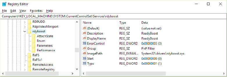
Figure 12-8 ReadyBoost driver service settings.
Reads in the NLS (National Language System) files used for internationalization. By default, these are l_intl.nls, C_1252.nls, and C_437.nls.
If the evaluated policies require the startup of the VSM, executes phase 0 of the Secure Kernel setup, which resolves the locations of the VSM Loader support routines (exported by the Hvloader.dll module), and loads the Secure Kernel module (Securekernel.exe) and all of its dependencies.
For the S edition of Windows, determines the minimum user-mode configurable code integrity signing level for the Windows applications.
Calls the OslArchpKernelSetupPhase0 routine, which performs the memory steps required for kernel transition, like allocating a GDT, IDT, and TSS; mapping the HAL virtual address space; and allocating the kernel stacks, shared user page, and USB legacy handoff. Winload uses the UEFI GetMemoryMap facility to obtain a complete system physical memory map and maps each physical page that belongs to EFI Runtime Code/Data into virtual memory space. The complete physical map will be passed to the OS kernel.
Executes phase 1 of VSM setup, copying all the needed ACPI tables from VTL0 to VTL1 memory. (This step also builds the VTL1 page tables.)
The virtual memory translation module is completely functional, so Winload calls the ExitBootServices UEFI function to get rid of the firmware boot services and remaps all the remaining Runtime UEFI services into the created virtual address space, using the SetVirtualAddressMap UEFI runtime function.
If needed, launches the hypervisor and the Secure Kernel (exactly in this order). If successful, the execution control returns to Winload in the context of the Hyper-V Root Partition. (Refer to Chapter 9, “Virtualization technologies,” for details about Hyper-V.)
Transfers the execution to the kernel through the OslArchTransferToKernel routine.
Booting from iSCSI
Internet SCSI (iSCSI) devices are a kind of network-attached storage in that remote physical disks are connected to an iSCSI Host Bus Adapter (HBA) or through Ethernet. These devices, however, are different from traditional network-attached storage (NAS) because they provide block-level access to disks, unlike the logical-based access over a network file system that NAS employs. Therefore, an iSCSI-connected disk appears as any other disk drive, both to the boot loader and to the OS, as long as the Microsoft iSCSI Initiator is used to provide access over an Ethernet connection. By using iSCSI-enabled disks instead of local storage, companies can save on space, power consumption, and cooling.
Although Windows has traditionally supported booting only from locally connected disks or network booting through PXE, modern versions of Windows are also capable of natively booting from iSCSI devices through a mechanism called iSCSI Boot. As shown in Figure 12-9, the boot loader (Winload.efi) detects whether the system supports iSCSI boot devices reading the iSCSI Boot Firmware Table (iBFT) that must be present in physical memory (typically exposed through ACPI). Thanks to the iBFT table, Winload knows the location, path, and authentication information for the remote disk. If the table is present, Winload opens and loads the network interface driver provided by the manufacturer, which is marked with the CM_SERVICE_NETWORK_BOOT_LOAD (0x1) boot flag.
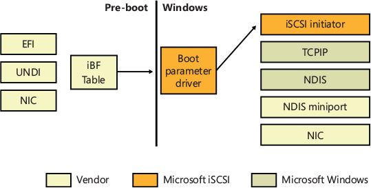
Figure 12-9 iSCSI boot architecture.
Additionally, Windows Setup also has the capability of reading this table to determine bootable iSCSI devices and allow direct installation on such a device, such that no imaging is required. In combination with the Microsoft iSCSI Initiator, this is all that’s required for Windows to boot from iSCSI.
The hypervisor loader
The hypervisor loader is the boot module (its file name is Hvloader.dll) used to properly load and start the Hyper-V hypervisor and the Secure Kernel. For a complete description of Hyper-V and the Secure Kernal, refer to Chapter 9. The hypervisor loader module is deeply integrated in the Windows Loader and has two main goals:
■ Detect the hardware platform; load and start the proper version of the Windows Hypervisor (Hvix64.exe for Intel Systems, Hvax64.exe for AMD systems and Hvaa64.exe for ARM64 systems).
■ Parse the Virtual Secure Mode (VSM) policy; load and start the Secure Kernel.
In Windows 8, this module was an external executable loaded by Winload on demand. At that time the only duty of the hypervisor loader was to load and start Hyper-V. With the introduction of the VSM and Trusted Boot, the architecture has been redesigned for a better integration of each component.
As previously mentioned, the hypervisor setup has two different phases. The first phase begins in Winload, just after the initialization of the NT Loader Block. The HvLoader detects the target platform through some CPUID instructions, copies the UEFI physical memory map, and discovers the IOAPICs and IOMMUs. Then HvLoader loads the correct hypervisor image (and all the dependencies, like the Debugger transport) in memory and checks whether the hypervisor version information matches the one expected. (This explains why the HvLoader couldn’t start a different version of Hyper-V.) HvLoader at this stage allocates the hypervisor loader block, an important data structure used for passing system parameters between HvLoader and the hypervisor itself (similar to the Windows loader block). The most important step of phase 1 is the construction of the hypervisor page tables hierarchy. The just-born page tables include only the mapping of the hypervisor image (and its dependencies) and the system physical pages below the first megabyte. The latter are identity-mapped and are used by the startup transitional code (this concept is explained later in this section).
The second phase is initiated in the final stages of Winload: the UEFI firmware boot services have been discarded, so the HvLoader code copies the physical address ranges of the UEFI Runtime Services into the hypervisor loader block; captures the processor state; disables the interrupts, the debugger, and paging; and calls HvlpTransferToHypervisorViaTransitionSpace to transfer the code execution to the below 1 MB physical page. The code located here (the transitional code) can switch the page tables, re-enable paging, and move to the hypervisor code (which actually creates the two different address spaces). After the hypervisor starts, it uses the saved processor context to properly yield back the code execution to Winload in the context of a new virtual machine, called root partition (more details available in Chapter 9).
The launch of the virtual secure mode is divided in three different phases because some steps are required to be done after the hypervisor has started.
The first phase is very similar to the first phase in the hypervisor setup. Data is copied from the Windows loader block to the just-allocated VSM loader block; the master key, IDK key, and Crashdump key are generated; and the SecureKernel.exe module is loaded into memory.
The second phase is initiated by Winload in the late stages of OslPrepareTarget, where the hypervisor has been already initialized but not launched. Similar to the second phase of the hypervisor setup, the UEFI runtime services physical address ranges are copied into the VSM loader block, along with ACPI tables, code integrity data, the complete system physical memory map, and the hypercall code page. Finally, the second phase constructs the protected page tables hierarchy used for the protected VTL1 memory space (using the OslpVsmBuildPageTables function) and builds the needed GDT.
The third phase is the final “launch” phase. The hypervisor has already been launched. The third phase performs the final checks. (Checks such as whether an IOMMU is present, and whether the root partition has VSM privileges. The IOMMU is very important for VSM. Refer to Chapter 9 for more information.) This phase also sets the encrypted hypervisor crash dump area, copies the VSM encryption keys, and transfers execution to the Secure Kernel entry point (SkiSystemStartup). The Secure Kernel entry point code runs in VTL 0. VTL 1 is started by the Secure Kernel code in later stages through the HvCallEnablePartitionVtl hypercall. (Read Chapter 9 for more details.)
VSM startup policy
At startup time, the Windows loader needs to determine whether it has to launch the Virtual Secure Mode (VSM). To defeat all the malware attempts to disable this new layer of protection, the system uses a specific policy to seal the VSM startup settings. In the default configurations, at the first boot (after the Windows Setup application has finished to copy the Windows files), the Windows Loader uses the OslSetVsmPolicy routine to read and seal the VSM configuration, which is stored in the VSM root registry key HKLMSYSTEMCurrentControlSetControlDeviceGuard.
VSM can be enabled by different sources:
■ Device Guard Scenarios Each scenario is stored as a subkey in the VSM root key. The Enabled DWORD registry value controls whether a scenario is enabled. If one or more scenarios are active, the VSM is enabled.
■ Global Settings Stored in the EnableVirtualizationBasedSecurity registry value.
■ HVCI Code Integrity policies Stored in the code integrity policy file (Policy.p7b).
Also, by default, VSM is automatically enabled when the hypervisor is enabled (except if the HyperVVirtualizationBasedSecurityOptOut registry value exists).
Every VSM activation source specifies a locking policy. If the locking mode is enabled, the Windows loader builds a Secure Boot variable, called VbsPolicy, and stores in it the VSM activation mode and the platform configuration. Part of the VSM platform configuration is dynamically generated based on the detected system hardware, whereas another part is read from the RequirePlatformSecurityFeatures registry value stored in the VSM root key. The Secure Boot variable is read at every subsequent boot; the configuration stored in the variable always replaces the configuration located in the Windows registry.
In this way, even if malware can modify the Windows Registry to disable VSM, Windows will simply ignore the change and keep the user environment secure. Malware won’t be able to modify the VSM Secure Boot variable because, per Secure Boot specification, only a new variable signed by a trusted digital signature can modify or delete the original one. Microsoft provides a special signed tool that could disable the VSM protection. The tool is a special EFI boot application, which sets another signed Secure Boot variable called VbsPolicyDisabled. This variable is recognized at startup time by the Windows Loader. If it exists, Winload deletes the VbsPolicy secure variable and modifies the registry to disable VSM (modifying both the global settings and each Scenario activation).


The Secure Launch
If Trusted Execution is enabled (through a specific feature value in the VSM policy) and the system is compatible, Winload enables a new boot path that’s a bit different compared to the normal one. This new boot path is called Secure Launch. Secure Launch implements the Intel Trusted Boot (TXT) technology (or SKINIT in AMD64 machines). Trusted Boot is implemented in two components: boot library and the TcbLaunch.exe file. The Boot library, at initialization time, detects that Trusted Boot is enabled and registers a boot callback that intercepts different events: Boot application starting, hash calculation, and Boot application ending. The Windows loader, in the early stages, executes to the three stages of Secure Launch Setup (from now on we call the Secure Launch setup the TCB setup) instead of loading the hypervisor.
As previously discussed, the final goal of Secure Launch is to start a secure boot sequence, where the CPU is the only root of trust. To do so, the system needs to get rid of all the firmware dependencies. Windows achieves this by creating a RAM disk formatted with the FAT file system, which includes Winload, the hypervisor, the VSM module, and all the boot OS components needed to start the system. The windows loader (Winload) reads TcbLaunch.exe from the system boot disk into memory, using the BlImgLoadBootApplication routine. The latter triggers the three events that the TCB boot callback manages. The callback first prepares the Measured Launch Environment (MLE) for launch, checking the ACM modules, ACPI table, and mapping the required TXT regions; then it replaces the boot application entry point with a special TXT MLE routine.
The Windows Loader, in the latest stages of the OslExecuteTransition routine, doesn’t start the hypervisor launch sequence. Instead, it transfers the execution to the TCB launch sequence, which is quite simple. The TCB boot application is started with the same BlImgStartBootApplication routine described in the previous paragraph. The modified boot application entry point calls the TXT MLE launch routine, which executes the GETSEC(SENTER) TXT instruction. This instruction measures the TcbLaunch.exe executable in memory (TBOOT module) and if the measurement succeeds, the MLE launch routine transfers the code execution to the real boot application entry point (TcbMain).
TcbMain function is the first code executed in the Secure Launch environment. The implementation is simple: reinitialize the Boot Library, register an event to receive virtualization launch/resume notification, and call TcbLoadEntry from the Tcbloader.dll module located in the secure RAM disk. The Tcbloader.dll module is a mini version of the trusted Windows loader. Its goal is to load, verify, and start the hypervisor; set up the Hypercall page; and launch the Secure Kernel. The Secure Launch at this stage ends because the hypervisor and Secure Kernel take care of the verification of the NT kernel and other modules, providing the chain of trust. Execution then returns to the Windows loader, which moves to the Windows kernel through the standard OslArchTransferToKernel routine.
Figure 12-10 shows a scheme of Secure Launch and all its involved components. The user can enable the Secure Launch by using the Local Group policy editor (by tweaking the Turn On Virtualization Based Security setting, which is under Computer Configuration, Administrative Templates, System, Device Guard).

Figure 12-10 The Secure Launch scheme. Note that the hypervisor and Secure Kernel start from the RAM disk.
![]() Note
Note
The ACM modules of Trusted Boot are provided by Intel and are chipset-dependent. Most of the TXT interface is memory mapped in physical memory. This means that the Hv Loader can access even the SINIT region, verify the SINIT ACM version, and update it if needed. Windows achieves this by using a special compressed WIM file (called Tcbres.wim) that contains all the known SINIT ACM modules for each chipset. If needed, the MLE preparation phase opens the compressed file, extracts the right binary module, and replaces the contents of the original SINIT firmware in the TXT region. When the Secure Launch procedure is invoked, the CPU loads the SINIT ACM into secure memory, verifies the integrity of the digital signature, and compares the hash of its public key with the one hardcoded into the chipset.
Secure Launch on AMD platforms
Although Secure Launch is supported on Intel machines thanks to TXT, the Windows 10 Spring 2020 update also supports SKINIT, which is a similar technology designed by AMD for the verifiable startup of trusted software, starting with an initially untrusted operating mode.
SKINIT has the same goal as Intel TXT and is used for the Secure Launch boot flow. It’s different from the latter, though: The base of SKINIT is a small type of software called secure loader (SL), which in Windows is implemented in the amdsl.bin binary included in the resource section of the Amddrtm.dll library provided by AMD. The SKINIT instruction reinitializes the processor to establish a secure execution environment and starts the execution of the SL in a way that can’t be tampered with. The secure loader lives in the Secure Loader Block, a 64-Kbyte structure that is transferred to the TPM by the SKINIT instruction. The TPM measures the integrity of the SL and transfers execution to its entry point.
The SL validates the system state, extends measurements into the PCR, and transfers the execution to the AMD MLE launch routine, which is located in a separate binary included in the TcbLaunch.exe module. The MLE routine initializes the IDT and GDT and builds the page table for switching the processor to long mode. (The MLE in AMD machines are executed in 32-bit protected mode, with a goal of keeping the code in the TCB as small as possible.) It finally jumps back in the TcbLaunch, which, as for Intel systems, reinitializes the Boot Library, registers an event to receive virtualization launch/resume notification, and calls TcbLoadEntry from the tcbloader.dll module. From now on, the boot flow is identical to the Secure Launch implementation for the Intel systems.
Initializing the kernel and executive subsystems
When Winload calls Ntoskrnl, it passes a data structure called the Loader Parameter block. The Loader Parameter block contains the system and boot partition paths, a pointer to the memory tables Winload generated to describe the system physical memory, a physical hardware tree that is later used to build the volatile HARDWARE registry hive, an in-memory copy of the SYSTEM registry hive, and a pointer to the list of boot drivers Winload loaded. It also includes various other information related to the boot processing performed until this point.
Ntoskrnl then begins phase 0, the first of its two-phase initialization process (phase 1 is the second). Most executive subsystems have an initialization function that takes a parameter that identifies which phase is executing.
During phase 0, interrupts are disabled. The purpose of this phase is to build the rudimentary structures required to allow the services needed in phase 1 to be invoked. Ntoskrnl’s startup function, KiSystemStartup, is called in each system processor context (more details later in this chapter in the “Kernel initialization phase 1” section). It initializes the processor boot structures and sets up a Global Descriptor Table (GDT) and Interrupt Descriptor Table (IDT). If called from the boot processor, the startup routine initializes the Control Flow Guard (CFG) check functions and cooperates with the memory manager to initialize KASLR. The KASLR initialization should be done in the early stages of the system startup; in this way, the kernel can assign random VA ranges for the various virtual memory regions (such as the PFN database and system PTE regions; more details about KASLR are available in the “Image randomization” section of Chapter 5, Part 1). KiSystemStartup also initializes the kernel debugger, the XSAVE processor area, and, where needed, KVA Shadow. It then calls KiInitializeKernel. If KiInitializeKernel is running on the boot CPU, it performs systemwide kernel initialization, such as initializing internal lists and other data structures that all CPUs share. It builds and compacts the System Service Descriptor table (SSDT) and calculates the random values for the internal KiWaitAlways and KiWaitNever values, which are used for kernel pointers encoding. It also checks whether virtualization has been started; if it has, it maps the Hypercall page and starts the processor’s enlightenments (more details about the hypervisor enlightenments are available in Chapter 9).
KiInitializeKernel, if executed by compatible processors, has the important role of initializing and enabling the Control Enforcement Technology (CET). This hardware feature is relatively new, and basically implements a hardware shadow stack, used to detect and prevent ROP attacks. The technology is used for protecting both user-mode applications as well as kernel-mode drivers (only when VSM is available). KiInitializeKernel initializes the Idle process and thread and calls ExpInitializeExecutive. KiInitializeKernel and ExpInitializeExecutive are normally executed on each system processor. When executed by the boot processor, ExpInitializeExecutive relies on the function responsible for orchestrating phase 0, InitBootProcessor, while subsequent processors call only InitOtherProcessors.
![]() Note
Note
Return-oriented programming (ROP) is an exploitation technique in which an attacker gains control of the call stack of a program with the goal of hijacking its control flow and executes carefully chosen machine instruction sequences, called “gadgets,” that are already present in the machine’s memory. Chained together, multiple gadgets allow an attacker to perform arbitrary operations on a machine.
InitBootProcessor starts by validating the boot loader. If the boot loader version used to launch Windows doesn’t correspond to the right Windows kernel, the function crashes the system with a LOADER_BLOCK_MISMATCH bugcheck code (0x100). Otherwise, it initializes the pool look-aside pointers for the initial CPU and checks for and honors the BCD burnmemory boot option, where it discards the amount of physical memory the value specifies. It then performs enough initialization of the NLS files that were loaded by Winload (described earlier) to allow Unicode to ANSI and OEM translation to work. Next, it continues by initializing Windows Hardware Error Architecture (WHEA) and calling the HAL function HalInitSystem, which gives the HAL a chance to gain system control before Windows performs significant further initialization. HalInitSystem is responsible for initializing and starting various components of the HAL, like ACPI tables, debugger descriptors, DMA, firmware, I/O MMU, System Timers, CPU topology, performance counters, and the PCI bus. One important duty of HalInitSystem is to prepare each CPU interrupt controller to receive interrupts and to configure the interval clock timer interrupt, which is used for CPU time accounting. (See the section “Quantum” in Chapter 4, “Threads,” in Part 1 for more on CPU time accounting.)
When HalInitSystem exits, InitBootProcessor proceeds by computing the reciprocal for clock timer expiration. Reciprocals are used for optimizing divisions on most modern processors. They can perform multiplications faster, and because Windows must divide the current 64-bit time value in order to find out which timers need to expire, this static calculation reduces interrupt latency when the clock interval fires. InitBootProcessor uses a helper routine, CmInitSystem0, to fetch registry values from the control vector of the SYSTEM hive. This data structure contains more than 150 kernel-tuning options that are part of the HKLMSYSTEMCurrentControlSetControl registry key, including information such as the licensing data and version information for the installation. All the settings are preloaded and stored in global variables. InitBootProcessor then continues by setting up the system root path and searching into the kernel image to find the crash message strings it displays on blue screens, caching their location to avoid looking them up during a crash, which could be dangerous and unreliable. Next, InitBootProcessor initializes the timer subsystem and the shared user data page.
InitBootProcessor is now ready to call the phase 0 initialization routines for the executive, Driver Verifier, and the memory manager. These components perform the following initialization tasks:
The executive initializes various internal locks, resources, lists, and variables and validates that the product suite type in the registry is valid, discouraging casual modification of the registry to “upgrade” to an SKU of Windows that was not actually purchased. This is only one of the many such checks in the kernel.
Driver Verifier, if enabled, initializes various settings and behaviors based on the current state of the system (such as whether safe mode is enabled) and verification options. It also picks which drivers to target for tests that target randomly chosen drivers.
The memory manager constructs the page tables, PFN database, and internal data structures that are necessary to provide basic memory services. It also enforces the limit of the maximum supported amount of physical memory and builds and reserves an area for the system file cache. It then creates memory areas for the paged and nonpaged pools (described in Chapter 5 in Part 1). Other executive subsystems, the kernel, and device drivers use these two memory pools for allocating their data structures. It finally creates the UltraSpace, a 16 TB region that provides support for fast and inexpensive page mapping that doesn’t require TLB flushing.
Next, InitBootProcessor enables the hypervisor CPU dynamic partitioning (if enabled and correctly licensed), and calls HalInitializeBios to set up the old BIOS emulation code part of the HAL. This code is used to allow access (or to emulate access) to 16-bit real mode interrupts and memory, which are used mainly by Bootvid (this driver has been replaced by BGFX but still exists for compatibility reasons).
At this point, InitBootProcessor enumerates the boot-start drivers that were loaded by Winload and calls DbgLoadImageSymbols to inform the kernel debugger (if attached) to load symbols for each of these drivers. If the host debugger has configured the break on symbol load option, this will be the earliest point for a kernel debugger to gain control of the system. InitBootProcessor now calls HvlPhase1Initialize, which performs the remaining HVL initialization that hasn’t been possible to complete in previous phases. When the function returns, it calls HeadlessInit to initialize the serial console if the machine was configured for Emergency Management Services (EMS).
Next, InitBootProcessor builds the versioning information that will be used later in the boot process, such as the build number, service pack version, and beta version status. Then it copies the NLS tables that Winload previously loaded into the paged pool, reinitializes them, and creates the kernel stack trace database if the global flags specify creating one. (For more information on the global flags, see Chapter 6, “I/O system,” in Part 1.)
Finally, InitBootProcessor calls the object manager, security reference monitor, process manager, user-mode debugging framework, and Plug and Play manager. These components perform the following initialization steps:
During the object manager initialization, the objects that are necessary to construct the object manager namespace are defined so that other subsystems can insert objects into it. The system process and the global kernel handle tables are created so that resource tracking can begin. The value used to encrypt the object header is calculated, and the Directory and SymbolicLink object types are created.
The security reference monitor initializes security global variables (like the system SIDs and Privilege LUIDs) and the in-memory database, and it creates the token type object. It then creates and prepares the first local system account token for assignment to the initial process. (See Chapter 7 in Part 1 for a description of the local system account.)
The process manager performs most of its initialization in phase 0, defining the process, thread, job, and partition object types and setting up lists to track active processes and threads. The systemwide process mitigation options are initialized and merged with the options specified in the HKLMSYSTEMCurrentControlSetControlSession ManagerKernelMitigationOptions registry value. The process manager then creates the executive system partition object, which is called MemoryPartition0. The name is a little misleading because the object is actually an executive partition object, a new Windows object type that encapsulates a memory partition and a cache manager partition (for supporting the new application containers).
The process manager also creates a process object for the initial process and names it idle. As its last step, the process manager creates the System protected process and a system thread to execute the routine Phase1Initialization. This thread doesn’t start running right away because interrupts are still disabled. The System process is created as protected to get protection from user mode attacks, because its virtual address space is used to map sensitive data used by the system and by the Code Integrity driver. Furthermore, kernel handles are maintained in the system process’s handle table.
The user-mode debugging framework creates the definition of the debug object type that is used for attaching a debugger to a process and receiving debugger events. For more information on user-mode debugging, see Chapter 8, “System mechanisms.”
The Plug and Play manager’s phase 0 initialization then takes place, which involves initializing an executive resource used to synchronize access to bus resources.
When control returns to KiInitializeKernel, the last step is to allocate the DPC stack for the current processor, raise the IRQL to dispatch level, and enable the interrupts. Then control proceeds to the Idle loop, which causes the system thread created in step 4 to begin executing phase 1. (Secondary processors wait to begin their initialization until step 11 of phase 1, which is described in the following list.)
Kernel initialization phase 1
As soon as the Idle thread has a chance to execute, phase 1 of kernel initialization begins. Phase 1 consists of the following steps:
Phase1InitializationDiscard, as the name implies, discards the code that is part of the INIT section of the kernel image in order to preserve memory.
The initialization thread sets its priority to 31, the highest possible, to prevent preemption.
The BCD option that specifies the maximum number of virtual processors (hypervisorrootproc) is evaluated.
The NUMA/group topology relationships are created, in which the system tries to come up with the most optimized mapping between logical processors and processor groups, taking into account NUMA localities and distances, unless overridden by the relevant BCD settings.
HalInitSystem performs phase 1 of its initialization. It prepares the system to accept interrupts from external peripherals.
The system clock interrupt is initialized, and the system clock tick generation is enabled.
The old boot video driver (bootvid) is initialized. It’s used only for printing debug messages and messages generated by native applications launched by SMSS, such as the NT chkdsk.
The kernel builds various strings and version information, which are displayed on the boot screen through Bootvid if the sos boot option was enabled. This includes the full version information, number of processors supported, and amount of memory supported.
The power manager’s initialization is called.
The system time is initialized (by calling HalQueryRealTimeClock) and then stored as the time the system booted.
On a multiprocessor system, the remaining processors are initialized by KeStartAllProcessors and HalAllProcessorsStarted. The number of processors that will be initialized and supported depends on a combination of the actual physical count, the licensing information for the installed SKU of Windows, boot options such as numproc and bootproc, and whether dynamic partitioning is enabled (server systems only). After all the available processors have initialized, the affinity of the system process is updated to include all processors.
The object manager initializes the global system silo, the per-processor nonpaged lookaside lists and descriptors, and base auditing (if enabled by the system control vector). It then creates the namespace root directory (), KernelObjects directory, ObjectTypes directory, and the DOS device name mapping directory (Global??), with the Global and GLOBALROOT links created in it. The object manager then creates the silo device map that will control the DOS device name mapping and attach it to the system process. It creates the old DosDevices symbolic link (maintained for compatibility reasons) that points to the Windows subsystem device name mapping directory. The object manager finally inserts each registered object type in the ObjectTypes directory object.
The executive is called to create the executive object types, including semaphore, mutex, event, timer, keyed event, push lock, and thread pool worker.
The I/O manager is called to create the I/O manager object types, including device, driver, controller, adapter, I/O completion, wait completion, and file objects.
The kernel initializes the system watchdogs. There are two main types of watchdog: the DPC watchdog, which checks that a DPC routine will not execute more than a specified amount of time, and the CPU Keep Alive watchdog, which verifies that each CPU is always responsive. The watchdogs aren’t initialized if the system is executed by a hypervisor.
The kernel initializes each CPU processor control block (KPRCB) data structure, calculates the Numa cost array, and finally calculates the System Tick and Quantum duration.
The kernel debugger library finalizes the initialization of debugging settings and parameters, regardless of whether the debugger has not been triggered prior to this point.
The transaction manager also creates its object types, such as the enlistment, resource manager, and transaction manager types.
The user-mode debugging library (Dbgk) data structures are initialized for the global system silo.
If driver verifier is enabled and, depending on verification options, pool verification is enabled, object handle tracing is started for the system process.
The security reference monitor creates the Security directory in the object manager namespace, protecting it with a security descriptor in which only the SYSTEM account has full access, and initializes auditing data structures if auditing is enabled. Furthermore, the security reference monitor initializes the kernel-mode SDDL library and creates the event that will be signaled after the LSA has initialized (SecurityLSA_AUTHENTICATION_INITIALIZED).
Finally, the Security Reference Monitor initializes the Kernel Code Integrity component (Ci.dll) for the first time by calling the internal CiInitialize routine, which initializes all the Code Integrity Callbacks and saves the list of boot drivers for further auditing and verification.
The process manager creates a system handle for the executive system partition. The handle will never be dereferenced, so as a result the system partition cannot be destroyed. The Process Manager then initializes the support for kernel optional extension (more details are in step 26). It registers host callouts for various OS services, like the Background Activity Moderator (BAM), Desktop Activity Moderator (DAM), Multimedia Class Scheduler Service (MMCSS), Kernel Hardware Tracing, and Windows Defender System Guard.
Finally, if VSM is enabled, it creates the first minimal process, the IUM System Process, and assigns it the name Secure System.
The SystemRoot symbolic link is created.
The memory manager is called to perform phase 1 of its initialization. This phase creates the Section object type, initializes all its associated data structures (like the control area), and creates the DevicePhysicalMemory section object. It then initializes the kernel Control Flow Guard support and creates the pagefile-backed sections that will be used to describe the user mode CFG bitmap(s). (Read more about Control Flow Guard in Chapter 7, Part 1.) The memory manager initializes the Memory Enclave support (for SGX compatible systems), the hot-patch support, the page-combining data structures, and the system memory events. Finally, it spawns three memory manager system worker threads (Balance Set Manager, Process Swapper, and Zero Page Thread, which are explained in Chapter 5 of Part 1) and creates a section object used to map the API Set schema memory buffer in the system space (which has been previously allocated by the Windows Loader). The just-created system threads have the chance to execute later, at the end of phase 1.
NLS tables are mapped into system space so that they can be mapped easily by user-mode processes.
The cache manager initializes the file system cache data structures and creates its worker threads.
The configuration manager creates the Registry key object in the object manager namespace and opens the in-memory SYSTEM hive as a proper hive file. It then copies the initial hardware tree data passed by Winload into the volatile HARDWARE hive.
The system initializes Kernel Optional Extensions. This functionality has been introduced in Windows 8.1 with the goal of exporting private system components and Windows loader data (like memory caching requirements, UEFI runtime services pointers, UEFI memory map, SMBIOS data, secure boot policies, and Code Integrity data) to different kernel components (like the Secure Kernel) without using the standard PE (portable executable) exports.
The errata manager initializes and scans the registry for errata information, as well as the INF (driver installation file, described in Chapter 6 of Part 1) database containing errata for various drivers.
The manufacturing-related settings are processed. The manufacturing mode is a special operating system mode that can be used for manufacturing-related tasks, such as components and support testing. This feature is used especially in mobile systems and is provided by the UEFI subsystem. If the firmware indicates to the OS (through a specific UEFI protocol) that this special mode is enabled, Windows reads and writes all the needed information from the HKLMSystemCurrentControlSetControlManufacturingMode registry key.
Superfetch and the prefetcher are initialized.
The Kernel Virtual Store Manager is initialized. The component is part of memory compression.
The VM Component is initialized. This component is a kernel optional extension used to communicate with the hypervisor.
The current time zone information is initialized and set.
Global file system driver data structures are initialized.
The NT Rtl compression engine is initialized.
The support for the hypervisor debugger, if needed, is set up, so that the rest of the system does not use its own device.
Phase 1 of debugger-transport-specific information is performed by calling the KdDebuggerInitialize1 routine in the registered transport, such as Kdcom.dll.
The advanced local procedure call (ALPC) subsystem initializes the ALPC port type and ALPC waitable port type objects. The older LPC objects are set as aliases.
If the system was booted with boot logging (with the BCD bootlog option), the boot log file is initialized. If the system was booted in safe mode, it finds out if an alternate shell must be launched (as in the case of a safe mode with command prompt boot).
The executive is called to execute its second initialization phase, where it configures part of the Windows licensing functionality in the kernel, such as validating the registry settings that hold license data. Also, if persistent data from boot applications is present (such as memory diagnostic results or resume from hibernation information), the relevant log files and information are written to disk or to the registry.
The MiniNT/WinPE registry keys are created if this is such a boot, and the NLS object directory is created in the namespace, which will be used later to host the section objects for the various memory-mapped NLS files.
The Windows kernel Code Integrity policies (like the list of trusted signers and certificate hashes) and debugging options are initialized, and all the related settings are copied from the Loader Block to the kernel CI module (Ci.dll).
The power manager is called to initialize again. This time it sets up support for power requests, the power watchdogs, the ALPC channel for brightness notifications, and profile callback support.
The I/O manager initialization now takes place. This stage is a complex phase of system startup that accounts for most of the boot time.
The I/O manager first initializes various internal structures and creates the driver and device object types as well as its root directories: Driver, FileSystem, FileSystemFilters, and UMDFCommunicationPorts (for the UMDF driver framework). It then initializes the Kernel Shim Engine, and calls the Plug and Play manager, power manager, and HAL to begin the various stages of dynamic device enumeration and initialization. (We covered all the details of this complex and specific process in Chapter 6 of Part 1.) Then the Windows Management Instrumentation (WMI) subsystem is initialized, which provides WMI support for device drivers. (See the section “Windows Management Instrumentation” in Chapter 10 for more information.) This also initializes Event Tracing for Windows (ETW) and writes all the boot persistent data ETW events, if any.
The I/O manager starts the platform-specific error driver and initializes the global table of hardware error sources. These two are vital components of the Windows Hardware Error infrastructure. Then it performs the first Secure Kernel call, asking the Secure Kernel to perform the last stage of its initialization in VTL 1. Also, the encrypted secure dump driver is initialized, reading part of its configuration from the Windows Registry (HKLMSystemCurrentControlSetControlCrashControl).
All the boot-start drivers are enumerated and ordered while respecting their dependencies and load-ordering. (Details on the processing of the driver load control information on the registry are also covered in Chapter 6 of Part 1.) All the linked kernel mode DLLs are initialized with the built-in RAW file system driver.
At this stage, the I/O manager maps Ntdll.dll, Vertdll.dll, and the WOW64 version of Ntdll into the system address space. Finally, all the boot-start drivers are called to perform their driver-specific initialization, and then the system-start device drivers are started. The Windows subsystem device names are created as symbolic links in the object manager’s namespace.
The configuration manager registers and starts its Windows registry’s ETW Trace Logging Provider. This allows the tracing of the entire configuration manager.
The transaction manager sets up the Windows software trace preprocessor (WPP) and registers its ETW Provider.
Now that boot-start and system-start drivers are loaded, the errata manager loads the INF database with the driver errata and begins parsing it, which includes applying registry PCI configuration workarounds.
If the computer is booting in safe mode, this fact is recorded in the registry.
Unless explicitly disabled in the registry, paging of kernel-mode code (in Ntoskrnl and drivers) is enabled.
The power manager is called to finalize its initialization.
The kernel clock timer support is initialized.
Before the INIT section of Ntoskrnl will be discarded, the rest of the licensing information for the system is copied into a private system section, including the current policy settings that are stored in the registry. The system expiration time is then set.
The process manager is called to set up rate limiting for jobs and the system process creation time. It initializes the static environment for protected processes, and looks up various system-defined entry points in the user-mode system libraries previously mapped by the I/O manager (usually Ntdll.dll, Ntdll32.dll, and Vertdll.dll).
The security reference monitor is called to create the Command Server thread that communicates with LSASS. This phase creates the Reference Monitor command port, used by LSA to send commands to the SRM. (See the section “Security system components” in Chapter 7 in Part 1 for more on how security is enforced in Windows.)
If the VSM is enabled, the encrypted VSM keys are saved to disk. The system user-mode libraries are mapped into the Secure System Process. In this way, the Secure Kernel receives all the needed information about the VTL 0’s system DLLs.
The Session Manager (Smss) process (introduced in Chapter 2, “System architecture,” in Part 1) is started. Smss is responsible for creating the user-mode environment that provides the visible interface to Windows—its initialization steps are covered in the next section.
The bootvid driver is enabled to allow the NT check disk tool to display the output strings.
The TPM boot entropy values are queried. These values can be queried only once per boot, and normally, the TPM system driver should have queried them by now, but if this driver has not been running for some reason (perhaps the user disabled it), the unqueried values would still be available. Therefore, the kernel also manually queries them to avoid this situation; in normal scenarios, the kernel’s own query should fail.
All the memory used by the loader parameter block and all its references (like the initialization code of Ntoskrnl and all boot drivers, which reside in the INIT sections) are now freed.
As a final step before considering the executive and kernel initialization complete, the phase 1 initialization thread sets the critical break on termination flag to the new Smss process. In this way, if the Smss process exits or gets terminated for some reason, the kernel intercepts this, breaks into the attached debugger (if any), and crashes the system with a CRITICAL_PROCESS_DIED stop code.
If the five-second wait times out (that is, if five seconds elapse), the Session Manager is assumed to have started successfully, and the phase 1 initialization thread exits. Thus, the boot processor executes one of the memory manager’s system threads created in step 22 or returns to the Idle loop.
Smss, Csrss, and Wininit
Smss is like any other user-mode process except for two differences. First, Windows considers Smss a trusted part of the operating system. Second, Smss is a native application. Because it’s a trusted operating system component, Smss runs as a protected process light (PPL; PPLs are covered in Part 1, Chapter 3, “Processes and jobs”) and can perform actions few other processes can perform, such as creating security tokens. Because it’s a native application, Smss doesn’t use Windows APIs—it uses only core executive APIs known collectively as the Windows native API (which are normally exposed by Ntdll). Smss doesn’t use the Win32 APIs, because the Windows subsystem isn’t executing when Smss launches. In fact, one of Smss’s first tasks is to start the Windows subsystem.
Smss initialization has been already covered in the “Session Manager” section of Chapter 2 of Part 1. For all the initialization details, please refer to that chapter. When the master Smss creates the children Smss processes, it passes two section objects’ handles as parameters. The two section objects represent the shared buffers used for exchanging data between multiple Smss and Csrss instances (one is used to communicate between the parent and the child Smss processes, and the other is used to communicate with the client subsystem process). The master Smss spawns the child using the RtlCreateUserProcess routine, specifying a flag to instruct the Process Manager to create a new session. In this case, the PspAllocateProcess kernel function calls the memory manager to create the new session address space.
The executable name that the child Smss launches at the end of its initialization is stored in the shared section, and, as stated in Chapter 2, is usually Wininit.exe for session 0 and Winlogon.exe for any interactive sessions. An important concept to remember is that before the new session 0 Smss launches Wininit, it connects to the Master Smss (through the SmApiPort ALPC port) and loads and initializes all the subsystems.
The session manager acquires the Load Driver privilege and asks the kernel to load and map the Win32k driver into the new Session address space (using the NtSetSystemInformation native API). It then launches the client-server subsystem process (Csrss.exe), specifying in the command line the following information: the root Windows Object directory name (Windows), the shared section objects’ handles, the subsystem name (Windows), and the subsystem’s DLLs:
■ Basesrv.dll The server side of the subsystem process
■ Sxssrv.dll The side-by-side subsystem support extension module
■ Winsrv.dll The multiuser subsystem support module
The client–server subsystem process performs some initialization: It enables some process mitigation options, removes unneeded privileges from its token, starts its own ETW provider, and initializes a linked list of CSR_PROCESS data structures to trace all the Win32 processes that will be started in the system. It then parses its command line, grabs the shared sections’ handles, and creates two ALPC ports:
■ CSR API command port (Sessions<ID>WindowsApiPort) This ALPC Port will be used by every Win32 process to communicate with the Csrss subsystem. (Kernelbase.dll connects to it in its initialization routine.)
■ Subsystem Session Manager API Port (Sessions<ID>WindowsSbApiPort) This port is used by the session manager to send commands to Csrss.
Csrss creates the two threads used to dispatch the commands received by the ALPC ports. Finally, it connects to the Session Manager, through another ALPC port (SmApiPort), which was previously created in the Smss initialization process (step 6 of the initialization procedure described in Chapter 2). In the connection process, the Csrss process sends the name of the just-created Session Manager API port. From now on, new interactive sessions can be started. So, the main Csrss thread finally exits.
After spawning the subsystem process, the child Smss launches the initial process (Wininit or Winlogon) and then exits. Only the master instance of Smss remains active. The main thread in Smss waits forever on the process handle of Csrss, whereas the other ALPC threads wait for messages to create new sessions or subsystems. If either Wininit or Csrss terminate unexpectedly, the kernel crashes the system because these processes are marked as critical. If Winlogon terminates unexpectedly, the session associated with it is logged off.
Wininit performs its startup steps, as described in the “Windows initialization process” section of Chapter 2 in Part 1, such as creating the initial window station and desktop objects. It also sets up the user environment, starts the Shutdown RPC server and WSI interface (see the “Shutdown” section later in this chapter for further details), and creates the service control manager (SCM) process (Services.exe), which loads all services and device drivers marked for auto-start. The local session manager (Lsm.dll) service, which runs in a shared Svchost process, is launched at this time. Wininit next checks whether there has been a previous system crash, and, if so, it carves the crash dump and starts the Windows Error Reporting process (werfault.exe) for further processing. It finally starts the Local Security Authentication Subsystem Service (%SystemRoot%System32Lsass.exe) and, if Credential Guard is enabled, the Isolated LSA Trustlet (Lsaiso.exe) and waits forever for a system shutdown request.
On session 1 and beyond, Winlogon runs instead. While Wininit creates the noninteractive session 0 windows station, Winlogon creates the default interactive-session Windows station, called WinSta0, and two desktops: the Winlogon secure desktop and the default user desktop. Winlogon then queries the system boot information using the NtQuerySystemInformation API (only on the first interactive logon session). If the boot configuration includes the volatile Os Selection menu flag, it starts the GDI system (spawning a UMDF host process, fontdrvhost.exe) and launches the modern boot menu application (Bootim.exe). The volatile Os Selection menu flag is set in early boot stages by the Bootmgr only if a multiboot environment was previously detected (for more details see the section “The boot menu” earlier in this chapter).
Bootim is the GUI application that draws the modern boot menu. The new modern boot uses the Win32 subsystem (graphics driver and GDI+ calls) with the goal of supporting high resolutions for displaying boot choices and advanced options. Even touchscreens are supported, so the user can select which operating system to launch using a simple touch. Winlogon spawns the new Bootim process and waits for its termination. When the user makes a selection, Bootim exits. Winlogon checks the exit code; thus it’s able to detect whether the user has selected an OS or a boot tool or has simply requested a system shutdown. If the user has selected an OS different from the current one, Bootim adds the bootsequence one-shot BCD option in the main system boot store (see the section “The Windows Boot Manager” earlier in this chapter for more details about the BCD store). The new boot sequence is recognized (and the BCD option deleted) by the Windows Boot Manager after Winlogon has restarted the machine using NtShutdownSystem API. Winlogon marks the previous boot entry as good before restarting the system.
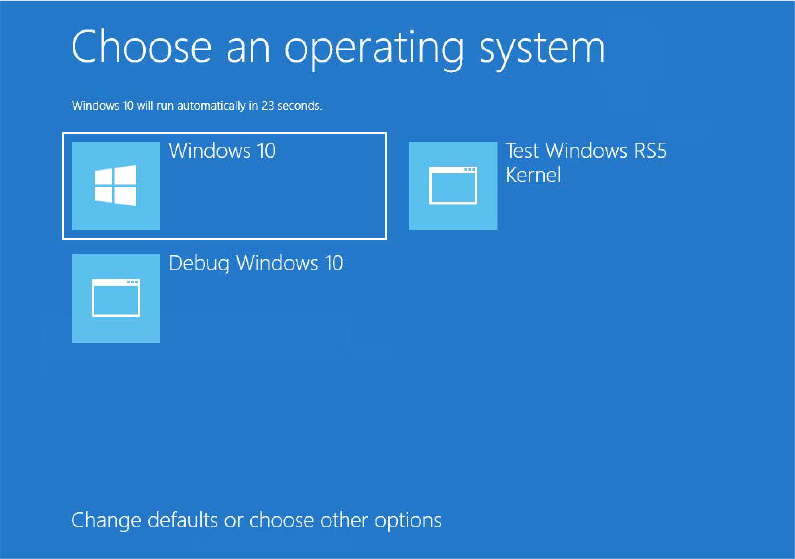
In all other cases, Winlogon waits for the initialization of the LSASS process and LSM service. It then spawns a new instance of the DWM process (Desktop Windows Manager, a component used to draw the modern graphical interface) and loads the registered credential providers for the system (by default, the Microsoft credential provider supports password-based, pin-based, and biometrics-based logons) into a child process called LogonUI (%SystemRoot%System32Logonui.exe), which is responsible for displaying the logon interface. (For more details on the startup sequence for Wininit, Winlogon, and LSASS, see the section “Winlogon initialization” in Chapter 7 in Part 1.)
After launching the LogonUI process, Winlogon starts its internal finite-state machine. This is used to manage all the possible states generated by the different logon types, like the standard interactive logon, terminal server, fast user switch, and hiberboot. In standard interactive logon types, Winlogon shows a welcome screen and waits for an interactive logon notification from the credential provider (configuring the SAS sequence if needed). When the user has inserted their credential (that can be a password, PIN, or biometric information), Winlogon creates a logon session LUID, and validates the logon using the authentication packages registered in Lsass (a process for which you can find more information in the section “User logon steps” in Chapter 7 in Part 1). Even if the authentication won’t succeed, Winlogon at this stage marks the current boot as good. If the authentication succeeded, Winlogon verifies the “sequential logon” scenario in case of client SKUs, in which only one session each time could be generated, and, if this is not the case and another session is active, asks the user how to proceed. It then loads the registry hive from the profile of the user logging on, mapping it to HKCU. It adds the required ACLs to the new session’s Windows Station and Desktop and creates the user’s environment variables that are stored in HKCUEnvironment.
Winlogon next waits the Sihost process and starts the shell by launching the executable or executables specified in HKLMSOFTWAREMicrosoftWindows NTCurrentVersionWinLogonUserinit (with multiple executables separated by commas) that by default points at WindowsSystem32Userinit.exe. The new Userinit process will live in Winsta0Default desktop. Userinit.exe performs the following steps:
Creates the per-session volatile Explorer Session key HKCUSoftwareMicrosoftWindowsCurrentVersionExplorerSessionInfo.
Processes the user scripts specified in HKCUSoftwarePoliciesMicrosoftWindowsSystemScripts and the machine logon scripts in HKLMSOFTWAREPoliciesMicrosoftWindowsSystemScripts. (Because machine scripts run after user scripts, they can override user settings.)
Launches the comma-separated shell or shells specified in HKCUSoftwareMicrosoftWindows NTCurrentVersionWinlogonShell. If that value doesn’t exist, Userinit.exe launches the shell or shells specified in HKLMSOFTWAREMicrosoftWindows NTCurrentVersionWinlogonShell, which is by default Explorer.exe.
If Group Policy specifies a user profile quota, starts %SystemRoot%System32Proquota.exe to enforce the quota for the current user.
Winlogon then notifies registered network providers that a user has logged on, starting the mpnotify.exe process. The Microsoft network provider, Multiple Provider Router (%SystemRoot%System32Mpr.dll), restores the user’s persistent drive letter and printer mappings stored in HKCUNetwork and HKCUPrinters, respectively. Figure 12-11 shows the process tree as seen in Process Monitor after a logon (using its boot logging capability). Note the Smss processes that are dimmed (meaning that they have since exited). These refer to the spawned copies that initialize each session.

Figure 12-11 Process tree during logon.
ReadyBoot
Windows uses the standard logical boot-time prefetcher (described in Chapter 5 of Part 1) if the system has less than 400 MB of free memory, but if the system has 400 MB or more of free RAM, it uses an in-RAM cache to optimize the boot process. The size of the cache depends on the total RAM available, but it’s large enough to create a reasonable cache and yet allow the system the memory it needs to boot smoothly. ReadyBoot is implemented in two distinct binaries: the ReadyBoost driver (Rdyboost.sys) and the Sysmain service (Sysmain.dll, which also implements SuperFetch).
The cache is implemented by the Store Manager in the same device driver that implements ReadyBoost caching (Rdyboost.sys), but the cache’s population is guided by the boot plan previously stored in the registry. Although the boot cache could be compressed like the ReadyBoost cache, another difference between ReadyBoost and ReadyBoot cache management is that while in ReadyBoot mode, the cache is not encrypted. The ReadyBoost service deletes the cache 50 seconds after the service starts, or if other memory demands warrant it.
When the system boots, at phase 1 of the NT kernel initialization, the ReadyBoost driver, which is a volume filter driver, intercepts the boot volume creation and decides whether to enable the cache. The cache is enabled only if the target volume is registered in the HKLMSystemCurrentControlSetServices dyboostParametersReadyBootVolumeUniqueId registry value. This value contains the ID of the boot volume. If ReadyBoot is enabled, the ReadyBoost driver starts to log all the volume boot I/Os (through ETW), and, if a previous boot plan is registered in the BootPlan registry binary value, it spawns a system thread that will populate the entire cache using asynchronous volume reads. When a new Windows OS is installed, at the first system boot these two registry values do not exist, so neither the cache nor the log trace are enabled.
In this situation the Sysmain service, which is started later in the boot process by the SCM, determines whether the cache needs to be enabled, checking the system configuration and the running Windows SKU. There are situations in which ReadyBoot is completely disabled, such as when the boot disk is a solid state drive. If the check yields a positive result, Sysmain enables ReadyBoot by writing the boot volume ID on the relative registry value (ReadyBootVolumeUniqueId) and by enabling the WMI ReadyBoot Autologger in the HKLMSYSTEMCurrentControlSetControlWMIAutoLoggerReadyboot registry key. At the next system boot, the ReadyBoost driver logs all the Volume I/Os but without populating the cache (still no boot plan exists).
After every successive boot, the Sysmain service uses idle CPU time to calculate a boot-time caching plan for the next boot. It analyzes the recorded ETW I/O events and identifies which files were accessed and where they’re located on disk. It then stores the processed traces in %SystemRoot%PrefetchReadyboot as .fx files and calculates the new caching boot plan using the trace files of the five previous boots. The Sysmain service stores the new generated plan under the registry value, as shown in Figure 12-12. The ReadyBoost boot driver reads the boot plan and populates the cache, minimizing the overall boot startup time.

Figure 12-12 ReadyBoot configuration and statistics.
Images that start automatically
In addition to the Userinit and Shell registry values in Winlogon’s key, there are many other registry locations and directories that default system components check and process for automatic process startup during the boot and logon processes. The Msconfig utility (%SystemRoot%System32Msconfig.exe) displays the images configured by several of the locations. The Autoruns tool, which you can download from Sysinternals and is shown in Figure 12-13, examines more locations than Msconfig and displays more information about the images configured to automatically run. By default, Autoruns shows only the locations that are configured to automatically execute at least one image, but selecting the Include Empty Locations entry on the Options menu causes Autoruns to show all the locations it inspects. The Options menu also has selections to direct Autoruns to hide Microsoft entries, but you should always combine this option with Verify Image Signatures; otherwise, you risk hiding malicious programs that include false information about their company name information.

Figure 12-13 The Autoruns tool available from Sysinternals.
Shutdown
The system shutdown process involves different components. Wininit, after having performed all its initialization, waits for a system shutdown.
If someone is logged on and a process initiates a shutdown by calling the Windows ExitWindowsEx function, a message is sent to that session’s Csrss instructing it to perform the shutdown. Csrss in turn impersonates the caller and sends an RPC message to Winlogon, telling it to perform a system shutdown. Winlogon checks whether the system is in the middle of a hybrid boot transition (for further details about hybrid boot, see the “Hybernation and Fast Startup” section later in this chapter), then impersonates the currently logged-on user (who might or might not have the same security context as the user who initiated the system shutdown), asks LogonUI to fade out the screen (configurable through the registry value HKLMSoftwareMicrosoftWindows NCurrentVersionWinlogonFadePeriodConfiguration), and calls ExitWindowsEx with special internal flags. Again, this call causes a message to be sent to the Csrss process inside that session, requesting a system shutdown.
This time, Csrss sees that the request is from Winlogon and loops through all the processes in the logon session of the interactive user (again, not the user who requested a shutdown) in reverse order of their shutdown level. A process can specify a shutdown level, which indicates to the system when it wants to exit with respect to other processes, by calling SetProcessShutdownParameters. Valid shutdown levels are in the range 0 through 1023, and the default level is 640. Explorer, for example, sets its shutdown level to 2, and Task Manager specifies 1. For each active process that owns a top-level window, Csrss sends the WM_QUERYENDSESSION message to each thread in the process that has a Windows message loop. If the thread returns TRUE, the system shutdown can proceed. Csrss then sends the WM_ENDSESSION Windows message to the thread to request it to exit. Csrss waits the number of seconds defined in HKCUControl PanelDesktopHungAppTimeout for the thread to exit. (The default is 5000 milliseconds.)
If the thread doesn’t exit before the timeout, Csrss fades out the screen and displays the hung-program screen shown in Figure 12-14. (You can disable this screen by creating the registry value HKCUControl PanelDesktopAutoEndTasks and setting it to 1.) This screen indicates which programs are currently running and, if available, their current state. Windows indicates which program isn’t shutting down in a timely manner and gives the user a choice of either killing the process or aborting the shutdown. (There is no timeout on this screen, which means that a shutdown request could wait forever at this point.) Additionally, third-party applications can add their own specific information regarding state—for example, a virtualization product could display the number of actively running virtual machines (using the ShutdownBlockReasonCreate API).

Figure 12-14 Hung-program screen.

If the thread does exit before the timeout, Csrss continues sending the WM_QUERYENDSESSION/WM_ENDSESSION message pairs to the other threads in the process that own windows. Once all the threads that own windows in the process have exited, Csrss terminates the process and goes on to the next process in the interactive session.
If Csrss finds a console application, it invokes the console control handler by sending the CTRL_LOGOFF_EVENT event. (Only service processes receive the CTRL_SHUTDOWN_EVENT event on shutdown.) If the handler returns FALSE, Csrss kills the process. If the handler returns TRUE or doesn’t respond by the number of seconds defined by HKCUControl PanelDesktopWaitToKillTimeout (the default is 5,000 milliseconds), Csrss displays the hung-program screen shown in Figure 12-14.
Next, the Winlogon state machine calls ExitWindowsEx to have Csrss terminate any COM processes that are part of the interactive user’s session.
At this point, all the processes in the interactive user’s session have been terminated. Wininit next calls ExitWindowsEx, which this time executes within the system process context. This causes Wininit to send a message to the Csrss part of session 0, where the services live. Csrss then looks at all the processes belonging to the system context and performs and sends the WM_QUERYENDSESSION/ WM_ENDSESSION messages to GUI threads (as before). Instead of sending CTRL_LOGOFF_EVENT, however, it sends CTRL_SHUTDOWN_EVENT to console applications that have registered control handlers. Note that the SCM is a console program that registers a control handler. When it receives the shutdown request, it in turn sends the service shutdown control message to all services that registered for shutdown notification. For more details on service shutdown (such as the shutdown timeout Csrss uses for the SCM), see the “Services” section in Chapter 10.
Although Csrss performs the same timeouts as when it was terminating the user processes, it doesn’t display any dialog boxes and doesn’t kill any processes. (The registry values for the system process timeouts are taken from the default user profile.) These timeouts simply allow system processes a chance to clean up and exit before the system shuts down. Therefore, many system processes are in fact still running when the system shuts down, such as Smss, Wininit, Services, and LSASS.
Once Csrss has finished its pass notifying system processes that the system is shutting down, Wininit wakes up, waits 60 seconds for all sessions to be destroyed, and then, if needed, invokes System Restore (at this stage no user process is active in the system, so the restore application can process all the needed files that may have been in use before). Wininit finishes the shutdown process by shutting down LogonUi and calling the executive subsystem function NtShutdownSystem. This function calls the function PoSetSystemPowerState to orchestrate the shutdown of drivers and the rest of the executive subsystems (Plug and Play manager, power manager, executive, I/O manager, configuration manager, and memory manager).
For example, PoSetSystemPowerState calls the I/O manager to send shutdown I/O packets to all device drivers that have requested shutdown notification. This action gives device drivers a chance to perform any special processing their device might require before Windows exits. The stacks of worker threads are swapped in, the configuration manager flushes any modified registry data to disk, and the memory manager writes all modified pages containing file data back to their respective files. If the option to clear the paging file at shutdown is enabled, the memory manager clears the paging file at this time. The I/O manager is called a second time to inform the file system drivers that the system is shutting down. System shutdown ends in the power manager. The action the power manager takes depends on whether the user specified a shutdown, a reboot, or a power down.
Modern apps all rely on the Windows Shutdown Interface (WSI) to properly shut down the system. The WSI API still uses RPC to communicate between processes and supports the grace period. The grace period is a mechanism by which the user is informed of an incoming shutdown, before the shutdown actually begins. This mechanism is used even in case the system needs to install updates. Advapi32 uses WSI to communicate with Wininit. Wininit queues a timer, which fires at the end of the grace period and calls Winlogon to initialize the shutdown request. Winlogon calls ExitWindowsEx, and the rest of the procedure is identical to the previous one. All the UWP applications (and even the new Start menu) use the ShutdownUX module to switch off the system. ShutdownUX manages the power transitions for UWP applications and is linked against Advapi32.dll.
Hibernation and Fast Startup
To improve the system startup time, Windows 8 introduced a new feature called Fast Startup (also known as hybrid boot). In previous Windows editions, if the hardware supported the S4 system power-state (see Chapter 6 of Part 1 for further details about the power manager), Windows allowed the user to put the system in Hibernation mode. To properly understand Fast Startup, a complete description of the Hibernation process is needed.
When a user or an application calls SetSuspendState API, a worker item is sent to the power manager. The worker item contains all the information needed by the kernel to initialize the power state transition. The power manager informs the prefetcher of the outstanding hibernation request and waits for all its pending I/Os to complete. It then calls the NtSetSystemPowerState kernel API.
NtSetSystemPowerState is the key function that orchestrates the entire hibernation process. The routine checks that the caller token includes the Shutdown privilege, synchronizes with the Plug and Play manager, Registry, and power manager (in this way there is no risk that any other transactions could interfere in the meantime), and cycles against all the loaded drivers, sending an IRP_MN_QUERY_POWER Irp to each of them. In this way the power manager informs each driver that a power operation is started, so the driver’s devices must not start any more I/O operations or take any other action that would prevent the successful completion of the hibernation process. If one of the requests fails (perhaps a driver is in the middle of an important I/O), the procedure is aborted.
The power manager uses an internal routine that modifies the system boot configuration data (BCD) to enable the Windows Resume boot application, which, as the name implies, attempts to resume the system after the hibernation. (For further details, see the section “The Windows Boot Manager” earlier in this chapter). The power manager:
■ Opens the BCD object used to boot the system and reads the associated Windows Resume application GUID (stored in a special unnamed BCD element that has the value 0x23000003).
■ Searches the Resume object in the BCD store, opens it, and checks its description. Writes the device and path BCD elements, linking them to the WindowsSystem32winresume.efi file located in the boot disk, and propagates the boot settings from the main system BCD object (like the boot debugger options). Finally, it adds the hibernation file path and device descriptor into filepath and filedevice BCD elements.
■ Updates the root Boot Manager BCD object: writes the resumeobject BCD element with the GUID of the discovered Windows Resume boot application, sets the resume element to 1, and, in case the hibernation is used for Fast Startup, sets the hiberboot element to 1.
Next, the power manager flushes the BCD data to disk, calculates all the physical memory ranges that need to be written into the hibernation file (a complex operation not described here), and sends a new power IRP to each driver (IRP_MN_SET_POWER function). This time the drivers must put their device to sleep and don’t have the chance to fail the request and stop the hibernation process. The system is now ready to hibernate, so the power manager starts a “sleeper” thread that has the sole purpose of powering the machine down. It then waits for an event that will be signaled only when the resume is completed (and the system is restarted by the user).
The sleeper thread halts all the CPUs (through DPC routines) except its own, captures the system time, disables interrupts, and saves the CPU state. It finally invokes the power state handler routine (implemented in the HAL), which executes the ACPI machine code needed to put the entire system to sleep and calls the routine that actually writes all the physical memory pages to disk. The sleeper thread uses the crash dump storage driver to emit the needed low-level disk I/Os for writing the data in the hibernation file.
The Windows Boot Manager, in its earlier boot stages, recognizes the resume BCD element (stored in the Boot Manager BCD descriptor), opens the Windows Resume boot application BCD object, and reads the saved hibernation data. Finally, it transfers the execution to the Windows Resume boot application (Winresume.efi). HbMain, the entry point routine of Winresume, reinitializes the boot library and performs different checks on the hibernation file:
■ Verifies that the file has been written by the same executing processor architecture
■ Checks whether a valid page file exists and has the correct size
■ Checks whether the firmware has reported some hardware configuration changes (through the FADT and FACS ACPI tables)
■ Checks the hibernation file integrity
If one of these checks fails, Winresume ends the execution and returns control to the Boot Manager, which discards the hibernation file and restarts a standard cold boot. On the other hand, if all the previous checks pass, Winresume reads the hibernation file (using the UEFI boot library) and restores all the saved physical pages contents. Next, it rebuilds the needed page tables and memory data structures, copies the needed information to the OS context, and finally transfers the execution to the Windows kernel, restoring the original CPU context. The Windows kernel code restarts from the same power manager sleeper thread that originally hibernated the system. The power manager reenables interrupts and thaws all the other system CPUs. It then updates the system time, reading it from the CMOS, rebases all the system timers (and watchdogs), and sends another IRP_MN_SET_POWER Irp to each system driver, asking them to restart their devices. It finally restarts the prefetcher and sends it the boot loader log for further processing. The system is now fully functional; the system power state is S0 (fully on).
Fast Startup is a technology that’s implemented using hibernation. When an application passes the EWX_HYBRID_SHUTDOWN flag to the ExitWindowsEx API or when a user clicks the Shutdown start menu button, if the system supports the S4 (hibernation) power state and has a hibernation file enabled, it starts a hybrid shutdown. After Csrss has switched off all the interactive session processes, session 0 services, and COM servers (see the ”Shutdown” section for all the details about the actual shutdown process), Winlogon detects that the shutdown request has the Hybrid flag set, and, instead of waking up the shutdown code of Winint, it goes into a different route. The new Winlogon state uses the NtPowerInformation system API to switch off the monitor; it next informs LogonUI about the outstanding hybrid shutdown, and finally calls the NtInitializePowerAction API, asking for a system hibernation. The procedure from now on is the same as the system hibernation.
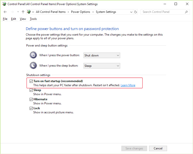
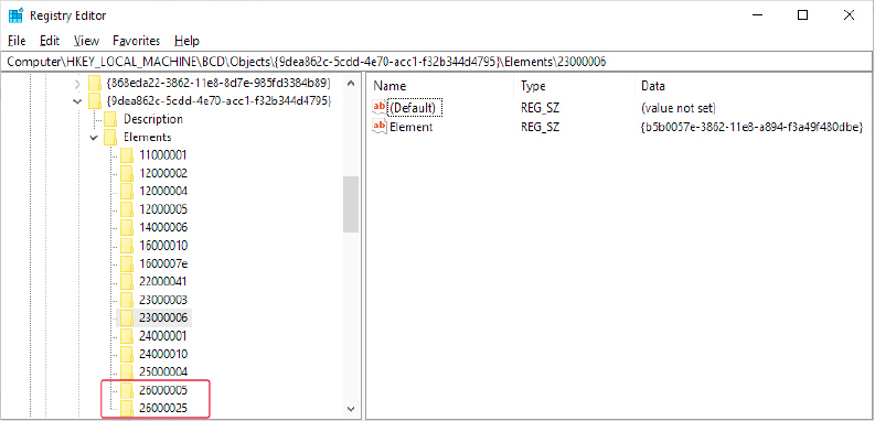
Windows Recovery Environment (WinRE)
The Windows Recovery Environment provides an assortment of tools and automated repair technologies to fix the most common startup problems. It includes six main tools:
■ System Restore Allows restoring to a previous restore point in cases in which you can’t boot the Windows installation to do so, even in safe mode.
■ System Image Recover Called Complete PC Restore or Automated System Recovery (ASR) in previous versions of Windows, this restores a Windows installation from a complete backup, not just from a system restore point, which might not contain all damaged files and lost data.
■ Startup Repair An automated tool that detects the most common Windows startup problems and automatically attempts to repair them.
■ PC Reset A tool that removes all the applications and drivers that don’t belong to the standard Windows installation, restores all the settings to their default, and brings back Windows to its original state after the installation. The user can choose to maintain all personal data files or remove everything. In the latter case, Windows will be automatically reinstalled from scratch.
■ Command Prompt For cases where troubleshooting or repair requires manual intervention (such as copying files from another drive or manipulating the BCD), you can use the command prompt to have a full Windows shell that can launch almost any Windows program (as long as the required dependencies can be satisfied)—unlike the Recovery Console on earlier versions of Windows, which only supported a limited set of specialized commands.
■ Windows Memory Diagnostic Tool Performs memory diagnostic tests that check for signs of faulty RAM. Faulty RAM can be the reason for random kernel and application crashes and erratic system behavior.
When you boot a system from the Windows DVD or boot disks, Windows Setup gives you the choice of installing Windows or repairing an existing installation. If you choose to repair an installation, the system displays a screen similar to the modern boot menu (shown in Figure 12-15), which provides different choices.
The user can select to boot from another device, use a different OS (if correctly registered in the system BCD store), or choose a recovery tool. All the described recovery tools (except for the Memory Diagnostic Tool) are located in the Troubleshoot section.

Figure 12-15 The Windows Recovery Environment startup screen.
The Windows setup application also installs WinRE to a recovery partition on a clean system installation. You can access WinRE by keeping the Shift key pressed when rebooting the computer through the relative shutdown button located in the Start menu. If the system uses the Legacy Boot menu, WinRE can be started using the F8 key to access advanced boot options during Bootmgr execution. If you see the Repair Your Computer option, your machine has a local hard disk copy. Additionally, if your system failed to boot as the result of damaged files or for any other reason that Winload can understand, it instructs Bootmgr to automatically start WinRE at the next reboot cycle. Instead of the dialog box shown in Figure 12-15, the recovery environment automatically launches the Startup Repair tool, shown in Figure 12-16.

Figure 12-16 The Startup Recovery tool.
At the end of the scan and repair cycle, the tool automatically attempts to fix any damage found, including replacing system files from the installation media. If the Startup Repair tool cannot automatically fix the damage, you get a chance to try other methods, and the System Recovery Options dialog box is displayed again.
The Windows Memory Diagnostics Tool can be launched from a working system or from a Command Prompt opened in WinRE using the mdsched.exe executable. The tool asks the user if they want to reboot the computer to run the test. If the system uses the Legacy Boot menu, the Memory Diagnostics Tool can be executed using the Tab key to navigate to the Tools section.
Safe mode
Perhaps the most common reason Windows systems become unbootable is that a device driver crashes the machine during the boot sequence. Because software or hardware configurations can change over time, latent bugs can surface in drivers at any time. Windows offers a way for an administrator to attack the problem: booting in safe mode. Safe mode is a boot configuration that consists of the minimal set of device drivers and services. By relying on only the drivers and services that are necessary for booting, Windows avoids loading third-party and other nonessential drivers that might crash.
There are different ways to enter safe mode:
■ Boot the system in WinRE and select Startup Settings in the Advanced options (see Figure 12-17).

Figure 12-17 The Startup Settings screen, in which the user can select three different kinds of safe mode.
■ In multi-boot environments, select Change Defaults Or Choose Other Options in the modern boot menu and go to the Troubleshoot section to select the Startup Settings button as in the previous case.
■ If your system uses the Legacy Boot menu, press the F8 key to enter the Advanced Boot Options menu.
You typically choose from three safe-mode variations: Safe mode, Safe mode with networking, and Safe mode with command prompt. Standard safe mode includes the minimum number of device drivers and services necessary to boot successfully. Networking-enabled safe mode adds network drivers and services to the drivers and services that standard safe mode includes. Finally, safe mode with command prompt is identical to standard safe mode except that Windows runs the Command Prompt application (Cmd.exe) instead of Windows Explorer as the shell when the system enables GUI mode.
Windows includes a fourth safe mode—Directory Services Restore mode—which is different from the standard and networking-enabled safe modes. You use Directory Services Restore mode to boot the system into a mode where the Active Directory service of a domain controller is offline and unopened. This allows you to perform repair operations on the database or restore it from backup media. All drivers and services, with the exception of the Active Directory service, load during a Directory Services Restore mode boot. In cases when you can’t log on to a system because of Active Directory database corruption, this mode enables you to repair the corruption.
Driver loading in safe mode
How does Windows know which device drivers and services are part of standard and networking-enabled safe mode? The answer lies in the HKLMSYSTEMCurrentControlSetControlSafeBoot registry key. This key contains the Minimal and Network subkeys. Each subkey contains more subkeys that specify the names of device drivers or services or of groups of drivers. For example, the BasicDisplay.sys subkey identifies the Basic display device driver that the startup configuration includes. The Basic display driver provides basic graphics services for any PC-compatible display adapter. The system uses this driver as the safe-mode display driver in lieu of a driver that might take advantage of an adapter’s advanced hardware features but that might also prevent the system from booting. Each subkey under the SafeBoot key has a default value that describes what the subkey identifies; the BasicDisplay.sys subkey’s default value is Driver.
The Boot file system subkey has as its default value Driver Group. When developers design a device driver’s installation script (.inf file), they can specify that the device driver belongs to a driver group. The driver groups that a system defines are listed in the List value of the HKLMSYSTEMCurrentControlSetControlServiceGroupOrder key. A developer specifies a driver as a member of a group to indicate to Windows at what point during the boot process the driver should start. The ServiceGroupOrder key’s primary purpose is to define the order in which driver groups load; some driver types must load either before or after other driver types. The Group value beneath a driver’s configuration registry key associates the driver with a group.
Driver and service configuration keys reside beneath HKLMSYSTEMCurrentControlSetServices. If you look under this key, you’ll find the BasicDisplay key for the basic display device driver, which you can see in the registry is a member of the Video group. Any file system drivers that Windows requires for access to the Windows system drive are automatically loaded as if part of the Boot file system group. Other file system drivers are part of the File System group, which the standard and networking-enabled safe-mode configurations also include.
When you boot into a safe-mode configuration, the boot loader (Winload) passes an associated switch to the kernel (Ntoskrnl.exe) as a command-line parameter, along with any switches you’ve specified in the BCD for the installation you’re booting. If you boot into any safe mode, Winload sets the safeboot BCD option with a value describing the type of safe mode you select. For standard safe mode, Winload sets minimal, and for networking-enabled safe mode, it adds network. Winload adds minimal and sets alternateshell for safe mode with command prompt and dsrepair for Directory Services Restore mode.
![]() Note
Note
An exception exists regarding the drivers that safe mode excludes from a boot. Winload, rather than the kernel, loads any drivers with a Start value of 0 in their registry key, which specifies loading the drivers at boot time. Winload doesn’t check the SafeBoot registry key because it assumes that any driver with a Start value of 0 is required for the system to boot successfully. Because Winload doesn’t check the SafeBoot registry key to identify which drivers to load, Winload loads all boot-start drivers (and later Ntoskrnl starts them).
The Windows kernel scans the boot parameters in search of the safe-mode switches at the end of phase 1 of the boot process (Phase1InitializationDiscard, see the “Kernel initialization phase 1” section earlier in this chapter), and sets the internal variable InitSafeBootMode to a value that reflects the switches it finds. During the InitSafeBoot function, the kernel writes the InitSafeBootMode value to the registry value HKLMSYSTEMCurrentControlSetControlSafeBootOptionOptionValue so that user-mode components, such as the SCM, can determine what boot mode the system is in. In addition, if the system is booting in safe mode with command prompt, the kernel sets the HKLMSYSTEMCurrentControlSet ControlSafeBoot OptionUseAlternateShell value to 1. The kernel records the parameters that Winload passes to it in the value HKLMSYSTEMCurrentControlSetControlSystemStartOptions.
When the I/O manager kernel subsystem loads device drivers that HKLMSYSTEMCurrentControlSetServices specifies, the I/O manager executes the function IopLoadDriver. When the Plug and Play manager detects a new device and wants to dynamically load the device driver for the detected device, the Plug and Play manager executes the function PipCallDriverAddDevice. Both these functions call the function IopSafebootDriverLoad before they load the driver in question. IopSafebootDriverLoad checks the value of InitSafeBootMode and determines whether the driver should load. For example, if the system boots in standard safe mode, IopSafebootDriverLoad looks for the driver’s group, if the driver has one, under the Minimal subkey. If IopSafebootDriverLoad finds the driver’s group listed, IopSafebootDriverLoad indicates to its caller that the driver can load. Otherwise, IopSafebootDriverLoad looks for the driver’s name under the Minimal subkey. If the driver’s name is listed as a subkey, the driver can load. If IopSafebootDriverLoad can’t find the driver group or driver name subkeys, the driver will not be loaded. If the system boots in networking-enabled safe mode, IopSafebootDriverLoad performs the searches on the Network subkey. If the system doesn’t boot in safe mode, IopSafebootDriverLoad lets all drivers load.
Safe-mode-aware user programs
When the SCM user-mode component (which Services.exe implements) initializes during the boot process, the SCM checks the value of HKLMSYSTEMCurrentControlSet ControlSafeBootOptionOptionValue to determine whether the system is performing a safe-mode boot. If so, the SCM mirrors the actions of IopSafebootDriverLoad. Although the SCM processes the services listed under HKLMSYSTEMCurrentControlSetServices, it loads only services that the appropriate safe-mode subkey specifies by name. You can find more information on the SCM initialization process in the section “Services” in Chapter 10.
Userinit, the component that initializes a user’s environment when the user logs on (%SystemRoot%System32Userinit.exe), is another user-mode component that needs to know whether the system is booting in safe mode. It checks the value of HKLMSYSTEMCurrentControlSetControlSafeBoot OptionUseAlternateShell. If this value is set, Userinit runs the program specified as the user’s shell in the value HKLMSYSTEMCurrentControlSetControlSafeBootAlternateShell rather than executing Explorer.exe. Windows writes the program name Cmd.exe to the AlternateShell value during installation, making the Windows command prompt the default shell for safe mode with command prompt. Even though the command prompt is the shell, you can type Explorer.exe at the command prompt to start Windows Explorer, and you can run any other GUI program from the command prompt as well.
How does an application determine whether the system is booting in safe mode? By calling the Windows GetSystemMetrics(SM_CLEANBOOT) function. Batch scripts that need to perform certain operations when the system boots in safe mode look for the SAFEBOOT_OPTION environment variable because the system defines this environment variable only when booting in safe mode.
Boot status file
Windows uses a boot status file (%SystemRoot%Bootstat.dat) to record the fact that it has progressed through various stages of the system life cycle, including boot and shutdown. This allows the Boot Manager, Windows loader, and Startup Repair tool to detect abnormal shutdown or a failure to shut down cleanly and offer the user recovery and diagnostic boot options, like the Windows Recovery environment. This binary file contains information through which the system reports the success of the following phases of the system life cycle:
■ Boot
■ Shutdown and hybrid shutdown
■ Resume from hibernate or suspend
The boot status file also indicates whether a problem was detected the last time the user attempted to boot the operating system and the recovery options shown, indicating that the user has been made aware of the problem and taken action. Runtime Library APIs (Rtl) in Ntdll.dll contain the private interfaces that Windows uses to read from and write to the file. Like the BCD, it cannot be edited by users.
Conclusion
In this chapter, we examined the detailed steps involved in starting and shutting down Windows (both normally and in error cases). A lot of new security technologies have been designed and implemented with the goal of keeping the system safe even in its earlier startup stages and rendering it immune from a variety of external attacks. We examined the overall structure of Windows and the core system mechanisms that get the system going, keep it running, and eventually shut it down, even in a fast way.