Infrastructure configuration as code
Depending on the size of your organization, you might deploy a couple of servers and then leave them in production for years, or, as we saw when it came to the (ongoing) retirement of Windows Server 2008 R2, well over a decade. Other organizations deploy servers on a more frequent basis. Some even use a process where rather than applying software updates to a production server and incurring downtime as the update is applied and the server rebooted, they find it faster to deploy a newly patched computer, to migrate the existing workload to the new host, and then to decommission the original server.
This type of iterative deployment is possible because the tools around managing the configuration of servers have evolved. Today, deploying and configuring a new server is no more bothersome than deploying an application would have been a decade ago. In this chapter, you’ll learn about how you can use Windows Server images, Windows Deployment Services, Virtual Machine Manager, Desired State Configuration, Puppet, and Chef to deploy and manage the configuration of computers and virtual machines running the Windows Server 2019 operating system.
Bare metal versus virtualized
Today, almost all new workloads are virtualized. For most organizations, virtualization hosts are the primary remaining physically deployed server, with almost all other workloads running as virtual machines. Unless you have specific reasons not to virtualize a workload, you should run Windows Server 2019 as a virtual machine (VM) rather than as a physically deployed server.
The security available with shielded VMs addresses one of the final objections that many organizations have had around deploying servers virtually rather than physically. With shielded VMs, you can provide the same level of security to a workload that you can to a physically deployed server sitting in a locked cage in a datacenter.
At present, your best bet when deploying virtualization hosts is to choose the Server Core installation option because this has a smaller installation footprint and a reduced attack surface compared to the Server with Desktop Experience option. When you deploy a Server Core virtualization host, you manage Hyper-V remotely from a privileged access workstation or a tool such as Windows Admin Center or Virtual Machine Manager.
Windows images
With Windows images, the entire operating system, as well as associated drivers, updates, and applications, is stored within a single file known as an image file. During installation, this image is applied to the target volume. Windows images use the Windows Imaging (WIM) file format, which has the following benefits:
Multiple deployment methods. You can use a variety of ways to deploy Windows images. While unusual these days, you can deploy .wim files using a traditional DVD-ROM, from a bootable USB drive, from a network share, or through specialized deployment technologies such as Windows Deployment Services (WDS) or System Center Virtual Machine Manager. While it is possible to use System Center Configuration Manager to deploy Windows Server, Configuration Manager is primarily used with client operating systems rather than server operating systems.
Editable. You can mount an image and edit it, enabling, disabling, or removing operating system roles and features as necessary.
Updatable. You can update an image without having to perform an operating system image capture.
The Windows Server 2019 installation media contain two .wim files in the Sources folder: Boot.wim and Install.wim. The installation media uses Boot.wim to load the preinstallation environment that you use to deploy Windows Server 2019. Install.wim stores one or more operating system images. For example, as Figure 3-1 shows, the Install.wim file available with the evaluation version of Windows Server 2019 contains four different editions of Windows Server 2019. Depending on the specifics of the hardware on which you are attempting to install Windows Server, you might need to add extra drivers to the boot.wim file. For example, you will need to add extra drivers if the Windows Server installation routine cannot access the storage device on which you want to install Windows Server because that device’s driver is included in the default boot image.

Figure 3-1 Windows Server 2019 editions
Modifying Windows images
The Deployment Image Servicing and Management (DISM) tool is a command-line tool that you can use to manage images in an offline state. You can use Dism.exe to perform the following tasks:
Enable or disable roles and features
List roles and features
Add, remove, and list software updates
Add, remove, and list software drivers
Add, remove, and list software packages in .appx format to a Windows image
For example, you can take the Install.wim file from the Windows Server installation media and use Dism.exe to mount that image, add new drivers and recent software updates to that image, and save those changes to an image all without having to perform an actual deployment. The advantage is that when you do use this updated image for deployment, the drivers and updates that you added are already applied to the image and you won’t have to install them as part of your post-installation configuration routine.
You can use the Microsoft Update Catalog (https://catalog.update.microsoft.com) to search for drivers for images that you use with physically deployed servers. This site stores all the certified hardware drivers, software updates, and hotfixes published by Microsoft. Once you download drivers and software updates, you can add them to your existing installation images by using Dism.exe or the appropriate PowerShell cmdlets in the DISM PowerShell module.
Servicing Windows images
As an IT professional responsible for deploying Windows Server, you need to ensure that your deployment images are kept up to date. The latest software updates should be applied to the image, and any new device drivers for commonly used server hardware should be included.
The main goals of an image servicing strategy are the following:
Ensure that the latest software updates and hotfixes are applied to the image before the image is deployed to new servers.
Ensure that the latest drivers are applied to the image before the image is deployed to new servers.
If you don’t take these steps, you’ll have to wait until after you’ve deployed the operating system before you can apply updates and drivers. While Windows Server updates are cumulative now, and you won’t need to spend hours updating an image from RTM, it’s quicker to have the most recent update already applied to the image than it is to wait for the server to deploy, retrieve the latest update, and then wait for it to download and then install. Having updates apply after deployment has occurred consumes a significant amount of time and also substantively increases network traffic. One of your aims when performing a deployment should be to get the server operational and hosting workloads as quickly as possible.
You can use the DISM (Deployment Image Servicing and Management) utility or the associated PowerShell cmdlets in the DISM PowerShell module to service the current operating system in an online state or perform offline servicing of a Windows image.
Servicing images involves performing the following general steps:
Mount the image so that it can be modified.
Service the image.
Commit or discard the changes made to the image.
Mounting images
By mounting an image, you can make changes to that image. When you mount an image, you link it to a folder. You can use File Explorer, Windows PowerShell, or Cmd.exe to navigate the structure of this folder and interact with it as you would any other folder located on the file system. Once the image is mounted, you can also use Dism.exe or PowerShell to perform servicing tasks, such as adding and removing drivers and updates.
A single WIM file can contain multiple operating system images. Each operating system image is assigned an index number, which you need to know before you can mount the image. You can determine the index number using Dism.exe with the /Get-wiminfo switch. For example, if you have an image named Install.wim located in the C:Images folder, you can use the following command to get a list of the operating system images it contains.
Dism.exe /get-wiminfo /wimfile:c:imagesinstall.wim
Figure 3-2 shows the result of this command and lists the images contained in Windows Server 2019. The Standard Evaluation Edition of Windows Server 2019 with the Server Core installation option is assigned index identity 1, the Standard Evaluation with Desktop Experience is assigned index identity 2, the Datacenter Evaluation with the Server Core installation option is assigned index identity 3, and the Datacenter Evaluation with Desktop Experience is assigned index identity 4.

Figure 3-2 Details of an operating system image
You can accomplish the same task using the Get-WindowsImage PowerShell cmdlet. For example, to view the contents of the image Install.wim in the C:Images folder, run the following command, as shown in Figure 3-3.
Get-WindowsImage -ImagePath c:imagesinstall.wim

Figure 3-3 Windows image details
Once you have determined which operating system image you want to service, you can use the /Mount-image switch with the Dism.exe command to mount that image. For example, to mount the Standard Edition of Windows Server 2019 from the Install.wim file that is available with the Evaluation Edition in the C:Mount folder, issue this command:
Dism.exe /mount-image /imagefile:c:imagesinstall.wim /index:2 /mountdir:c:mount
Alternatively, you can accomplish the same goal using the following Mount-WindowsImage command:
Mount-WindowsImage -ImagePath c:imagesinstall.wim -index 2 -path c:mount
Adding drivers and updates to images
Once you have mounted an image, you can start to service that image. When servicing images used to deploy Windows Server, the most common tasks are adding device drivers and software updates to the image. You can use the /Add-Driver switch with the Dism.exe command to add a driver to a mounted image. When using the switch by itself, you need to specify the location the driver’s .inf file. Rather than adding a driver at a time, you can use the /Recurse option to have all drivers located in a folder and its subfolders added to an image. For example, to add all of the drivers located in and under the C: Drivers folder to the image mounted in the C:Mount folder, use the following command.
Dism.exe /image:c:mount /Add-Driver /driver:c:drivers /recurse
Similarly, you could use the Add-WindowsDriver cmdlet to accomplish the same objective by issuing the command:
Add-WindowsDriver -Path c:mount -Driver c:drivers -Recurse
You can use the /Get-Driver option to list all drivers that have been added to the image and the /Remove-Driver option to remove a driver from an image. In PowerShell, you use the Get-WindowsDriver cmdlet and the Remove-WindowsDriver cmdlets. You can remove only the drivers that you or someone else has added to an image. You can’t remove any of the drivers that were present in the image when Microsoft published it. You might choose to remove an existing driver if the driver you added in the past has since been updated.
You can use Dism.exe with the /Add-Package switch to add packages that contain updates or packages in .cab or .msu format. Software updates are available from the Microsoft Update Catalog website in .msu format. For example, you can download an update from the Microsoft Update Catalog website named Cumulative Update For Windows Server 2019 for x64-based Systems (KB4505056) to the C:Updates folder on a computer, as shown in Figure 3-4.
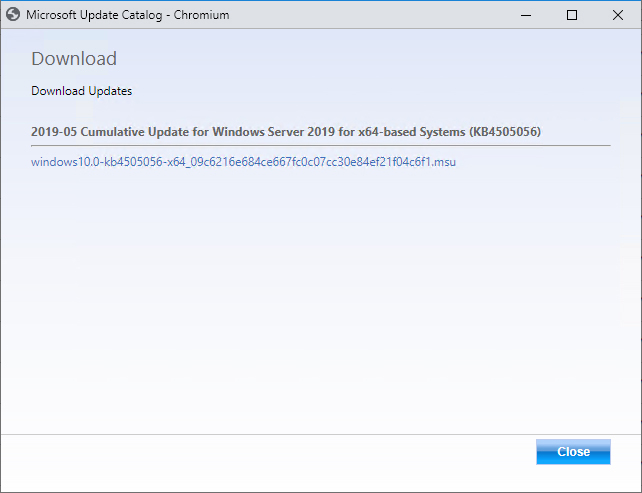
Figure 3-4 Downloading a cumulative update
If you mounted a WIM image of the Windows Server 2019 operating system in the C:Mount folder, you could apply the update to the image by using the command:
Dism.exe /image:c:mount /Add-Package /PackagePath:"c:updateswindows10.0-kb4505056-x64_09c6216e684ce667fc0c07cc30e84ef21f04c6f1.msu"
You can accomplish the same thing with the following Add-WindowsPackage command:
Add-WindowsPackage -path c:mount -packagepath "c:updatesAMD64-all-windows10.0-kb4505056-x64_09c6216e684ce667fc0c07cc30e84ef21f04c6f1.msu"
Adding roles and features
You can determine which features are available in a mounted operating system image by using the /Get-Features switch. Features include both Windows Server 2019 roles and features. For example, to learn which features are available in the image mounted in the C:Mount folder, use this command, as shown in Figure 3-5:
Dism.exe /image:c:mount /Get-Features

Figure 3-5 View features
You can enable or disable a specific feature using the /Enable-Feature switch. For example, to enable the NetFx3ServerFeatures feature, which enables the .NET Framework 3.5 server features in an image, use this command.
Dism.exe /image:c:mount /Enable-Feature /all /FeatureName:NetFx3ServerFeatures
Some features in the Windows Server image are in a state in which they are listed as having their payload removed, which means that the installation files for that feature are not included in the image. If you install a feature that had its payload removed when the operating system was deployed, the operating system can download the files from the Microsoft update servers on the Internet. You can also specify the location of the installation files. The installation files for the features that have had their payload removed in Windows Server are located in the Sourcessxs folder of the volume in which the installation media is located.
You can add these payload-removed features to an image by using Dism.exe and specifying the source directory. For example, to modify an image mounted in the C:Mount folder so that the Microsoft .NET Framework 3.5 features are installed and available, issue this command when the installation media is located on volume D, as shown in Figure 3-6:
Dism.exe /image:c:mount /Enable-Feature /all /FeatureName:NetFx3 /Source:d:sourcessxs

Figure 3-6 Enabling a feature
Committing an image
When you finish servicing an image, you can save your changes using the /Unmount-Wim switch with the /Commit option. You can discard changes using the /Discard option. For example, to make changes and then commit the image mounted in the C:Mount folder, use this command.
Dism.exe /Unmount-Wim /MountDir:c:mount /commit
You can use the Save-WindowsImage PowerShell cmdlet to save changes to an image without dismounting the image. You use the Dismount-WimImage cmdlet with the Save parameter to save the modifications that you’ve made to an image and then dismount it. For example, to dismount and save the image mounted in the C:Mount folder, run the command:
Dismount-WimImage -Path c:mount -Save
Once you have committed the changes, the .wim file that you originally mounted is updated with these modifications. You can then import this .wim file into WDS, use it to build a virtual hard disk, or use it with bootable USB installation media to deploy Windows Server 2019 with these updates and modifications already applied.
Build and capture
When you perform a build and capture, you deploy an operating system; provision that operating system with updates, applications, and drivers; and then capture that operating system for deployment. Build and capture is used less often with server operating systems because they rarely require the same sort of application deployment that is required for client operating systems. If you can just pull a container with an updated application down onto an operating system after deployment, there is little reason to include it in the image. Additionally, with tools such as Desired State Configuration, Chef, and Puppet, many post-installation and configuration tasks can be completely automated, reducing the hassle of post-installation configuration.
If your deployment strategy does involve the deployment and capture of Windows Server 2019, you need to remember that you’ll need to generalize the image prior to capture, removing any configuration information that is specific to the installation. You can perform this task using the Sysprep.exe utility. Sysprep.exe is included with Windows Server 2019 and is located in the C:WindowsSystem32Sysprep folder. When you use Sysprep.exe to prepare the image, you can configure the image to return to the system Out-of-Box Experience (OOBE), as shown in Figure 3-7. This is the same experience you get when Windows Server boots for the first time, though in this case all the updates, applications, and drivers included in the captured image are included in the newly deployed image.

Figure 3-7 Sysprep
You can use Dism.exe with the /Capture-Image switch or the New-WindowsImage PowerShell cmdlet to capture an image.
Answer files
Answer files present a traditional method of performing operating system deployment and configuration. While not as comprehensive as newer technologies such as Desired State Configuration (DSC) that assist not only in deployment but in ongoing configuration, answer files allow you to automate the process of deploying Windows Server.
Instead of having to manually select specific installation options and perform post–installation configuration actions such as joining a newly deployed server to an AD DS domain, you can automate the process with answer files. During setup, the Windows Server looks for a file on local and attached media named Autounattend.xml. If this file is present, Windows Server automatically uses the settings contained in the file to configure the new server deployment.
As its name suggests, Autounattend.xml uses the XML file format. Although it is certainly possible for you to manually edit this XML file using a text editor such as Notepad, this process is complicated, and you are likely to make errors that cause the file to not work. The Windows System Image Manager (known as Windows SIM) is a GUI-based tool that you can use to create an answer file. When using the tool, you must specify the image for which you want to create an answer file. Windows SIM then creates a catalog file for all the options that you can configure. After you configure all the settings that you want automated during installation and post-installation configuration, you can have the tool output an answer file using correct XML syntax. Windows SIM is included with the Windows Assessment and Deployment Kit (Windows ADK), which you can download from the Microsoft website.
To create an answer file using Windows SIM, perform the following steps:
Download and install Windows ADK from the Microsoft website using the installation defaults. You can do this with Chocolatey, covered later in this chapter, by running the following command:
Choco install -y windows-adk-all
Copy the Sourcesinstall.wim file from the Windows Server installation media to a temporary directory on the computer on which you have installed Windows ADK.
Open Windows SIM from the Start screen.
In the Windows SIM interface, click File, and then choose Select Windows Image. Open the Install.wim file.
Select an operating system image in the install image for which you wish to create an answer file. For example, Figure 3-8 shows the selection of the Standard edition with Desktop Experience operating system.

Figure 3-8 Select an image
When prompted to create a catalog file, click Yes.
Click File, New Answer File.
Use Windows SIM to select each component that you want to configure. Figure 3-9 shows how you can configure installation to join the adatum.com domain.

Figure 3-9 Windows System Image Manager
Windows Deployment Services
Windows Deployment Services (WDS) is a server role that you can deploy on computers running Windows Server. WDS enables you to deploy operating systems, including Windows 8.1, Windows 10, Windows Server 2012, Windows Server 2012 R2, Windows Server 2016, and Windows Server 2019, to computers over the network. WDS can send these operating systems across the network using multicast transmissions, which means that multiple computers receive the same operating system image while minimizing the use of network bandwidth. When you use multicast transmissions, the same amount of traffic crosses the network independently of whether you are deploying an operating system to 1 computer or to 50. WDS also can use unicast transmissions.
Deploying Windows Server through WDS involves performing the following steps:
An operating system deployment transmission is prepared on the WDS server.
The media access control (MAC) addresses of Pre-boot Execution Environment (PXE)–compliant network adapters are made available to the WDS server.
The computers that are targets of the transmission boot using their PXE-compliant network adapters.
These computers locate the WDS server and begin the operating system setup process. If the WDS server has been provisioned with an answer file, the setup completes automatically. If the WDS server has not been provisioned with an answer file, an administrator must enter setup configuration information.
Each WDS server can have only one unattended installation file for each processor architecture. Because unattended installation files differ between server and client, you either need to swap unattended files when you are switching between client and server or have multiple WDS servers. WDS can be used in conjunction with other technologies such as Desired State Configuration where an answer file only performs basic configuration tasks, with the substantial tasks completed by an advanced configuration technology.
WDS requirements
WDS clients need a PXE-compliant network adapter, which is rarely a problem because almost all modern network adapters are PXE-compliant. You can also use WDS to deploy Windows Server 2012 and later to virtual machines running under Hyper-V. The trick to doing this is to use a legacy rather than a synthetic network adapter when creating the virtual machine as a Generation 1 virtual machine. This isn't necessary when using Generation 2 virtual machines because the Generation 2 virtual machine network adapters support PXE booting.
If you have a computer that does not have a PXE-compliant network adapter, you can configure a special type of boot image known as a discover image. A discover image boots an environment, loading special drivers to enable the network adapter to interact with the WDS server. You create the boot image by adding the appropriate network adapter drivers associated with the computer that can’t PXE boot to the Boot.wim file from the Windows Server installation media.
WDS has the following requirements:
A Windows Server DNS server must be present on the local area network (LAN).
Prior to Windows Server 1810, an authorized Dynamic Host Configuration Protocol (DHCP) server must be present on the network. You can host WDS and DHCP on the same computer as long as you configure the options shown in Figure 3-10. Versions of Windows Server after 1810—including Windows Server 2019—can be used with third-party DHCP servers. Because this limits your ability to use IP address tracking through IPAM, using a third-party DHCP server if you are using WDS is not a recommended strategy.

Figure 3-10 WDS DHCP settings
If you install WDS from the Add Roles And Features Wizard, you can configure these settings automatically. Although the WDS server does not require a static IP address, it is good practice to ensure that infrastructure roles such as WDS always use a consistent network address. You can install WDS on computers running the Server Core version of Windows Server.
When installing WDS on Server Core, you have to specify the location of the source files or ensure that the server has a connection to the Internet, which enables them to be downloaded automatically. Although it is possible to manage WDS from Windows PowerShell, most administrators use the graphicsal WDS Remote Server Administration Tools (RSAT) from a computer running Windows 10, Windows Server 2016, or Windows Server 2019 with Desktop Experience.
Managing images
Images contain either entire operating systems or a version of a special stripped-down operating system known as Windows PE. Windows PE functions as a type of boot disk, enabling a basic environment to be loaded from which more complex maintenance and installation tasks can be performed. WDS uses four image types: boot image, install image, discover image, and capture image.
Boot Image. A special image that enables the computer to boot and begin installing the operating system using the install image. A default boot image, named Boot.wim, is located in the sources folder of the Windows Server installation media.
Install Image. The main type of image discussed in this chapter. Contains the operating system as well as any other included components, such as software updates and additional applications. A default install image, named Install.wim, is present in the sources folder of the Windows Server installation media. Install images can be in .vhd or .vhdx format, though you can only manage install images using the WDS console in Windows Server 2012 R2, Windows Server 2016, or Windows Server 2019.
Discover Image. This special image is for computers that cannot PXE boot to load appropriate network drivers to begin a session with a WDS server.
Capture Image. A special image type that enables a prepared computer to be booted so that its operating system state can be captured as an install image. You add capture images as boot images in WDS.
To import an image into WDS, perform the following steps:
Open the Windows Deployment Services console.
Click Install Images. From the Action menu, click Add Install Image.
Choose whether to create a new image group or to use an existing image group.
Specify the location of the image file.
In the Available Images page of the Add Image Wizard, select the operating system images that you want to add. When the image or images are added, click Next, Finish.
Configuring WDS
The installation defaults for WDS are suitable when you deploy the role in small environments. If you are deploying WDS in larger environments and do not choose to implement System Center Virtual Machine Manager for server operating system deployments, you might want to configure the options discussed in the following sections, which are available by editing the properties of the WDS server in the Windows Deployment Services console.
PXE response settings
With PXE response settings, you can configure how the WDS server responds to computers. As Figure 3-11 shows, you can configure WDS not to respond to any client computers (this effectively disables WDS), to respond to known client computers, or to respond to all computers but require an administrator to manually approve an unknown computer. Known computers are those that have prestaged accounts in Active Directory. You can prestage computers if you know the MAC address of the network interface card (NIC) that the computer uses. Vendors often supply a list of MAC addresses associated with computers when you purchase those computers, and you can use this list to prestage computer accounts.

Figure 3-11 PXE Response settings
You use the PXE Response Delay setting when you have more than one WDS server in an environment. You can use this setting to ensure that clients receive transmissions from one WDS server over another, with the server configured with the lowest PXE response delay having priority over other WDS servers with higher delay settings.
Client Naming Policy
The Client Naming Policy enables you to configure how computers installed from WDS are named if you aren’t using deployment options that perform the action. You can also use the settings on the AD DS tab, shown in Figure 3-12, to configure domain membership and organizational unit (OU) options for the computer account.

Figure 3-12 Client Naming Policy
WDS boot options
In the Boot options tab of the WDS server’s Properties dialog box, shown in Figure 3-13, you can configure how clients that PXE boot interact with the WDS server. You can also configure a default boot image for each architecture supported by WDS. By default, once a client has connected to a WDS server, someone must press the F12 key to continue deploying the operating system. In environments in which you are performing a large number of simultaneous deployments, requiring this level of manual intervention might substantially delay the deployment.

Figure 3-13 Boot options
Multicast options
The default settings of WDS have all computers that join the multicast transmission receiving the installation image at the same speed. If you frequently deploy operating systems, you are aware that sometimes there are one or two computers that have network adapters that slow transmission; transmissions that should take only 15 minutes now take half a day. You can configure the transfer settings on the Multicast tab, shown in Figure 3-14, so that clients are partitioned into separate sessions depending on how fast they can consume the multicast transmission. You still have those slow computers taking a long time to receive the image, but the other computers connected to the transmission can complete the deployment quicker.

Figure 3-14 WDS Multicast tab
Other options
Although you are less likely to need them, you can configure other options on the following tabs:
Advanced tab. You can configure WDS to use a specific domain controller and global catalog (GC) server. You can also configure whether WDS is authorized in DHCP. DHCP authorization occurs automatically when you install the WDS role.
Network tab. You can specify a User Datagram Protocol (UDP) port policy to limit when UDP ports are used with transmissions. You can also configure a network profile to specify the speed of the network, minimizing the chance that WDS transmissions slow the network down.
TFTP tab. You can specify maximum block size and Trivial File Transfer Protocol (TFTP) window size.
Configuring transmissions
You use WDS transmissions to set WDS to transfer the operating system image to PXE clients. When configuring a WDS transmission, you need to decide what type of multicast transmission you are going to perform in the Multicast Type page of the Create Multicast Transmission Wizard, as shown in Figure 3-15.

Figure 3-15 Multicast type
The difference between these options is as follows:
Auto-Cast. A transmission starts when a client requests the image. If another client requests the same image, the client joins the existing transmission, caching data from the current transfer and then retrieving data that was transmitted before the client joined the transmission. This is the best option to use when you are performing one-off deployments.
Scheduled-Cast. You choose either to start the transmission when a specified number of clients have joined, or you start the transmission at a particular date and time. Scheduled-Cast is the best option to use when you are deploying the same operating system image to a large number of computers.
To configure a WDS transmission, perform the following steps:
Open the Windows Deployment Services console, expand the WDS server from which you want to perform the deployment, and click Multicast Transmissions. In the Action menu, click Create Multicast Transmission.
Provide a name for the multicast transmission.
On the Image Selection page, specify which operating system image you want to deploy using the transmission.
On the Multicast Type page, specify whether you use Auto-Cast or Scheduled-Cast. If you choose Scheduled-Cast, select the number of clients or the transmission start time.
Driver groups and packages
You can stage device drivers on a WDS server by importing the device driver as a package. A driver package contains the extracted driver files. You can import the driver package into WDS by locating the driver's .inf file. When using the WDS console, you can either import individual driver packages or all the drivers in a set of folders.
In the WDS console, you can organize drivers into driver groups. A driver package can be a member of more than one group, and deleting a driver group does not delete the associated driver packages. You can use driver groups with filters to limit which driver packages are available to WDS clients.
Virtual Machine Manager
For most organizations, the majority of their server deployments involve virtual machines rather than deploying to bare metal physical hardware. While tools such as the Hyper-V console and WDS are adequate for smaller environments, if you need to deploy hundreds or thousands of virtual machines each year, you need a more comprehensive set of tools than those that are included with the Windows Server operating system.
System Center Virtual Machine Manager is one tool that you can use to manage your organization’s entire virtualization infrastructure, from virtualization hosts, clusters, and VMs, to managing the entire networking and storage stack. In this section, you’ll learn about VMM templates, storage, networking, and host groups.
Virtual machine templates
A Virtual Machine Manager VM template allows you to rapidly deploy virtual machines with a consistent set of settings. A VMM VM template is an XML object that is stored with a VMM library, and it includes one or more of the following components:
Guest Operating System Profile. A guest operating system profile that includes operating system settings.
Hardware Profile. A hardware profile that includes VM hardware settings.
Virtual Hard Disk. This can be a blank hard disk or a virtual hard disk that hosts a specially prepared—sysprepped, in the case of Windows-based operating systems— version of an operating system.
You can create VM templates based on existing virtual machines deployed on a virtualization host managed by VMM, based on virtual hard disks stored in a VMM library, or by using an existing VM template.
VM templates have the following limitations:
A VM template allows you to customize IP address settings, but you can only configure a static IP address for a specific VM from a pool when deploying that VM from the template.
Application and SQL Server deployment are only used when you deploy a VM as part of a service.
When creating a template from an existing VM, ensure that the VM is a member of a workgroup and is not joined to a domain.
You should create a separate local administrator account on a VM before using it as the basis of a template. Using the built-in administrator account causes the sysprep operation to fail.
VMM storage
VMM can use local and remote storage, with local storage being storage devices that are directly attached to the server and remote storage being storage available through a storage area network. VMM can use:
File storage. VMM can use file shares that support the SMB 3.0 protocol. This protocol is supported by file shares on computers running Windows Server 2012 and later. SMB 3.0 is also supported by third-party vendors of network-attached storage (NAS) devices.
Block storage. VMM can use block-level storage devices that host LUNs (Logical Unit Numbers) for storage using either the iSCSI, Serial Attached SCSI (SAS), or Fibre Channel protocols.
VMM supports automatically discovering local and remote storage. This includes automatic discovery of:
Storage arrays
Storage pools
Storage volumes
LUNs
Disks
Virtual disks
Using VMM, you can create new storage from storage capacity discovered by VMM and assign that storage to a Hyper-V virtualization host or host cluster. You can use VMM to provision storage to Hyper-V virtualization hosts or host clusters using the following methods:
From available capacity. Allows you to create storage volumes or LUNs from an existing storage pool.
From writable snapshot of a virtual disk. VMM supports creating storage from writable snapshots of existing virtual disks.
From a clone of a virtual disk. You can provision storage by creating a copy of a virtual disk. This uses storage space less efficiently than creating storage from snapshots.
From SMB 3.0 file shares. You can provision storage from SMB 3.0 file shares.
VMM supports the creation of a thin provisioned logical unit on a storage pool. This allows you to allocate a greater amount of capacity than is currently available in the pool, and it is only possible when:
The storage array supports thin provisioning
The storage administrator has enabled thin provisioning for the storage pool
VMM 2019 supports balancing of virtual disks across cluster-shared volumes to ensure that no single cluster shared volume is over-committed.
VMM networking
A VMM logical network is a collection of network sites, VLAN information, and IP subnet information. A VMM deployment needs to have at least one logical network before you can use it to deploy VMs or services. When you add a Hyper-V based virtualization host to VMM, one of the following happens:
If the physical adapter is associated with an existing logical network, it remains associated with that network once added to VMM.
If the physical adapter is not already associated with a logical network, VMM creates a new logical network, associating it with the physical adapter’s DNS suffix.
You can create logical networks with the following properties:
One Connected Network. Choose this option when network sites that compose this network can route traffic to each other, and you can use this logical network as a single connected network. You have the additional option of allowing VM networks created on this logical network to use network virtualization.
VLAN-Based Independent Networks. The sites in this logical network are independent networks. The network sites that compose this network can route traffic to each other, though this is not required.
Private VLAN (PVLAN) Networks. Choose this option when you want network sites within the logical network to be isolated independent networks.
You create network sites after you have created a VMM logical network. You use network sites to associate IP subnets, VLANs, and PVLANs with a VMM logical network.
Logical switches
VMM logical switches store network adapter configuration settings for use with VMM-managed virtualization hosts. You configure the properties of one or more virtualization host’s network adapters by applying the logical switch configuration information.
You should perform the following tasks before creating a logical switch:
Create logical networks and define network sites.
Install the providers for any Hyper-V extensible virtual switch extensions.
Create any required native port profiles for virtual adapters that you use to define port settings for the native Hyper-V virtual switch.
When you configure a VMM logical switch, you configure the following:
Extensions
Uplinks
Virtual Ports
Extensions
You use logical switch extensions to configure how the logical switch interacts with network traffic. VMM includes the following switch extensions:
Monitoring. Allows the logical switch to monitor but not modify network traffic.
Capturing. Allows the logical switch to inspect but not modify network traffic.
Filtering. Allows the logical switch to modify, defragment, or block packets.
Forwarding. Allows the logical switch to alter the destination of network traffic based on the properties of that traffic.
Uplink port profiles
Uplink port profiles specify which set of logical networks should be associated with physical network adapters. In the event that there are multiple network adapters on a virtualization host, an uplink port profile specifies whether and how those adapters should participate in teaming. Teaming allows network adapters to aggregate bandwidth and provide redundancy for network connections.
Virtual port profiles
You use port classifications to apply configurations based on functionality. The following port profiles are available:
SR-IOV. Allows a virtual network adapter to use SR-IOV (Single Root Input Output Virtualization)
Host Management. For network adapters used to manage the virtualization host using RDP, PowerShell, or another management technology
Network Load Balancing. To be used with network adapters that participate in Microsoft Network Load Balancing
Guest Dynamic IP. Used with network adapters that require guest dynamic IP addresses, such as those provided by DHCP
Live Migration Workload. Used with network adapters that support VM live migration workloads between virtualization hosts
Medium Bandwidth. Assign to network adapters that need to support medium-bandwidth workloads
Host Cluster Workload. Assign to network adapters that are used to support host clusters
Low Bandwidth. Assign to network adapters that need to support low-bandwidth workloads
High Bandwidth. Assign to network adapters that are used to support high-bandwidth workloads
iSCSI Workload. Assign to network adapters that are used to connect to SAN resources using the iSCSI protocol
Virtual machine networks
In VMM, virtual machines connect to a VMM logical network through a VMM virtual machine network. You connect a virtual machine’s network adapter to the virtual machine network rather than the logical network. You can have VMM automatically create an associated virtual machine network when you create a logical network. If you have configured a logical network to support network virtualization, you can connect multiple VM networks to the logical network, and they will be isolated from each other. Also, you can configure virtual networks to support encryption.
You can use network virtualization to configure logical networks in such a manner that different VM tenants can utilize the same IP address space on the same virtualization host without collisions occurring. For example, tenant alpha and tenant beta use the 172.16.10.x address space when their workloads are hosted on the same virtualization host cluster. Even though tenant alpha and tenant beta have virtual machines that use the same IPv4 address, network virtualization ensures that conflicts do not occur.
When you configure network virtualization, each network adapter is assigned two IP addresses:
Customer IP address. This IP address is the one used by the customer. The customer IP address is the address visible within the VM when you run a command such as ipconfig or Get-NetIPConfiguration.
Provider IP address. This IP address is used by and is visible to VMM. It is not visible within the VM operating system.
MAC address pools
A MAC address pool gives you a pool of MAC addresses that can be assigned to virtual machine network adapters across a group of virtualization hosts. Without MAC address pools, virtual machines are assigned MAC addresses on a per-virtualization host basis. While unlikely, it is possible the same MAC address may be assigned by separate virtualization hosts in environments with a very large number of virtualization hosts. Using a central MAC address pool ensures that doesn’t happen. When creating a MAC address pool, you specify a starting and an ending MAC address range.
Static IP address pools
An IP address pool is a collection of IP addresses that, through an IP subnet, is associated with a network site. VMM can assign IP addresses from the static IP address pool to virtual machines running Windows operating systems if those virtual machines use the logical network associated with the pool. Static IP address pools can contain default gateway, DNS server, and WINS server information. Static IP address pools aren’t necessary because VMs can be assigned IP address information from DHCP servers running on the network.
Private VLANS
VLANs segment network traffic by adding tags to packets. A VLAN ID is a 12-bit number, allowing you to configure VLAN IDS between the numbers 1 and 4095. While this is more than adequate for the majority of on-premises deployments, large hosting providers often have more than 5,000 clients, so they must use an alternate method to segment network traffic. A PVLAN is an extension to VLANS that uses a secondary VLAN ID with the original VLAN ID to segment a VLAN into isolated sub networks.
You can implement VLANs and PVLANs in VMM by creating a Private VLAN logical network. Private VLAN logical networks allow you to specify the VLAN and/or PVLAN ID, as well as the IPv4 or IPv6 network.
Adding a WDS to VMM
In a scalable environment, you'll need to add additional Hyper-V host servers on a frequent basis as either a standalone server or as part of a failover cluster to increase your capacity. While it's possible to use another technology to deploy new Hyper-V host servers to bare metal, the advantage of integrating virtualization host deployment with VMM is that you can fully automate the process. The process works in the following general manner:
Discovery of the chassis occurs. This may be through providing the chassis network adapter’s MAC address to VMM.
The chassis performs a PXE boot and locates the Windows Deployment Services (WDS) server that you have integrated with VMM as a managed server role. When you integrate WDS with VMM, the WDS server hosts a VMM provider that handles PXE traffic from the bare metal chassis started using the VMM provisioning tool.
The VMM provider on the WDS server queries the VMM server to verify that the bare metal chassis is an authorized target for managed virtualization host deployment. In the event that the bare metal chassis isn't authorized, WDS attempts to deploy another operating system to the chassis. If that isn't possible, PXE deployment fails.
If the bare metal chassis is authorized, a special Windows PE (Preinstallation Environment) image is transmitted to the bare metal chassis. This special Windows PE image includes a VMM agent that manages the operating system deployment.
Depending on how you configure it, the VMM agent in the Windows PE image can run scripts to update firmware on the bare metal chassis, configure RAID volumes, and prepare local storage.
A specially prepared virtual hard disk (in either .vhdx or .vhd format) containing the virtualization host operating system is copied to the bare metal chassis from a VMM library server.
The VMM agent in the Windows PE image configures the bare metal chassis to boot from the newly placed virtual hard disk.
The bare metal chassis boots into the virtual hard disk. If necessary, the newly deployed operating system can obtain additional drivers not included in the virtual hard disk from a VMM library server.
Post-deployment customization of the newly deployed operating system occurs. This includes setting a name for the new host and joining an Active Directory Domain Services domain.
The Hyper-V server role is deployed, and the newly deployed virtualization host is connected to VMM and placed in a host group.
The PXE server needs to provide the PXE service through Windows Deployment Services. When you add the VMM agent to an existing Windows Deployment Services server, VMM only manages the deployment process if the computer making the request is designated as a new virtualization host by VMM.
To integrate the WDS server with VMM to function as the VMM PXE server, you need to use an account on the VMM server that is a member of the local Administrators group on the WDS server. PXE servers need to be on the same subnet as the bare metal chassis to which they deploy the virtualization host operating system.
VMM host groups
Host groups allow you to simplify the management of virtualization hosts by allowing you to apply the same settings across multiple hosts. VMM includes the All Hosts group by default. You can create additional host groups as required in a hierarchical structure. Child host groups inherit settings from the parent host group. However, if you move a child host group to a new host group, the child host group retains its original settings, except for any PRO configuration. When you configure changes to a parent host group, VMM provides a dialog box asking if you would like to apply the changed settings to child host groups.
You can assign network and storage to host groups. Host group networks are the networks that are assigned to the host group. These resources include IP address pools, load balances, logical networks, and MAC address pools. Host group storage allows you to allocate logical units or storage pools that are accessible to the VMM server for a specific host group.
VMM virtualization host requirements
To be able to configure a bare metal hardware chassis so that it can function as a VMM managed Hyper-V virtualization host, the hardware chassis needs to meet the following requirements:
X64 processor. This needs to support hardware-assisted virtualization and hardware-enforced Data Execution Prevention (DEP). In some cases, it may be necessary to enable this support in BIOS.
PXE boot support. The hardware chassis must be able to PXE boot from a PXE-enabled network adapter. The PXE-enabled network adapter must be configured as a boot device.
Out-of-band (OOB) management support. System Center VMM can discover and manage the power states of hardware chassis that support BMC (Baseboard Management Controller). VMM supports the following protocols:
SMASH (Systems Management Architecture for Server Hardware) version 1 over WS-Management
DCMI (Datacenter Management Interface) version 1.0
IPMI (Microsoft Intelligent Platform Management Interface) version 1.5 or version 2.0
Placement rules
Placement rules allow you to configure how VMM identifies a suitable host for a VM deployment. Usually, this is based on the available resources on the virtualization host or the host cluster. By configuring host group placement rules, you can create rules that dictate the conditions under which a new VM can be placed on a virtualization host in the host group.
To add a placement rule, edit the properties of the host group, and on the Placement tab, click Add. You then specify a custom property and one of the following requirements:
Virtual Machine Must Match Host
Virtual Machine Should Match Host
Virtual Machine Must Not Match Host
Virtual Machine Should Not Match Host
Host reserves
Host reserves allow you to configure the resources that VMM should set aside for the host operating system. When VMM is going to place a new VM on a host, that host must be able to meet the VM’s resource requirements without exceeding the configured host reserves. You can configure host reserves for:
CPU
Memory
Disk I/O
Disk Space
Network I/O
Dynamic optimization
Dynamic optimization allows virtualization host clusters to balance workloads by transferring VMs between nodes according to the settings configured at the host group level. Whether the transfer occurs depends on whether the hardware resources on a node in the virtualization host cluster fall below the configured settings. Dynamic optimization applies only to clustered virtualization hosts and does not apply hosts that are not members of a cluster.
Infrastructure configuration as code
As infrastructure—including servers, storage, and networks—has increasingly become virtualized, configuration of that infrastructure has increasingly become defined by code. This means rather than having to build out a template image, it’s increasingly possible to define the properties of a server and the workload it hosts through a template written in a format such as JavaScript Object Notation (JSON), Ruby, or XML.
For example, with Azure, it’s possible to load a JSON template that defines the properties of a virtual machine workload as well as the network and storage settings associated with that workload. It also becomes increasingly possible to alter the properties of a running workload by modifying and reapplying the template rather than going through the workload’s management interface and applying changes manually.
Other advantages of infrastructure configuration as code include:
You can version that code so that you can roll back changes by simply applying an earlier version of a set of templates in the event that a set of changes cause unforeseen problems.
You can test the infrastructure code in a development environment before deploying it in a production environment. For example, you can ensure the infrastructure code to build your production VM workloads functions as expected on a test Hyper-V server before deploying the same code to your production Hyper-V failover cluster.
The WSLab project, hosted on GitHub at https://github.com/microsoft/WSLab, provides a set of PowerShell scripts that allow for the automatic creation of entire Hyper-V-based virtual machine testing labs. Running scripts allows you to do the following:
Create updated base operating system virtual machine hard disk images by:
Automatically downloading required operating system evaluation software from the Internet.
Using the WIM images stored on those evaluation versions of Windows operating systems, create sysprepped, virtual machine parent disks.
Applying the most recent software updates to ensure that the base operating system virtual machine hard disks are up to date.
Create Hyper-V internal and external networks.
Create fully functional virtual machines, including:
Creating new virtual machines from the base operating system virtual hard disks.
Connecting these newly created virtual machines to appropriate Hyper-V internal and external networks.
Injecting Desired State Configuration resources into the VMs from the host machine.
Injecting Unattend.xml files into the newly created VMs.
Invoking the DSC Local Configuration Manager to trigger the application of the DSC resources.
In Virtual Machine Manager, you can deploy a multitier virtual machine service by creating, configuring, and deploying the appropriate VM and service templates. Tools such as WSLab demonstrate that it’s possible to deploy entire environments quickly from scratch just with scripts, tools such as DSC, and the base operating system’s installation media.
Desired State Configuration
Desired State Configuration (DSC) is a configuration-management technology that’s built into Windows Server through PowerShell version 5 and higher. At a high level, a DSC configuration file describes how a computer should be configured rather than just a script that configures a computer. A component of DSC, called the Local Configuration Manager, takes a configuration file that describes how the server should be configured and ensures the server is configured in that way.
Almost all the tools required to use DSC are built into Windows Server 2019. You can also use DSC in a homogeneous Windows environment without the need to deploy a third-party operating system. A current disadvantage of DSC is that it can be challenging and complicated to configure and that it isn’t as developed as other third-party configuration tools where the tool forms the basis of an organization’s business model.
Not only does DSC perform initial configuration of a server, but it can also enforce that configuration. You can configure DSC so that changes made to the server’s configuration not made through DSC will automatically roll back the next time DSC runs. This makes DSC an excellent tool for ensuring that servers in your organization retain configurations that meet compliance requirements. If you manage configuration entirely through DSC, you perform configuration changes by modifying DSC configurations rather than signing onto a server and modifying the configuration manually.
DSC can also work in audit mode. When using DSC in audit mode, you can generate log data describing how a computer’s configuration deviates from that specified in a configuration file. This can be useful in determining how a computer’s configuration may have drifted from a baseline, and it can also be used to determine what updates need to be made to a DSC configuration file when modifications are made to a server that you wish to retain.
DSC configuration files
DSC configuration files describe how a computer should be configured. Configuration files require at least one node and require at least one configuration item per node. A configuration file can have multiple nodes, with different configuration items in each node. Generally, you create one configuration for each different computer type in your organization. For example, you create one for computers that host the DHCP server role, and you create another for computers that function as file servers.
The following hypothetical configuration would ensure that the WINS and Windows Server Backup features were present on a computer.
Configuration TestDscConfiguration {
Node “TEST-SVR” {
WindowsFeature InstallWINS {
Ensure = "Present"
Name = "WINS"
}
WindowsFeature InstallBackup {
Ensure = "Present"
Name = "Windows-Server-Backup"
}
}
}
TestDscConfiguration
When you run a DSC configuration script, it generates an MOF file. The MOF file is what the LCM (Local Configuration Manager) uses when determining which configuration to apply to a computer. You compile a configuration script by dot-sourcing it. For example, if you saved the above script as TestConfiguration.ps1 in the c:DSCTEST folder and .sourced it, the script would create a new folder named TestDscConfiguration; a new file named TEST-SVR.mof would be created in the same folder.
MOF files contain the configuration data that you want to apply to the Windows Server node. The MOF files are created by running DSC configuration files. You can deploy MOF files to the LCM on a Windows Server node by using the Push method to inject a file into a running computer, or you can configure a pull server from which nodes can retrieve MOF files and DSC resources.
Local Configuration Manager
The Local Configuration Manager (LCM) is present on each computer that uses DSC. The LCM is the component that takes a MOF file and DSC resources and uses them to enact a DSC configuration. You can view the current settings of the LCM using the Get-DscLocalConfigurationManager cmdlet, as shown in Figure 3-16.

Figure 3-16 LCM settings
DSC resources
DSC resources are used by the LCM. They can be PowerShell scripts or an item compiled into a DLL. Resources are stored in resource modules, which are distributed to the LCM to allow it to carry out the configuration instructions stored in the MOF. DSC resource modules must be present on any computer where they are used to create or apply a configuration script.
The PowerShell Gallery hosts a wealth of DSC resources that can form the basis of your DSC configuration scripts and configurations. DSC clients can obtain resources directly from DSC pull servers. If you are using another method of deploying configurations—such as the push method or copying method—you’ll need to ensure that the appropriate DSC resources are stored on the computer on which you want to configure using DSC.
DSC push model
You can push a MOF file to a target computer using the Start-DscConfiguration cmdlet and a PowerShell remoting connection. This is effective in smaller and test environments and can be used to push MOF files to target computers. For example, you might use this to push a MOF file to a test virtual machine running under client Hyper-V on your Windows 10 computer. The DSC push model requires that PowerShell remoting be enabled on each computer that is to be the target of a DSC push action. This is less of an issue with Windows Server 2019 because PowerShell remoting is enabled by default on this operating system.
Each time you use Start-DscConfiguration to push a new configuration to a node, the push action overwrites any existing configuration on the target node. Once you push the new configuration, the LCM on the target node begins immediately processing the MOF file. This makes the DSC push model a great way of testing configurations because you don’t have to wait for the DSC cycle to restart to process the update, something that is necessary when using DSC pull servers.
A substantial drawback to using DSC push is that any resources that are to be used by the MOF file must already be present on the node you are configuring through push. Should you wish to use new resources for a configuration, you’ll need to transfer them to the target node prior to pushing the new configuration.
DSC pull server
DSC pull servers are computers running Windows Server 2012 or later that function as central DSC repositories. Rather than push DSC configurations to each node, each node can be configured to poll a DSC pull server, downloading new MOF files and resources as they become available. DSC pull servers are almost always configured as web servers. It’s possible to use a standard file server as a pull server, but file servers lack some of the functionality of IIS-based pull servers, such as the ability to function as compliance servers. Compliance servers allow you to view a central repository of information about each node’s compliance with DSC configuration settings.
When you deploy a pull server, you specify a location to store MOF files and a location to store DSC resource files in zipped format. MOF files stored on a pull server use a Globally Unique Identifier (GUID) for identification. Each MOF file and DSC resource module zip file must be stored with an associated checksum file. You can generate checksum files using the New-DSCChecksum cmdlet.
Chef Infra Server
Chef Infra Server (referred to as Chef throughout this section) is a third-party configuration management solution. Unlike DSC, where you must build most of the infrastructure out yourself and you’re generally reliant upon a community to build resources for you unless you can build them yourself, Chef provides you with software and resources that you can use to manage the configuration of computers running a variety of operating systems. Chef allows you to manage servers running both Windows and Linux based operating systems.
Chef servers
Chef uses a client/server architecture. You manage the configurations that you want to deploy on a server as cookbooks, and the clients of those servers apply those cookbooks and recipes to Chef nodes to meet your configuration objectives. When deploying Chef, you have two primary options that you are responsible for managing: Hosted Chef and a Chef Server.
Hosted Chef
Hosted Chef is an instance of Chef Server hosted in the cloud by the Chef organization. The big benefit of Hosted Chef is that like any software as a service (SaaS) solution, the Chef organization takes care of the entire infrastructure. Hosted Chef requires that clients have a connection to the Internet, so they can communicate with the server. This makes Chef great for workloads running on Internet-connected networks but problematic for organizations who need configuration management on isolated networks.
Installing Chef Server
You can deploy Chef Server on-premises on a server running a Linux operating system. At present, you can’t deploy Chef Server on a computer running Windows Server 2019, though you can manage a Chef Server from any computer with a browser.
Chef Server is supported on the following operating systems:
Centos 6 and 7
Red Hat Enterprise Linux 6 and 7
SUSE Linux Enterprise Server 11 and 12
Ubuntu 16.04 and 18.04
Oracle Enterprise Linux 6 and 7
To install Chef Server on Linux, perform the following tasks:
Obtain the appropriate Chef Server package for the Linux server that you will use to host Chef Server from https://downloads.chef.io/chef-server and store it in a temporary directory on the Linux server that you want to function as the Chef server. In the following example, the package for Ubuntu LTS 16.04 is used.
Install the package. On a Linux server running Ubuntu, you would do this with a command similar to the following:
Sudo dpkg -i ./chef-server-core_12.19.31-1_amd64.deb
Once the package has installed, run the following command to begin configuration, which takes a moderate amount of time:
Sudo chef-server-ctl reconfigure
Once configuration has completed, create a new user. For example, run the following command to create a new user named sydneymelborne and store the certificate associated with that user in the ~/certs folder of the account used to deploy Chef server. (Note that the username is in lower case, and the password does need to be passed to the console.)
Sudo chef-server-ctl user-create sydneymelbourne Sydney Melbourne [email protected] P@ssw0rd --filename ~/certs/sydneymelbourne.pem
You can create an organization and associate the user that you created with that organization using the following command. In this case, the organization name is contoso. (Be sure that you enter the organization name in lowercase.)
Sudo chef-server-ctl org-create contoso “Contoso-Chef” --association_user sydneymelbourne --filename ~/certs/contoso.pem
To install the web-based management console, run the following command:
Sudo chef-server-ctl install chef-manage
Then use the following commands to configure the console:
Sudo check-server-ctl reconfigure
Sudo chef-manage-ctl reconfigure --accept-license
You can then verify that the server is functioning by using a standards-compliant web browser to navigate to the FQDN of the Chef server, as shown in Figure 3-17. You should sign in with the account created in step 4.
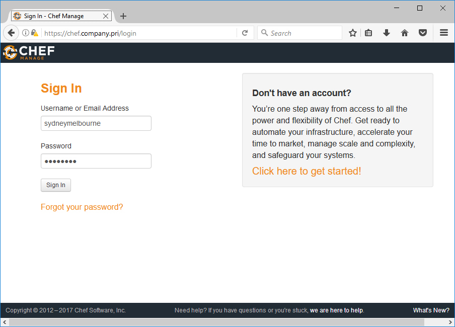
Figure 3-17 Chef console
If you navigate to the Administration node, you’ll be able to view the organization that you created and the users who are members of that organization, as shown in Figure 3-18.

Figure 3-18 Chef organization
Once you have verified the configuration of the console, you can install and configure Chef’s reporting capability by running the following commands:
Sudo chef-server-ctl install opscode-reporting
Sudo chef-server-ctl reconfigure
Sudo opscode-reporting-ctl reconfigure --accept-license
Chef Development Kit
You use the Chef Development Kit (ChefDK) to author recipes, cookbooks, and policies. You can install the Chef Development Kit by downloading the relevant files from Chef’s website; also, if you have Chocolatey configured, you can install the Chef Development Kit, as described later in this chapter, by running the following command from an elevated command prompt:
Choco install -y chefdk
Performing this installation gives you access to the ChefDK PowerShell prompt, which allows you to use PowerShell to interact with ChefDK.
Starter Kit
The Starter Kit is a package that you can download from your Chef server that contains all the information and files needed to connect to an organization hosted on your Chef server. You can find this package by clicking Starter Kit in the sidebar menu when you have the organization selected in the Administration tab, as shown in Figure 3-19.

Figure 3-19 Starter Kit
The Starter Kit is a zipped file that has the basic structure of a Git repository. You can add this file structure to a Git repository if you want to implement source control. The file knife.rb, shown opened in Visual Studio Code in Figure 3-20, contains the settings of the organization on the Chef Server.

Figure 3-20 Chef organization settings
To use ChefDK with the Chef Server, you need to have the TLS certificates assigned to the server present on the workstation on which you have ChefDK installed. Even if your computer trusts the TLS certificate, you’ll still need a local copy of the public certificate to use the Knife utility in the ChefDK to interact with your organization’s Chef server. You can retrieve the TLS certificate that is assigned to the Chef server by running the following command in the chef-repo folder from the Chef Development Kit shell that becomes available when you install the ChefDK. The certificate is added to the trusted certificates area of the Chef Git repository folder structure that was created when you unzipped the Starter Kit, as shown in Figure 3-21.

Figure 3-21 Acquire Chef certificate
You can verify that the certificate has installed correctly by running the following command from the chef-repo folder using the ChefDK PowerShell prompt:
Knife SSL check
Recipes and cookbooks
You use a Chef recipe to specify the configuration a Chef node should have. You bundle recipes into cookbooks and deploy cookbooks against Chef clients. A default Windows cookbook is available from the Chef website. You can download the current example Windows cookbook from Chef and the ohai cookbook (which is a dependency of the Windows cookbook) by running the following command from the chef-repocookbooks folder using the ChefDK PowerShell prompt:
Knife cookbook site download windows
Knife cookbook site download ohai
Doing so downloads both the Windows cookbook and the ohai cookbook in .tar and .zip format. You can use a utility such as 7-Zip to extract the cookbooks. Once extracted, place the cookbooks in the cookbooks folder.
You can use the Windows cookbook as a base cookbook on which you can create additional specific cookbooks. For example, to create a cookbook named wins-windows that installs the WINS server feature on a Windows Server computer, perform the following steps:
In the Chef-repoCookbooks folder, run the following ChefDK PowerShell command:
Chef generate cookbook wins-windows
Open the Chef-repocookbookswins-windows ecipesdefault.rb file in Visual Studio Code and add the following lines, as shown in Figure 3-22.
windows_feature “WINSRuntime” do
action :install
end

Figure 3-22 Default.rb
To configure the new cookbook’s dependency on the existing example Windows cookbook, open the Chef-repocookbookswins-windowsmetadata.rb file and add the following line, as shown in Figure 3-23:
depends ‘windows’

Figure 3-23 Configure dependencies
In the Chef-repoRoles folder, create a new file named wins-windows.rb and enter the following text, as shown in Figure 3-24.
name “wins-windows”
description “test WINS install”
run_list “recipe[wins-windows]”

Figure 3-24 wins-windows.rb
From the Chef-repoCookbooks folder, run the following command to push all current cookbooks from the computer that hosts ChefDK to the Chef server:
Knife cookbook upload --all
Next, change into the Chef-repoRoles folder and run the following command to create the relevant role:
Knife role from file .wins-windows.rb
You can verify that cookbooks are present on the Chef Server on the Policy tab of the Chef console, as shown in Figure 3-25.
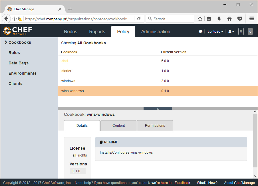
Figure 3-25 All Cookbooks
You can verify that the roles have uploaded correctly by checking the Roles section when the Policy tab is selected, as shown in Figure 3-26.

Figure 3-26 Chef roles
Deploying Chef agents
Deploying the Chef agent to a computer makes that computer a node in the Chef organization. The most reliable method of ensuring that a Chef node has all the relevant certificates and configuration settings required to communicate with a Chef Server is to perform a knife bootstrap deployment from a computer with ChefDK installed.
Prior to performing this deployment, you should update your tools to ensure that you have the latest versions of the deployment tools available. To do this, run the following command from the ChefDK prompt in the Chef-repo folder:
Gem update knife-windows
To deploy an agent to a Windows Server, you need to ensure that WinRM is configured on both the source and the target computer, and run the following command (where prodserver is the name of the target computer):
Knife bootstrap windows winrm prodserver.company.pri --winrm-user Administrator --winrm-password P@ssw0rd --node-name prodserver
You can verify that the client is installed on a node and registered with the Chef server by checking the Nodes tab in the management console.
Deploying Chef cookbooks and recipes
By applying a role to a node, you deploy the contents of that role, including cookbooks and their associated recipes. You can apply a role or recipe directly to a Chef node using the console by selecting the node in the console, editing the node’s Run List, and then assigning a Recipe or a Run List, as shown in Figure 3-27.

Figure 3-27 Edit Node Run List
The Run List will apply the next time the run applies. You can also manually trigger a run on the client by executing chef-client.bat from the C:WindowsSystem32 folder of an administrative command prompt. You can verify that the run has completed correctly by checking the Reports tab on the Chef console.
Puppet
Puppet is suitable for heterogeneous environments where you need to manage the configuration of both Linux and Windows servers. Puppet uses an architecture where a server named Puppet Master provides a central management point to computers that have the Puppet agent installed.
Puppet Master Server
The Puppet Master Server is only currently supported on hosts running a Linux- or UNIX-based operating system. If you are responsible for an environment that only has Windows servers, Puppet may not be a good fit because the Puppet Master Server can only be deployed on computers running the following operating systems:
RedHat Enterprise Linux, CentOS, Scientific Linux, and Oracle Linux Version 7 and 6 (x86_64)
Ubuntu version 16.04 (amd64)
SLES 12 SP1 (x86_64)
The Puppet Master Server stores configuration for all Puppet clients on the network. The Puppet Master Server requires at least 6 GB of RAM, four cores, a hostname that is accessible to other computers on the network, and accessibility on port 3000. You’ll likely need to manually configure the firewall to be open on the appropriate port. The administrator of the Puppet Master Server must have root user or have Sudo privileges on the host server.
To install the Linux computer as a Puppet Server, first connect to the server with an account that has the ability to elevate privileges and verify the computer’s hostname. Then perform the following steps:
You’ll need to download a tarball that is specific to your Linux distribution from the Puppet website to the Linux computer. Extract the tarball downloaded from the Puppet website using the following command:
Tar -xvf puppet-enterprise*
This extracts the Puppet installation files. Change to the directory that was created when you extracted the tarball, and start the installation script by typing the following command:
Sudo ./puppet-enterprise-installer
When prompted, select the guided installation. Once the installation is complete, you’ll need to open a browser and navigate to port 3000 on the address of the newly deployed Puppet Server. You’ll need to ignore any certificate errors and click Let's Get Started, as shown in Figure 3-28.

Figure 3-28 Puppet Server configuration
On the Puppet Master Component page, provide:
The FQDN of the Puppet Master Server
Any aliases that will be used by Puppet clients
Choose whether to install a PostgreSQL instance for the PuppetDB, and provide a console admin user password, as shown in Figure 3-29.

Figure 3-29 Install database and configure admin password
After the validation occurs, click Deploy Now. Puppet Server is deployed on the Linux server.
You can now connect to the web-based administration interface using the username admin and the password provided in step 4. The Inventory node lists all computers that are currently being managed by the Puppet server.
Deploying Puppet agent to Windows Server
The first step in deploying a Puppet agent to a computer running Windows Server 2019 is to configure the Puppet Master Server so that it has the correct agent installation software for an x64 version of Windows. You can do this by taking the following steps:
In the Puppet administration console, click Classification under the Nodes menu, and in the PE Infrastructure section shown, click PE Master.
On the Classes tab, in the Add New Class text box, type Windows, and then click pe_repo::platform::windows_x86_x64, as shown in Figure 3-30. Click Add Class, and then click Commit Changes. Unless you run the Puppet agent -t command on the Puppet Master Server, you’ll need to wait up to 30 minutes for the Puppet agent to wake up.

Figure 3-30 Configure Windows as a class
On your Windows Server, open a browser and navigate to https://<YOUR PUPPET MASTER HOSTNAME>:8140/packages/current/windows-x86_64/puppet-agent-x64.msi.
Run the downloaded installer. On the Welcome page, click Next, and then accept the terms of the License Agreement.
On the Configuration page, ensure that the FQDN of the Puppet Server matches the address of your Puppet Server, as shown in Figure 3-31, and click Install. Click Finish when the installation completes.

Figure 3-31 Puppet Agent Setup dialog box
Restart the computer, start an administrative PowerShell session, and run the following command, which initiates communication with the Puppet Master Server, allowing you to then trigger:
puppet agent -t
You’ll then need to return to the Puppet console, navigate to the Unsigned Certificates tab under Nodes, and then sign the unsigned node of the newly detected certificate of your new Windows Server Puppet client, as shown in Figure 3-32.

Figure 3-32 Sign unsigned certificates
Managing Windows Server configuration
Puppet manifest files describe a desired state of a managed server in terms of a list of resources and a set of attributes. You can use any text editor to write a manifest, though you might want to use a tool like Visual Studio Code because it supports syntax highlighting for Puppet syntax. Puppet manifests use the .pp extension.
You can use the Puppet Master web-based console to specify which manifests apply to particular Puppet clients, also termed nodes. Once Puppet is installed on a client, you can run Puppet commands from an elevated PowerShell session. Generally, you’ll build and test manifests on a development node using the command line tools. Then you can configure the manifests to be distributed and enforced by the Puppet Master Server.
You can perform the following tasks from an elevated PowerShell prompt on a computer that has the Puppet agent installed:
You can validate the syntax on a manifest using the Puppet parser validate command. For example, run the following command to check the syntax of a manifest file named services.pp:
Puppet parser validate c: est_manifestsservices.pp
Manifests are applied using the Puppet apply command. You can simulate a Puppet cycle using the --noop option, which runs Puppet in non-enforcement mode. For example, to simulate a Puppet cycle against the services.pp manifest, run the command:
Puppet apply c: est_manifestsservices.pp --noop
Once you’ve checked a manifest in non-enforcement mode, you can enforce the configuration using Puppet Apply.
Puppet agent allows you to retrieve compiled catalogs from a Puppet Master. By default, this cycle runs every 30 minutes.
Puppet Windows Module Pack
Puppet Forge is an online community for modules that are submitted by people in the Puppet community, as well as people who work for the organization. Because an extensive community exists around Puppet, it’s likely that someone has already written a module to perform a configuration task that you want to perform. You can take their hard work and use it to help configure the systems in your organization.
The Windows module pack is a collection of Puppet modules that you can use to perform common administrative tasks. To install the Windows Module Pack, open an administrative PowerShell prompt on a computer with the Puppet Agent installed, and run the following command:
Puppet module install puppetlabs/windows
The Puppet Windows Module pack includes tools that allow you to use Puppet to manage the following:
Read, create, and write registry keys with the registry module.
Remotely manage the execution of PowerShell scripts with the powershell module.
Manage PowerShell DNS resources using the dsc module.
Configure fine-grained access control permissions using the acl module.
Manage WSUS client configuration using the wsus_client module.
Configure which roles and features are installed using the windowsfeature module.
Download files from various locations using the download_file module.
Build and manage IIS sites and virtual applications using the iis module.
Manage the deployment of software packages using the chocolatey module.
Configure environment variables using the windows_env module.
While not comprehensive, you should now have a foundation-level understanding of the functionality of what you can do with Puppet, and whether it is worthy of further investigation in terms of inclusion as a part of your Windows Server administration toolkit.
Package-management utilities
Configuration of servers and applications through tools like DSC, Puppet, and Chef provide an example of one way that the process of Windows server administration has changed in the last decade. Another way that things have changed is through the use of package-management utilities. Rather than the traditional process of downloading the current version of software from a vendor’s website, vendors are increasingly publishing their software in centralized repositories that you can access through package-management utilities. The benefit of package-management utilities is that they provide a central location for obtaining software, updating, and removing software applications.
If you’ve used a Debian-derived flavor of Linux, you’ll be familiar with the Apt-get utility. Apt-get allows you to install any package prepared for Debian. It also allows you to update packages and the operating system. You can even use Apt-get to perform an entire operating system upgrade.
While not yet as advanced as Apt-get, package-management on Windows follows the paradigm that’s been available in the Open Source world for several decades. Windows Server both directly and indirectly now supports package management, either directly through cmdlets in the PackageManagement Windows PowerShell module or indirectly through package providers such as Chocolatey.
Windows Server 2019 includes native support for the installation of a variety of different package-management providers through PowerShell. Some providers make PowerShell resources available, and others make pre-packaged software available that you would otherwise download from the Internet and manually install. You can view which package providers are accessible by default to a Windows Server 2019 installation by using the Find-PackageProvider cmdlet, shown in Figure 3-33. In this chapter, you’ll learn about the PowerShell Gallery and Chocolatey. In later chapters, you’ll learn about specific providers, such as the DockerMsftProvider, which contains the tools used to manage Windows Server and Hyper-V containers; in Chapter 10, you’ll learn about the ability to download containers that run full containerized isolated versions of Microsoft server applications including SQL Server 2016 community edition.

Figure 3-33 Package providers
PowerShell Gallery
PowerShell Gallery is a provider that functions as a clearinghouse for PowerShell-related tools and content. The PowerShell team publishes content to the gallery, as do other PowerShell enthusiasts and MVPs. This means that it’s fairly likely that if there is a script, cmdlet, or a module that does something you think quite a few people would need to do, someone has probably already created it and published it to the PowerShell gallery. You can interact with PowerShell Gallery with the PowerShellGet module. You can use this module to access cmdlets that do the following:
Use Find-Module and Find-Script to find items in the gallery.
Use Save-Module and Save-Script to save items from the gallery.
Use Install-Module and Install-Script to install items from the gallery.
Use Publish-Module and Publish-Script to publish items to the gallery.
Add a custom repository to the gallery using Register-PSRepository.
Chocolatey
Chocolatey is perhaps the most well-known package provider available for Windows operating systems. It has a very extensive collection of software packages, with anything from commonly used applications such as 7-Zip and Visual Studio Code, to administration platforms such as Windows ADK. Chocolatey can also be integrated with Puppet, Chef, and DSC.
Chocolatey also runs very well on the Server Core installation option of Windows Server 2019, as well as within Windows Server and Hyper-V containers. It can be substantially quicker to use Chocolatey to retrieve and install a package; for example, it is quicker to use Chocolatey to install the Windows ADK with all options in the default location on a computer running the Server with Desktop Experience option. To do so, run the following command:
Choco install -y windows-adk-all
This requires substantially less time than searching the Microsoft website, downloading all the necessary prerequisites, and running the installation routine.
To install Chocolatey, you’ll need to set the PowerShell execution policy to unrestricted using the following command:
Set-ExecutionPolicy Unrestricted
Then you’ll need to run the following PowerShell command:
iwr https://chocolatey.org/install.ps1 -UseBasicParsing | iex
This installs Chocolatey and all its dependencies on the local computer.
Chocolatey has the following advantages when it comes to software deployment on servers:
Makes the deployment of software extremely simple. Once Chocolatey is installed, further packages can be installed with one line of code.
Packages are downloaded and installed with one command. You don’t need to download a file, unzip it, run the installer, and answer the questions of an inquisitive wizard.
Package dependencies are automatically installed when you attempt to install a package.
Maintainers often regularly update packages. This means that you can update all software installed via Chocolatey on a system by running the following command:
Chocolatey update all
Chocolatey has the following disadvantages:
Usually requires that the computer you are deploying software on be connected to the Internet. You can configure internal repositories, but you’ll have to manage and maintain them yourself, including validating the quality of the software found in those repositories.
Packages are usually installed in default locations with default settings. You don’t get the installation customization options that you get when you install software manually.
The provenance of the software isn’t clear. While it’s reasonable to assume that the software is safe, even large vendor app stores have apps that are infected with malware.
Using a simple script, you can install Chocolatey and then use it to download and install a common set of packages. You can also set up your own Chocolatey repository of packages that hosts only packages that you trust. You can then point a local Chocolatey instance at that repository and use it to quickly install software on newly deployed computers running a Windows operating system.