Storage spaces and storage pools
Storage-related PowerShell cmdlets
Windows Server 2019 provides several software-defined storage solutions that allow you to have complex storage configurations managed by the Windows Server operating system, rather than having to manage storage solutions using storage hardware–specific vendor management tools. Many of the storage service solutions available in Windows Server are used by Microsoft in their Azure datacenters where storage provisioning, performance, resiliency, and redundancy are all managed through software rather than through specific hardware devices.
Storage spaces and storage pools
Storage spaces and storage pools were first introduced to Windows Server with the release of Windows Server 2012. A storage pool is a collection of storage devices that you can use to aggregate storage. You expand the capacity of a storage pool by adding storage devices to the pool. A storage space is a virtual disk that you create from the free space that is available in a storage pool. Depending on how you configure it, a storage space can be resilient to failure and have improved performance through storage tiering.
You manage storage spaces and storage pools through Windows Admin Center, PowerShell, the RSAT Tools, or Server Manager.
Storage pools
A storage pool is a collection of storage devices—usually disks but can also include items such as virtual hard disks—from which you can create one or more storage spaces. A storage space is a special type of virtual disk that has the following features:
Resilient storage. Configure to use disk mirroring or parity in the structure of the underlying storage (if available). Resilience is discussed later in this chapter.
Tiering. Configure to leverage a combination of SSD and HDD disks to achieve maximum performance. Tiering is discussed later in this chapter.
Continuous availability. Storage spaces integrate with failover clustering, and you can cluster pools across separate nodes within a single failover cluster.
Write-back cache. If a storage space includes SSDs, a write-back cache can be configured in the pool to buffer small random writes. These random writes are then later offloaded to SSDs or HDDs that make up the virtual disk in the pool.
Multitenancy. You can configure Access Control Lists on each storage pool. This allows you to configure isolation in multitenant scenarios.
To add storage to a storage pool, perform the following general steps:
In Server Manager, navigate to the Storage Pools node under the Volumes node of the File And Storage Services workspace. In this workspace, you will see available storage that hasn’t been allocated in the Primordial pool, as shown in Figure 7-1. The Primordial pool is the collection of disks that have not been provisioned.

Figure 7-1 Primordial storage
On the Tasks menu, click New Storage Pool. You can also use the Tasks menu to rescan storage. You might need to use that option if you can’t see the storage in the Primordial pool that you want to add to a potential storage pool.
On the Storage Pool Name page of the New Storage Pool Wizard, specify a name for the storage pool and select which group of available disks you want to allocate to the storage pool. By default, the disks in the Primordial pool will be selected.
On the Physical Disks page, specify which available disks you want to add to the new pool. Figure 7-2 shows three disks being allocated using the Automatic allocation type and one disk being allocated as a Hot Spare type. Hot Spares will be swapped in if the existing disk in the storage pool fails.

Figure 7-2 Adding disks
On the confirmation page, review your settings and click Create. When the pool is created, click Close.
You can add and remove disks from an existing storage pool. To add disks to an existing storage pool, perform the following steps:
In the Storage Pools node, verify that the disks that you want to add to the pool are available in the Primordial pool.
Right-click the storage pool where you wish to add the additional disks and click Add Physical Disk.
In the Add Physical Disk dialog box, select the disks from the Primordial pool that you wish to add to the existing storage pool and specify which Allocation type they will use. You can choose between Automatic, Hot Spare, and Manual. Figure 7-3 shows two disks being added using the Automatic allocation type.

Figure 7-3 Adding disks to the existing pool
To remove a disk from an existing storage pool, perform the following steps:
In the Storage Pools node, select the storage pool from which you want to remove the disk.
In the list of physical disks, select the disk that you want to remove. You can right-click the disk within the pool and select the Toggle Drive Light option, shown in Figure 7-4, as a way of ensuring that you are removing the correct disk.

Figure 7-4 Toggle Drive Light
Once you are ready to remove the appropriate disk from the pool, right-click the disk, and select the Remove Disk option.
You will be presented with a warning message informing you that the operating system will attempt to rebuild virtual disks that store data on the disk that you are removing from the pool. This can only happen if there are enough disks remaining in the pool to store the data that is currently stored on the physical disk that has been removed from the pool.
Storage space resiliency
When creating a virtual disk on a storage pool that has enough disks, you can choose between several Storage Layouts, as shown in Figure 7-5.
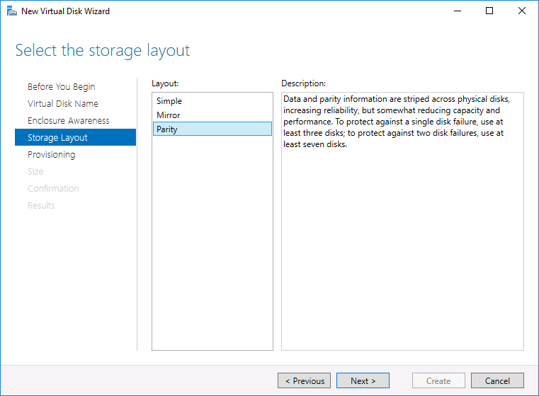
Figure 7-5 Choosing the Storage Layout
These options provide the following benefits:
Mirror. Multiple copies of data are written across separate disks in the pool, which protects the virtual disk from failure of the physical disks that constitute the storage pool. Mirroring can be used with storage tiering. Depending on the number of disks in the pool, Windows Server 2019 storage spaces provide two-way or three-way mirroring. Two-way mirroring writes two copies of data, and three-way mirroring writes three copies of data. Three-way mirroring provides better redundancy, but it also consumes more disk space.
Parity. Similar to RAID 5, parity data is stored on disks in the array that are separate from where data is stored. Parity provides greater capacity than using the Mirror option, but it has the drawback of slower write performance. Windows Server 2019 provides two types of parity: Single Parity and Dual Parity. Single Parity provides protection against one failure at a time. Dual Parity provides protection against two failures at a time. You need to have a minimum of three disks for Single Parity and a minimum of seven disks for Dual Parity. You get the option to select between Single Parity and Dual Parity when configuring storage layout when there are more than seven disks.
Simple. This option provides no resiliency for the storage, which means that if one of the disks in the storage pool fails, the data on any virtual hard disks built from that pool will also be lost.
If you configure disks in the storage pool that use the Hot Spare option, storage spaces will be able to automatically repair virtual disks that use the Mirror or Parity resiliency options. It’s also possible for automatic repairs to occur if spare unallocated capacity exists within the pool.
Storage space tiering
Storage space tiering allows you to create a special type of virtual disk from a pool of storage that is a combination of SSD and traditional HDD disks. Storage tiering provides the virtual disk with performance similar to that of an array built out of SSD disks but without the cost of building a large capacity array composed of SSD disks. It accomplishes this by moving frequently accessed files to faster physical disks within the pool, thus moving less-frequently accessed files to slower storage media.
You can only configure storage tiers when creating a virtual disk if there is a mixture of physical disks with the HDD and the SSD disk type in the pool upon which you want to create the disk. Once the disk is created, you cannot undo storage tiering from a virtual disk. You configure storage tiering for a virtual disk by selecting the Create Storage Tiers On This Virtual Disk option during virtual disk creation, as shown in Figure 7-6.

Figure 7-6 Enable storage tiering
One challenge when configuring storage tiering is ensuring that you have media marked as SSD and HDD in the pool. While media will usually be recognized correctly, in some cases you must specify that a disk is of the SSD type, which allows storage tiering to be configured.
You can specify the disk media type using the following PowerShell procedure:
First determine the storage using the Get-StoragePool cmdlet.
To view whether physical disks are configured as SSD or HDD, use the Get-StoragePool cmdlet and then pipe that cmdlet to the Get-PhysicalDisk cmdlet, as shown in Figure 7-7.

Figure 7-7 View disk media types
For example, to view the identity and media type of physical disks in the storage pool named Example-Pool, issue the command:
Get-StoragePool -FriendlyName ExamplePool | Get-PhysicalDisk | Select UniqueID, MediaType, Usage
Once you have determined the UniqueIDs of the disks that you want to configure as the SSD type, you can configure a disk to have the SSD type by using the Set-PhysicalDisk cmdlet with the UniqueID parameter and the MediaType parameter set to SSD. Similarly, you can change the type back to HDD by setting the MediaType parameter to HDD.
Thin provisioning and trim
Thin provisioning allows you to create virtual disks where you specify a total size for the disk, but only the space that is actually used will be allocated. For example, with thin provisioning, you might create a virtual hard disk that can grow to 500 GB in size but is only currently 10 GB in size because only 10 GB of data is currently stored on the volumes hosted on the disk. Figure 7-8 shows where you select the Provisioning Type in the New Virtual Disk Wizard.

Figure 7-8 Thin provisioning
You can view the amount of space that has been allocated to a thin-provisioned virtual disk, and you can see the total capacity in the Virtual Disks area when the Storage Pools node is selected in the Server Manager console, as shown in Figure 7-9. When you create a virtual disk, the maximum disk size available is determined by the amount of free space on the physical disks that make up the storage pool, rather than the maximum capacity of the existing thin-provisioned disks. For example, if you have a storage pool with two 10-TB physical disks, you can create more than two thin-provisioned disks that have a maximum size of 10 TB. You can create thin-provisioned disks 10 TB in size as long as the actual allocated space on the storage pool doesn’t exceed 10 out of the 20 available. It is possible to create thin-provisioned disks in such a way that the total thin-provisioned disk capacity exceeds the storage capacity of the underlying storage pool. If the space is overallocated, you’ll need to monitor how much of the underlying storage pool capacity is consumed and add disks to the storage pool because that capacity is exhausted.

Figure 7-9 Capacity and allocation
Trim is an automatic process that reclaims space when data is deleted from thin provisioned disks. For example, if you have a 10-TB thin-provisioned virtual disk that stores 8 TB of data, 8 TB will be allocated from the storage pool that hosts that virtual disk. If you delete 2 TB of data from that thin-provisioned virtual disk, trim ensures that the storage pool that hosts that virtual disk can reclaim that unused space. The 10-TB thin-provisioned virtual disk will appear to be 10 TB in size, but after the trim process is complete, it will only consume 6 TB of space on the underlying storage pool. Trim is enabled by default.
Creating virtual disks
A storage space virtual disk is composed from capacity available in the storage pool. As long as there is available capacity, you can create multiple virtual disks from a single storage pool. To create a new virtual disk using an existing storage pool, perform the following steps:
In Server Manager, navigate to the Storage Pools node under the Volumes node of the File And Storage Services workspace. In the Tasks menu of the Virtual Disks area, select New Virtual Disk.
On the list of available storage pools, shown in Figure 7-10, select an available storage pool upon which to create a new virtual disk and click OK.

Figure 7-10 Select a storage pool
On the Enclosure Awareness page, select whether you want to enable Enclosure Awareness. Doing so will mean that copies of data are stored across separate storage enclosures. For enclosure awareness to work, you’ll need multiple enclosures to host the disks that make up the storage pool.
On the Storage Layout page, you will be presented with the available layout options. Depending on the type and number of disks, you can choose between Simple, Mirror, and Parity.
On the Provisioning Type page, you can choose between thin and fixed provisioning.
On the Specify The Size of the Virtual Disk page, shown in Figure 7-11, you can choose a size for the disk. If you choose the Thin provisioning option, which you saw in Figure 7-8, the maximum amount of space in the storage pool is not listed. If you chose the Fixed option (back in Figure 7-8), the total amount of storage currently available in the pool is shown.

Figure 7-11 Specify the Virtual Disk size
On the Confirmation page, verify that the settings match what you intend and click Create.
Storage Spaces Direct
Storage Spaces Direct allows you to use Windows Server with locally attached storage to create highly available software-defined storage. Storage Spaces Direct (which uses the S2D abbreviation because the SSD abbreviation is already used for solid-state disks) provides a form of distributed, software-defined, shared-nothing storage that has similar characteristics to RAID in terms of performance and redundancy. S2D allows you to create volumes from a storage pool of physical drives that are attached to multiple nodes that participate in a Windows Server failover cluster. Storage Spaces Direct functions as a replacement for expensive large-scale hardware storage arrays. S2D is only available with the Datacenter Edition of Windows Server.
Storage Spaces Direct has the following properties:
You can scale out by adding additional nodes to the cluster.
When you add a node to a cluster configured for Storage Spaces Direct, all eligible drives on the cluster node will be added to the Storage Spaces Direct pool.
You can have between 2 and 16 nodes in a Storage Spaces Direct failover cluster.
It requires each node to have at least two solid state drives and at least four additional drives.
A cluster can have more than 400 drives and can support more than 4 petabytes of storage.
Storage spaces direct works with locally attached SATA, SAS, persistent memory, or NVMe drives.
Cache is automatically built from SSD media. All writes up to 256 KB and all reads up to 64 KB will be cached. Writes are then de-staged to HDD storage in optimal order.
Storage Spaces Direct volumes can be part mirror and part parity. To have a three-way mirror with dual parity, it is necessary to have four nodes in the Windows Server failover cluster that hosts Storage Spaces Direct.
If a disk fails, the plug-and-play replacement will automatically be added to the storage spaces pool when connected to the original cluster node.
A storage spaces direct cluster can be configured with rack and chassis awareness as a way of further ensuring fault tolerance.
Storage Spaces Direct clusters are not supported where nodes span multiple sites.
While NTFS is supported for use with S2D clusters, ReFS is recommended.
S2D supports two deployment options:
Hyper-Converged. With the Hyper-Converged deployment option, both storage and compute resources are deployed on the same cluster. This has the benefit of not requiring you to configure file server access and permissions and is most commonly used in small to medium sized Hyper-V deployments.
Converged. With the converged (also known as “disaggregated”) deployment option, storage and compute resources are deployed in separate clusters. Often used with Hyper-V Infrastructure as a Service (IaaS) deployments, a scale-out file server is deployed on S2D to provide network attached storage over SMB3 file shares. The compute resources for the IaaS virtual machines are located on a separate cluster to the S2D cluster.
Storage Spaces Direct in Windows Server 2019 supports nested resiliency. Nested resiliency is a capability designed for two-server S2D clusters that allows storage to remain available in the event of multiple hardware failures. When nested resiliency is configured, volumes can remain online and accessible even if one server goes offline and a drive fails. Nested resiliency only works when a cluster has two nodes. Nested resiliency requires a minimum of four capacity drives per server node and two cache drives per server node.
S2D resiliency types
S2D resiliency options are dependent on how many fault domains are present, the failure tolerance required, and the storage efficiency that can be achieved. A fault domain is a collection of hardware, such as a rack of servers, where a single failure can affect every component in that collection.
Table 7-1 lists the different resiliency types, failure tolerances, storage efficiencies, and minimum fault domains.
Table 7-1 S2D resiliency
Resiliency |
Failure tolerance |
Storage efficiency |
Minimum fault domains |
Two-way mirror |
1 |
50.0% |
2 |
Three-way mirror |
2 |
33.3% |
3 |
Dual parity |
2 |
50.0%-80.0% |
4 |
Mixed |
2 |
33.3%-80.0% |
4 |
Deploying S2D clusters
Deploying an S2D cluster is essentially the same as deploying a normal Windows Server failover cluster with the extra step of enabling S2D once the cluster has been created. To deploy an S2D cluster, perform the following general steps:
Ensure that the drives that you will use for S2D are empty and contain no existing partitions or data.
Install the Failover Clustering, Hyper-V, File Server, Data Center Bridging, and roles and features; also, you install the Hyper-V and clustering PowerShell cmdlets on each cluster node by using the following command:
Install-WindowsFeature -Name “Failover-Clustering”, “Hyper-V”, “Data-Center-Bridging”, “RSAT-Clustering-PowerShell”, “Hyper-V-PowerShell”, “FS-FileServer”
Use the Test-Cluster cmdlet with the -Include Storage Spaces Direct, Inventory, Network, and System Configuration parameters to verify that the cluster configuration is valid.
Use the New-Cluster cmdlet with the -NoStorage parameter to create the cluster. For example, run this command to create a new cluster named TestS2DCluster with machines S2DN1 and S2DN2:
New-Cluster -Name TestS2DCluster -Node S2DN1,S2DN2 -NoStorage
Configure a cluster witness. This can be a cloud witness, a file share witness, or a disk witness.
Enable Storage Spaces Direct using the Enable-ClusterStorageSpacesDirect cmdlet. For example, to enable S2D on a cluster named TestS2DCluster, run the following command:
Enable-ClusterStorageSpacesDirect -CimSession TestS2DCluster
The next step is to create volumes and optionally enable the CSV cache.
Managing S2D volumes
You can use Windows Admin Center to manage S2D cluster volumes. To add a volume to an S2D cluster, perform the following steps:
Use Windows Admin Center to connect to the S2D cluster by name.
Select Volumes in the Tools pane.
On the Volume page, click Inventory, as shown in Figure 7-12, and then click Create Volume.

Figure 7-12 S2D cluster volume inventory
On the Create Volume page, shown in Figure 7-13, provide a Name for the volume, and then configure the volume Resiliency, volume size (Size On HDD), and whether options such as Deduplication will be enabled.

Figure 7-13 New S2D Volume
You might wish to make an S2D volume larger. You can do this by expanding the volume. To expand an S2D volume, perform the following steps:
Use Windows Admin Center to connect to the S2D cluster by name.
Select Volumes in the Tools pane and click the Volume.
On the Volume Properties page, shown in Figure 7-14, click Expand.

Figure 7-14 S2D Volume Properties
On the Expand Volume page, shown in Figure 7-15, specify the size to which you wish to expand the volume (up to the Available limit) and click Expand.

Figure 7-15 Expand the S2D volume
You can also use the Volume Properties page to take a volume offline or delete the volume.
Adding S2D cluster nodes
Prior to adding a server to an existing S2D cluster, run the test-cluster cluster validation cmdlet, while including current and existing nodes. For example, run this command to add the cluster node S2DN3 to a cluster that included nodes S2DN1 and S2DN2:
Test-Cluster -Name TestS2DCluster -node S2DN1,S2DN2,S2DN3 -Include “Storage Spaces
Direct”, “Inventory”, “Network”, “System Configuration”
Once the validation has completed, run the Add-Clusternode cmdlet on one of the existing cluster nodes and specify the new cluster node name.
S2D cluster node maintenance
Prior to performing maintenance on a cluster node, you should pause and drain the node. You can do this with the Suspend-ClusterNode cmdlet with the -Drain parameter. Once the node is drained, which will also put it in a paused state, you can either shut down the node or perform other maintenance operations, such as restarting the node. When you have completed maintenance on the node, you can return it to operation by using the Resume-Clusternode cmdlet.
Storage Replica
Storage Replica allows you to replicate volumes between servers, including clusters, for the purposes of disaster recovery. You can also use Storage Replica to configure asynchronous replication to provision failover clusters that span two geographically disparate sites, while all nodes remain synchronized.
You can configure Storage Replica to support the following types of replication:
Synchronous replication. Use this when you want to mirror data and you have very low latency between the source and the destination. This allows you to create crash-consistent volumes. Synchronous replication ensures zero data loss at the file system level should a failure occur.
Asynchronous replication. Asynchronous Storage Replica is suitable when you want to replicate storage across sites where you are experiencing higher latencies.
Storage Replica is available for single volumes under 2 TB in the Standard Edition of Windows Server 2019. These limits do not apply to the Datacenter Edition of the operating system. Participant servers must be members of the same Active Directory Domain Services Forest.
Storage Replica operates at the partition layer. This means that it replicates all VSS snapshots created by the Windows Server operating system or by backup software that leverages VSS snapshot functionality.
Storage Replica includes the following features:
Zero data loss, block-level replication. When used with synchronous replication, there is no data loss. By leveraging block-level replication, even files that are locked will be replicated at the block level.
Guest and host. Storage Replica works when Windows Server is a virtualized guest or when it functions as a host operating system. It is possible to replicate from third-party virtualization solutions to IaaS virtual machines hosted in the public cloud as long as Windows Server functions as the source and target operating system.
Supports manual failover with zero data loss. You can perform manual failover when both the source and destination are online, or you can have failover occur automatically if the source storage fails.
Leverage SMB3. This allows Storage Replica to use multichannel, SMB direct support on RoCE, iWARP, and InfiniBand RDMA network cards.
Encryption and authentication support. Storage Replica supports packet signing, AES-128-GCM full data encryption; it also provides support for Intel AES-NI encryption acceleration and Kerberos AES 256 authentication.
Initial seeding. You can perform initial seeding by transferring data using a method other than Storage Replica between source and destination. This is especially useful when transferring large amounts of data between disparate sites where it may make more sense to use a courier to transport a high-capacity hard disk drive than it does to transmit data across a WAN link. The initial replication will then only copy blocks that have been changed since the replica data was exported from source to destination.
Consistency groups. Consistency groups implement write ordering guarantees. This ensures that applications such as Microsoft SQL Server, which may write data to multiple replicated volumes, will have that data replicated such that it remains replicated sequentially in a consistent way.
Supported configurations
Storage Replica is supported in the following configurations:
Server-to-server. In this configuration, Storage Replica supports both synchronous and asynchronous replication between two standalone services. Local drives, storage spaces with shared SAS storage, SAN, and iSCSI-attached LUNs can be replicated. You can manage this configuration either using Server Manager or PowerShell. Failover can only be performed manually.
Cluster-to-cluster. In this configuration, replication occurs between two separate clusters. The first cluster might use Storage Spaces Direct, Storage Spaces with shared SAS storage, SAN, and iSCSI-attached LUNs. You manage this configuration using PowerShell and Azure Site Recovery. Failover must be performed manually.
Stretch cluster. A single cluster where nodes are located in geographically disparate sites. Some nodes share one set of asymmetric storage, and other nodes share another set of asymmetric storage. Storage is replicated either synchronously or asynchronously, depending on bandwidth considerations. This scenario supports Storage Spaces with shared SAS storage, SAN, and iSCSI-attached LUNs. You manage this configuration using PowerShell and the Failover Cluster Manager GUI tool. This scenario allows for automated failover.
The following configurations are not supported on Windows Server, though they may be supported at some point in the future:
Storage Replica only supports one-to-one replication in Windows Server. You cannot configure Storage Replica to support one-to-many replication or transitive replication. Transitive replication is where there is a replica of the replica server.
Storage Replica on Windows Server does not support bringing a replicated volume online for read-only access in Windows Server 2016. In Windows Server 2019, you can perform a test failover and temporarily mount a snapshot of the replicated storage on an unused NTFS- or ReFS-formatted volume.
Deploying Scale-Out File Servers on stretch clusters participating in Storage Replica is not a supported configuration.
Deploying Storage Spaces Direct in a stretch cluster with Storage Replica is not supported.
Configuring replication
To configure replication between two servers that are members of the same domain, perform the following steps:
Ensure that each server meets the following requirements:
Has two volumes: one volume hosts the data that you want to replicate; the other hosts the replication logs.
Ensure that both log and data disks are formatted as GPT and not MBR.
Data volume on source and destination server must be the same size and use the same sector sizes.
Log volume on source and destination volume should be the same size and use the same sector sizes. The log volume should be a minimum of 9 GB in size.
Ensure that the data volume does not contain the system volume, page file, or dump files.
Install the File Server role service and Storage Replica feature on each server as shown in Figure 7-16. Installing these features requires that you restart the computer.

Figure 7-16 Install Storage Replica feature
Use the Test-SRTopology cmdlet to verify that all Storage Replica requirements have been met. To do this, perform the following steps:
Create a temp directory on the source server that will store the Storage Replica Topology Report.
Make a note of the drive letters of the source storage and log volumes and destination storage and log volumes.
The following command will test Storage Topology for a source computer with the following details:
It is named S3-DCenter:
The source volume is E: and the log volume is F:
The destination computer is named S4-DCenter.
The volume is E: and the destination log volume is F:
The duration is 15 minutes.
The results are written to the c: emp folder.
Test-SRTopology -SourceComputerName  S3-DCenter -SourceVolumeName e:
-SourceLogVolumeName f: -DestinationComputerName S4-DCenter -DestinationVolumeName e:
-DestinationLogVolumeName f: -DurationInMinutes 15 -ResultPath c:	emp
When the test completes, view the TestSrTopologyReport.html file to verify that your configuration meets Storage Replica requirements. Once you have verified that the configuration does meet requirements, you can use the New-SRPartnerShip cmdlet to create a Storage Replica partnership.
For example, the following command will configure a Storage Replica group named SR71 for a source computer named S3-DCenter with the source volume of E: and the log volume of F: to a destination computer named S4-DCenter with the destination volume of E: and destination log volume of F:
New-SRPartnerShip -SourceRGName SR71 -DestinationRGName SR72 -SourceComputerName
S3-DCenter -SourceVolumeName e: -SourceLogVolumeName f: -DestinationComputerName
S4-DCenter -DestinationVolumeName e: -DestinationLogVolumeName f:
You can check the status of Storage Replica replication by running the Get-SRGroup, Get-SRPartnership, and (Get-SRGroup).replicas cmdlets. Once Storage Replica is active, you won’t be able to access the replica storage device on the destination computer unless you reverse replication or remove replication.
To switch direction, use the Set-SRPartnerShip cmdlet. For example, to reverse the replication direction of the Storage Replica partnership configured above, use the following command:
Set-SRPartnerShip -NewSourceComputerName S4-DCenter -SourceRGName SR72
-DestinationComputerName S3-DCenter -DestinationRGName SR71
When you run this command, you will receive a warning that data loss may occur, and you will be asked whether you want to complete the operation.
To remove replication, run the following commands on the source node:
Get-SRPartnership | Remove-SRPartnership
Get-SRGroup | Remove-SRGroup
Then run the following command on the destination node:
Get-SRGroup | Remove-SRGroup
By default, all replication when Storage Replica is configured is synchronous. You can switch between synchronous and asynchronous replication using the Set-SRPartnership cmdlet with the ReplicationMode parameter.
Storage Replica uses the following ports:
445. Used for SMB, which is the replication transport protocol.
5985. Used for WSManHTTP, which is the management protocol for WMI/CIM/PowerShell.
5445. Used for SMB with iWARP. This port is only required if you are using iWARP RDMA networking.
SMB 3.1.1
Windows Server 2016 and Windows Server 2019 use SMB (Server Message Block) 3.1.1. SMB 3.1.1 contains substantial security and performance improvements over previous versions of the SMB protocol. You can determine which version of SMB a server is using by running the Get-SmbConnection cmdlet, as shown in Figure 7-17.

Figure 7-17 Check SMB version
The version of SMB that is used depends on the operating system of the client. Because newer versions of SMB perform much better and are much more secure than older versions, updating clients and server operating systems to the most recent version ensures that you are running the fastest version of SMB. Table 7-2 lists which version of SMB is used when clients or servers communicate with one another.
Table 7-2 Protocol negotiation
OS |
Win 10 / WS 2016 / WS 2019 |
Win 8.1 / WS 2012 R2 |
Win 8 / WS 2012 |
Win 7 / WS 2008 R2 |
Win Vista / WS 2008 |
Older versions |
Win 10 / WS 2016 / WS 2019 |
SMB 3.1.1 |
SMB 3.0.2 |
SMB 3.0 |
SMB 2.1 |
SMB 2.0.2 |
SMB 1.x |
Win 8.1 / WS 2012 R2 |
SMB 3.0.2 |
SMB 3.0.2 |
SMB 3.0 |
SMB 2.1 |
SMB 2.0.2 |
SMB 1.x |
Win 8 / WS 2012 |
SMB 3.0 |
SMB 3.0 |
SMB 3.0 |
SMB 2.1 |
SMB 2.0.2 |
SMB 1.x |
Win 7 / WS 2008 R2 |
SMB 2.1 |
SMB 2.1 |
SMB 2.1 |
SMB 2.1 |
SMB 2.0.2 |
SMB 1.x |
Win Vista / WS 2008 |
SMB 2.0.2 |
SMB 2.0.2 |
SMB 2.0.2 |
SMB 2.0.2 |
SMB 2.0.2 |
SMB 1.x |
Older versions |
SMB 1.x |
SMB 1.x |
SMB 1.x |
SMB 1.x |
SMB 1.x |
SMB 1.x |
SMB 1 is an old protocol that doesn’t include key protections available in later versions of SMB, including pre-authentication integrity, secure dialect negotiation, encryption, insecure guest authentication blocking, and improved message signing. SMB1 is less efficient than version SMB 3 or later, with SMB 3 supporting larger read and writes, peer caching of folder and file properties, durable handles, the client oplock leasing model, SMB direct, and directory leasing. SMB 1 is only necessary if your organization is running older versions of Windows that are no longer in mainstream support.
By default, SMB1 is disabled on Windows Server 2019. If your organization has servers running Windows Server 2016 or earlier, you’ll need to configure the operating system so that SMB1 is not present. If you are worried that you do have applications on the network that use SMB 1, you can audit SMB 1 utilization by running the following command on any file server that has SMB 1 enabled and check the SMBServerAudit event log:
Set-SmbServerConfiguration -AuditSmb1Access $true
Run the following command to remove SMB 1 from a computer running Windows Server 2016:
Remove-WindowsFeature -Name FS-SMB1
iSCSI
iSCSI allows access to storage devices across a TCP/IP network. The iSCSI initiator is a special software component that allows connections to iSCSI targets, which are storage devices to which an iSCSI initiator connects over the network. When you install the iSCSI Target Server role service on a computer running the Windows Server operating system, you can configure virtual hard disks as iSCSI targets. When an iSCSI initiator connects to this virtual hard disk, it appears on the client as a local disk. While you can use iSCSI targets as local storage, you can also use an iSCSI-connected disk as shared storage in failover clusters.
By default, the iSCSI Initiator component is installed on all computers running supported versions of Windows Server. When you select the iSCSI Initiator for the first time in the Tools menu of the Server Manager console, it will prompt you to have the service start and to have the service be configured to start automatically in the future. Once the service is started, you can configure the iSCSI initiator on the iSCSI Initiator Properties dialog box, which is available when you select the iSCSI Initiator in the Tools menu of the Server Manager console. In most cases, the configuration involves entering the FQDN of the server that hosts the iSCSI target in the Target text box and clicking Quick Connect. The iSCSI Initiator Properties dialog box is shown in Figure 7-18.

Figure 7-18 iSCSI Initiator Properties
You can only connect to an iSCSI target that has been configured to accept connections from the iSCSI initiator to which you are attempting to connect. When creating an iSCSI target, you specify which iSCSI initiators can access the target, as shown in Figure 7-19. You can specify initiators on the basis of IQN, DNS Name, IP Address, or MAC address.

Figure 7-19 Configuring access servers
If the initiator is running on a domain-joined computer running a Windows 8 client operating system or later or a Windows Server 2012 server operating system or later, you can query Active Directory to determine the initiator ID as shown in Figure 7-20. When configuring an initiator ID for a client running a Microsoft operating system, the format is iqn.1991-05.com.microsoft:FQDN. For example, if you are specifying the initiator ID of cbr.contoso.internal, you would type iqn.1991-05.com.microsoft:cbr.contoso.internal.

Figure 7-20 Identify the initiator
You can create a new iSCSI virtual disk using the New-IscsiVirtualDisk cmdlet. For example, to create a new 10GB iSCSI virtual disk that has the path E:DisksDisk1.vhd, you can use this command:
New-IscsiVirtualDisk –Path “e:disksdisk1.vhd” –Size 10GB
You can use the New-IscsiServerTarget cmdlet to create an iSCSI server target. For example, to configure an iSCSI target that allows computers syd-a.contoso.com and syd-b.contoso.com to access an iSCSI virtual disk, you can use this command:
New-IscsiServerTarget –Targetname “Syd-A-Syd-B-Target” –InitiatorIDs
DNSName:Syd-a.contoso.com,DNSName:syd-b.contoso.com
iSNS server
The iSNS (Internet Storage Name Service) server role allows you to centralize the discovery of iSCSI initiators and targets. Rather than having to enter the address of a server that hosts an iSCSI target when configuring the iSCSI initiator, the iSNS server provides a list of available targets. You can use the iSNS server with both Microsoft and third-party iSCSI initiators and targets. Figure 7-21 shows the iSNS Server Properties dialog box and the addresses of two initiators that have registered with iSNS. Discovery domains allow you to partition initiators and targets into more manageable groups and are useful if your organization uses iSCSI extensively.

Figure 7-21 List of initiators
You can register an iSCSI Initiator running on Windows Server with an iSNS server through the Discovery tab of the iSCSI Initiators Properties dialog box, shown in Figure 7-22. Using an iSNS server to locate initiators is useful when you have iSCSI initiators running on Windows 7 or Windows Server 2008 R2 operating systems. These operating systems fell out of support in January 2020, but many organizations are still using them with extended support agreements.

Figure 7-22 Configure iSNS server
With clients running Windows 8 and Windows Server 2012 and later operating systems, you can locate iSCSI IDs through Active Directory.
Windows Server does not support registering iSCSI targets through the GUI. You can register iSCSI targets associated with a virtual disk with an iSNS server using PowerShell. Use the following command to register all the iSCSI targets hosted on a computer running Windows Server with an iSNS server:
Set-WmiInstance –Namespace rootwmi –Class WT_iSNSServer –Arguments
@{ServerName=”ISNSservername”}
Scale-Out File Servers
A Scale-Out File Server (SoFS) allows you to share a single folder from multiple nodes of the same cluster. You can use SoFS to deploy file shares that are continuously available for file-based server application storage. This storage is suitable for hosting Hyper-V virtual machine files or Microsoft SQL Server databases with a level of reliability, availability, manageability, and performance that equates to what is possible with a storage area network.
Benefits of an SoFS deployment include:
Active-Active file share topology. SoFS allows the same folder to be accessed from multiple nodes of the same cluster. An SoFS file share remains online should one or more cluster nodes fail or be taken down for planned maintenance.
Scalable bandwidth. You can respond to a requirement for increased bandwidth by adding nodes.
Automatic rebalancing of clients. SMB client connects are tracked on a per file share basis, with clients being redirected to the cluster node that has the best access to the storage device used by the file share.
CHKDSK with zero downtime. The Cluster Shared Volume File System, used with SoFS, allows CHKDSK operations to occur without affecting applications that have open handles on the file system.
You should consider SoFS file shares for the following scenarios:
Store Hyper-V configuration and live virtual disks
Store live SQL Server database files
Store shared IIS configuration data
SoFS has the following requirements:
The storage configuration must be explicitly supported by failover clustering. This means that you must be able to successfully run the Cluster Validation Wizard prior to adding an SoFS.
SoFS requires Cluster Shared Volumes.
Windows Server 2019 introduces a new SoFS role called the Infrastructure File Server. An infrastructure SoFS uses a single namespace share for the Cluster Shared Volume drive. The benefit of the Infrastructure File Server role is that it allows a Hyper-V host to communicate using guaranteed continuous availability to the Infrastructure SoFS SMB server. A failover cluster can only support a single Infrastructure SoFS instance. To create an Infrastructure SoFS, run the following PowerShell command:
Add-ClusterScaleOutFileServerRole -Cluster ClusterName -Infrastructure -Name
InfrastructureSoFSName
Server for NFS
Server for NFS allows clients that use the Network File System (NFS) protocol to access data stored on computers running Windows Server. NFS is primarily used by UNIX and Linux clients, but it is also used by some third-party hypervisors. You can configure Server for NFS to leverage Windows-to-UNIX user mappings from Active Directory Domain Services, User Name Mapping, or both. Identity Management for UNIX can also be deployed to update the Active Directory schema to support UNIX user account data.
Server for NFS supports continuous availability when deployed on a Windows Server 2019 failover cluster. Once installed, you configure Server for NFS by editing the Server For NFS Properties node of the Services For Network File System tool, which is available from the Tools menu of the Server Manager console when Server for NFS is installed. This dialog box is shown in Figure 7-23.

Figure 7-23 Server For NFS Properties dialog box
You can use this dialog box to configure the following:
Support for NFS version 3.
Transport protocol (TCP/UPD, TCP, or UDP).
Authentication cache renewal.
Filename translation for file characters supported by NFS. (NTFS does not support filename translation.)
File locking wait period.
Activity Logging.
Netgroups for managing access to NFS shares.
Even though the Server for NFS Properties dialog box mentions NSF versions 2 and 3, Server for NFS in Windows Server 2016 and Windows Server 2019 also includes support for NFS version 4.1. There is also support in the NFS server implementation of Windows Server 2019 for the Pseudo file system, sessions and session trunking, and compound RPCs.
Deduplication
Deduplication works by analyzing files, locating the unique chunks of data that make up those files, and storing only one copy of each unique data chunk on the volume. (A chunk is a collection of storage blocks.) Deduplication can reduce the amount of storage consumed on the volume because when analyzed, it turns out that a substantial number of data chunks stored on a volume are identical. Rather than store multiple copies of the same identical chunk, deduplication ensures that one copy of the chunk is stored with placeholders in other locations pointing at the single copy of the chunk, rather than storing the chunk itself. Windows Server 2019 supports deduplication on both NTFS- and ReFS-formatted volumes.
Before you can enable deduplication, you need to install the Data Deduplication role service, as shown in Figure 7-24.

Figure 7-24 Enable deduplication
When you configure deduplication, you choose from one of the following usage types, as shown in Figure 7-25:
General Purpose File Server. Appropriate for general-purpose file servers, optimization is performed on the background on any file that is older than three days. Files that are in use and partial files are not optimized.
Virtual Desktop Infrastructure (VDI) server. Appropriate for VDI servers, optimization is performed in the background on any file that is older than three days, but files that are in use and partial files will also be optimized.
Virtualized Backup Server. This usage type is suitable for backup applications such as System Center Data Protection Manager or an Azure Backup Server. It performs priority optimization on files of any age. It will optimize in-use files, but it will not optimize partial files.

Figure 7-25 Deduplication settings
When configuring deduplication settings, you can configure files to be excluded based on file extension, or you can exclude entire folders from data deduplication. Deduplication involves running a series of jobs outlined in Table 7-3.
Table 7-3 Deduplication jobs
Name |
Description |
Schedule |
Optimization |
Deduplicates and optimizes the volume. |
Once per hour |
Garbage collection |
Reclaims disk space by removing unnecessary chunks. You may want to run this job manually after deleting a substantial amount of data in an attempt to reclaim space by using the Start-DedupeJob cmdlet with the Type parameter set to GarbageCollection. |
Every Saturday at 2:35 AM |
Integrity scrubbing |
Identifies corruption in the chunk store and uses volume features where possible to repair and reconstruct corrupted data. |
Every Saturday at 3.35 AM |
Unoptimization |
A special job that you run manually when you want to disable deduplication for a volume. |
Run manually |
Storage Quality of Service
Storage Quality of Service (QoS) allows you to centrally manage and monitor the performance of storage used for virtual machines that leverage the Scale-Out File Server and Hyper-V roles. The Storage QoS feature will automatically ensure that access to storage resources is distributed equitably between virtual machines that use the same file server cluster. It allows you to configure minimum and maximum performance settings as policies in units of IOPS.
Storage QoS allows you to accomplish the following goals:
Reduce the impact of noisy neighbor VMs. A noisy neighbor VM is a virtual machine that is consuming a disproportionate amount of storage resources. Storage QoS allows you to limit the extent to which such a VM can consume storage bandwidth.
Monitor storage performance. When you deploy a virtual machine to a scale-out file server, you can review storage performance from a central location.
Allocate minimum and maximum available resources. Through Storage QoS policies, you can specify the minimum and maximum resources available. This allows you to ensure that each VM has the minimum storage performance it requires to run reserved for it.
There are two types of Storage QoS policy:
Aggregated. An aggregated policy applies maximum and minimum values for a combined set of virtual hard disk files and virtual machines. For example, by creating an aggregated policy with a minimum of 150 IOPS and a maximum of 250 IOPS and applying it to three virtual hard disk files, you can ensure that the three virtual hard disk files will have a minimum of 150 IOPS between them when the system is under load and will consume a maximum of 250 IOPs when the virtual machines associated with those hard disks are heavily using storage.
Dedicated. A dedicated policy applies a minimum and maximum value to each individual virtual hard disk. For example, if you apply a dedicated policy to each of three virtual hard disks that specify a minimum of 150 IOPS and a maximum of 250 IOPS, each virtual hard disk will individually be able to use up to 250 IOPS, while having a minimum of 150 IOPS reserved for use if the system is under pressure.
You create policies with the New-StorageQosPolicy cmdlet, which is specified by using the PolicyType parameter if the policy is Dedicated or Aggregated; also, you must specify the minimum and maximum IOPS. For example, run this command to create a new policy called Alpha of the Dedicated type that has a minimum of 150 IOPS and a maximum of 250 IOPS:
New-StorageQosPolicy -Name Alpha -PolicyType Dedicated -MinimumIops 150 -MaximumIops 250
Once you’ve created a policy, you can apply it to a virtual hard disk using the Set-VMHardDiskDrive cmdlet.
ReFS
The ReFS (Resilient File System) is appropriate for very large workloads where you need to maximize data availability and integrity and ensure that the file system is resilient to corruption. ReFS in Windows Server 2019 supports deduplication.
The ReFS file system is suitable for hosting specific types of workloads such as virtual machines and SQL Server data, because it includes the following features that improve upon NTFS:
Integrity. ReFS uses checksums for both metadata and file data. This means that ReFS can detect data corruption.
Storage spaces integration. When integrated with storage spaces that are configured with Mirror or Parity options, ReFS has the ability to automatically detect and repair corruption using a secondary or tertiary copy of data stored by Storage Spaces. The repair occurs without downtime.
Proactive error correction. ReFS includes a data integrity scanner that scans the volume to identify latent corruption and proactively repair corrupt data.
Scalability. ReFS is specifically designed to support data sets in the petabyte range.
Advanced VM operations. ReFS includes functionality specifically to support virtual machine operations. Block cloning accelerates copy operations, which accelerate VM checkpoint merges. Sparse VDL allows ReFS to substantially reduce the amount of time required to create very large fixed-sized virtual hard disks.
It is important to note that ReFS is suitable only for hosting specific types of workloads. It isn’t suitable for many workloads used in small and medium enterprises that aren’t hosting large VMs or huge SQL Server databases. You won’t choose to deploy ReFS for a file server because it doesn’t support functionality such as File Server Resource Manager, file compression, file encryption, extended attributes, and quotas.
You configure ReFS as an option when formatting or creating a volume, as shown in Figure 7-26.

Figure 7-26 ReFS file system
When used with Storage Spaces Direct and Windows Server 2019, ReFS allows mirror-accelerated parity. Mirror-accelerated parity provides fault tolerance without impacting performance. To create a mirror-accelerated parity volume for use with Storage Spaces Direct, use the following PowerShell command:
New-Volume -FriendlyName “ExampleVolume” -filesystem CSVFS_ReFS -StoragePoolFriendlyName
“ExamplePool” -StorageTierFriendlyNames Performance, Capacity -StorateTierSizes 200GB,
800GB
Storage-related PowerShell cmdlets
Several modules contain PowerShell cmdlets that are relevant to storage services. These are listed in the following tables.
Deduplication
Table 7-4 lists the PowerShell cmdlets in the deduplication module.
Table 7-4 Deduplication module cmdlets
Noun |
Verbs |
Function |
Dedupfile |
Expand |
Expand a deduplicated file or directory |
DedupFileMetadata |
Measure |
View file deduplication information |
DedupJob |
Stop, Get, Start |
Manage deduplication jobs |
DedupMetadata |
Get |
View deduplication metadata |
DedupSchedule |
New, Remove, Get, Set |
Configure deduplication schedule |
DedupStatus |
Update, Get |
View deduplication status |
DedupVolume |
Disable, Enable, Get, Set |
Configure deduplication for a volume |
iSCSI
Table 7-5 lists the PowerShell cmdlets in the iSCSI module.
Table 7-5 iSCSI module cmdlets
Noun |
Verbs |
Function |
iSCSIChapSecret |
Set |
Configure iSCSI secret |
iSCSIConnection |
Get |
View iSCSI connection |
iSCSISession |
Unregister, Register, Get |
Configure iSCSI session |
iSCSITarget |
Connect, Update, Disconnect, Get |
Manage iSCSI Target |
iSCSITargetPortal |
Update, Get, New, Remove |
Configure iSCSI Target Portal |
iSCSITarget
Table 7-6 lists the PowerShell cmdlets in the iSCSI Target module.
Table 7-6 iSCSI Target module cmdlets
Noun |
Verbs |
Function |
iSCSIServerTarget |
Get, Remove, New, Set |
Manage iSCSI Server Target |
iSCSITargetServerConfiguration |
Import, Export |
Backup and recover iSCSI target server configuration |
iSCSITargetServerSetting |
Set, Get |
View and manage iSCSI target server setting |
iSCSIVirtualDisk |
Import, New, Remove, Restore, Convert, Checkpoint, Set, Get, Resize |
Manage iSCSI virtual disks |
iSCSIVirtualDiskOperation |
Stop |
Stop iSCSI virtual disk operation |
iSCSIVirtualDiskSnapshot |
Set, Export, Dismount, Mount, Get, Remove |
Configure iSCSI virtual disk snapshots |
iSCSIVirtualDiskTargetMapping |
Add, Remove, Expand |
Manage iSCSI virtual disk target mapping |
NFS
Table 7-7 lists the PowerShell cmdlets in the NFS module.
Table 7-7 NFS module cmdlets
Noun |
Verbs |
Function |
NFSClientConfiguration |
Get, Set |
View and configure NFS client settings |
NFSClientGroup |
Remove, Rename, Set, Get, New |
Manage NFS client groups |
NFSClientLock |
Get, Remove |
Manage NFS client locks |
NFSMappedIdentity |
Set, Test, Remove, New, Get, Resolve |
Configure NFS mapped identities |
NfsMappingStore |
Revoke, Get |
Configure NFS mapping store |
NfsMountedClient |
Get, Revoke |
Manage clients connected to NFS server |
NfsNetgroup |
Remove, Get, Set, New |
Configure NFS net groups |
NfsNetgroupStore |
Set, Get |
Configure NFS net group store |
NfsOpenFile |
Revoke, Get |
Manage NDF open files |
NfsServerConfiguration |
Get, Set |
Manage NFS server configuration |
NfsSession |
Get, Disconnect |
Manage NFS sessions |
NfsShare |
Remove, Get, Set, New |
Configure NFS shares |
NfsSharePermission |
Get, Revoke, Grant |
Manage NFS share permissions |
NfsStatistics |
Reset, Get |
View and reset NFS statistics |
Storage
Table 7-8 lists the PowerShell cmdlets in the X module.
Table 7-8 Storage module cmdlets
Noun |
Verbs |
Function |
DedupProperties |
Get |
View deduplication properties |
Disk |
Clear, Initialize, Get, Set, Update |
Configure disk |
DiskImage |
Mount, Get, Dismount |
Mount, dismount, and view disk image |
DiskStorageNodeView |
Get |
View disk storage node view |
FileIntegrity |
Set, Repair, Get |
Manage file integrity |
FileShare |
Get, Remove, Debug, Set, New |
Manage file shares |
FileShareAccess |
Revoke, Grant, Block, Unblock |
Manage file share access |
FileShareAccessControlEntry |
Get |
View file share access control entries |
FileStorageTier |
Clear, Set, Get |
Configure and view file storage tiers |
HostStorageCache |
Update |
Update host storage cache |
InitiatorID |
Remove, Get |
View and remove initiator ID |
InitiatorIdFromMaskingSet |
Remove |
Remove initiator ID from masking set |
InitiatorIDToMaskingSet |
Add |
Add initiator ID to masking set |
InitiatorPort |
Set, Get |
View and configure initiator port |
MaskingSet |
Get, Remove, New, Rename |
Manage masking set |
OffloadDataTransferSetting |
Get |
View offload data transfer setting |
Partition |
Resize, New, Get, Remove, Set |
Manage partitions |
PartitionAccessPath |
Remove, Add |
Manage partition access paths |
PartitionSupportSize |
Get |
View partition support size |
PhysicalDisk |
Add, Set, Remove, Reset, Get |
Manage physical disks |
PhysicalDiskIdentification |
Enable, Disable |
Enable or disable physical disk identification |
PhysicalDiskStorageNodeView |
Get |
View physical disk storage node view data |
PhysicalExtent |
Get |
View physical extent information |
PhysicalExtentAssociation |
Get |
View physical extent association |
ResiliencySetting |
Get, Set |
View and configure resiliency setting |
StorageAdvancedProperty |
Get |
View storage advanced properties |
StorageDiagnosticInfo |
Clear, Get |
View and reset storage diagnostic information |
StorageDiagnosticLog |
Start, Stop |
Start and stop diagnostic logs |
StorageEnclosure |
Get |
View storage enclosure information. |
StorageEnclosureIdentification |
Disable, Enable |
Enable or disable storage enclosure identification |
StorageEnclosureStorageNodeView |
Get |
View storage enclosure storage node view information |
StorageEnclosureVendorData |
Get |
View storage enclosure vendor data |
StorageFaultDomain |
Get |
View storage fault domain information |
StorageFileServer |
Remove, Get, New, Set |
Configure storage file server |
StorageFirmware |
Update |
Update storage firmware |
StorageFirmwareInformation |
Get |
View storage firmware information |
StorageHealthAction |
Get |
View storage health action |
StorageHealthReport |
Get |
View storage health report |
StorageHealthSetting |
Get, Set, Remove |
Configure and manage storage health setting |
StorageHighAvailability |
Disable, Enable |
Enable or disable storage high availability |
StorageJob |
Stop, Get |
Stop or view storage job |
StorageMaintenanceMode |
Enable, Disable |
Enable or disable storage maintenance mode |
StorageNode |
Get |
View storage node information |
StoragePool |
Optimize, Set, Update, Remove, New, Get |
Manage storage pool |
StorageProvider |
Set, Get |
View and configure storage provider |
StorageProviderCache |
Update |
Update storage provider cache |
StorageReliabilityCounter |
Get, Reset |
Manage storage reliability counter |
StorageSetting |
Set, Get |
View and configure storage setting |
StorageSubSystem |
Get, Unregister, Set, Register, Debug |
Manage storage subsystem |
StorageSubsystemVirtualDisk |
New |
New storage subsystem virtual disk |
StorageTier |
Get, Remove, New, Resize, Set |
Manage storage tiers |
StorageTierSupportedSize |
Get |
View storage tier supported size |
SupportedClusterSizes |
Get |
View supported cluster sizes |
SupportedFileSystems |
Get |
View supported file system information |
TargetPort |
Get |
View target port information |
TargetPortal |
Get |
View target portal information |
TargetPortFromMaskingSet |
Remove |
Remove target port from a masking set |
VirtualDisk |
Show, New, Get, Hide, Resize, Remove, Repair, Set, Disconnect, Connect |
Manage virtual disk |
VirtualDiskClone |
New |
Create a new virtual disk clone |
VirtualDiskFromMaskingSet |
Remove |
Remove a virtual disk from a masking set |
VirtualDiskSnapshot |
New |
Create a virtual disk snapshot |
VirtualDiskSupportedSize |
Get |
View virtual disk supported size |
VirtualDiskToMaskingSet |
Add |
Add virtual disk to masking set |
Volume |
Optimize, Set, Repair, Format, Get, Debug, New |
Manage volumes |
VolumeCache |
Write |
Flushes the volume cache to storage |
VolumeCorruptionCount |
Get |
View volume corruption data |
VolumeScrubPolicy |
Get, Set |
View and configure volume scrub policy |
Storage Replica
Table 7-9 lists the PowerShell cmdlets in the Storage Replica module.
Table 7-9 Storage Replica module cmdlets
Noun |
Verbs |
Function |
SRAccess |
Get, Grant, Revoke |
Manage Storage Replica access |
SRConfiguration |
Export |
Backup existing Storage Replica configuration |
SRDelegation |
Grant, Revoke, Get |
Configure Storage Replica delegation |
SRGroup |
Suspend, Sync, Remove, Set, Get, New |
Manage Storage Replica groups |
SRMetadata |
Clear |
Clear Storage Replica metadata |
SRNetworkConstraint |
Get, Set, Remove |
Manage Storage Replica network constraints |
SRPartnership |
Set, Get, New, Remove |
Configure Storage Replica partnerships |
SRTopology |
Test |
Verify Storage Replica topology |