
Chapter 15 Modeling
15-1 Introduction
This chapter introduces solid modeling. The solid modeling commands can be accessed through the 3D Modeling workspace or the 3D Basics workspace. Figure 15-1 shows the panels and tabs associated with both workspaces. Chapter 14 introduced the 3D Modeling workspace. The current chapter builds on that introduction and presents some of the 3D Basics commands.

Figure 15-1
Solid modeling allows you to create objects as solid entities. Solid models differ from surface models in that solid models have density and are not merely joined surfaces.
Solid models are created by joining together, or unioning, basic primitive shapes—boxes, cylinders, wedges, and so on—or by defining a shape as a polyline and extruding it into a solid shape. Solid primitives may also be subtracted from one another. For example, to create a hole in a solid box, draw a solid cylinder and then subtract the cylinder from the box. The result will be an open volume in the shape of a hole.
The first part of the chapter deals with the individual tools of the Modeling panel under the Home tab in the 3D Modeling workspace. The second part gives examples of how to create solid objects by joining primitive shapes and changing UCSs. The chapter ends with a discussion of the Solid Editing panel.
The acad3D template set to an SE Isometric view and a parallel grid will be used throughout the chapter as a background grid. The Workspace Switching tool (looks like a gear) is located at the bottom of the drawing screen.
15-2 Box
The Box tool on the Create panel has two options: Center and Corner. Corner is the default option. The Center tool is used to draw a box by first locating its center point. The Corner tool is used to draw a box by first locating one of its corner points.
Use the acad3D template, access the 3D Modeling workspace, and set the drawing for an SE Isometric 3D view and a parallel grid. The View Manager dialog box is accessed by typing View in response to a command prompt.
To Draw a Box by Using the Corner Option (See Figure 15-2.)
 Select the Box tool from the Modeling panel under the Home tab in the 3D Modeling Workspace.
Command: _box
Specify corner of box or [Center]:
 Type 0,0,0; press Enter.
This means that the corner of the box will be located on the 0,0,0 (origin) point of the XY plane.
Specify other corner or [Cube Length]:
 Locate the cursor in a positive X direction, and type 10,10,0; press Enter.
Specify height or [2 points] <0.9396>:
 Locate the cursor in a positive Z direction, and type 6; press Enter.
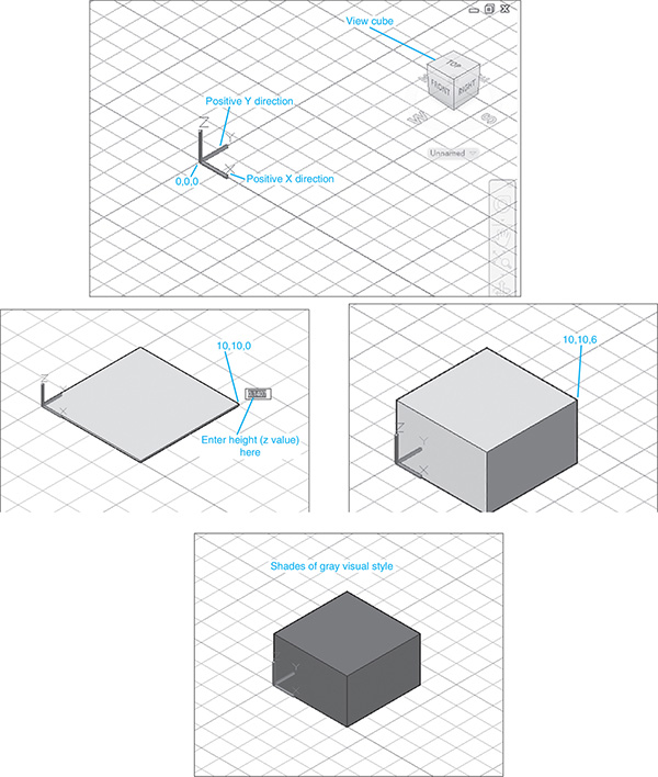
Figure 15-2
To Change the Visual Style
Figure 15-2 shows the box using the conceptual visual styles. The Visual Styles Manager is located under the Visualize tab and on the View panel under the Home tab. See Figure 15-3. To change the visual style of an object, click on the desired new style.
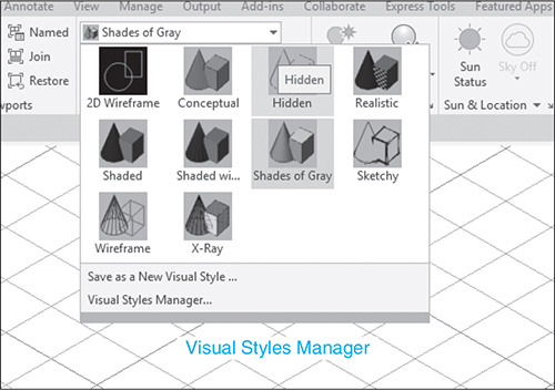
Figure 15-3
To Draw a Box from Given Dimensions
See Figure 15-4. Draw a box with a length of 10, a width of 8, and a height of 4, with its corner at the 2,2,0 point. Use the SE Isometric view orientation.

Figure 15-4
- Select the Box tool from the Modeling panel.
Command: _box
Specify corner or [Center]:
- Type 2,2,0; press Enter.
Specify corner or [Cube Length]:
There are three different ways to define the next point for the box: Enter coordinate values (10,0); activate the Snap command, and use the dynamic screen coordinate display to select the point; or activate the Ortho (F8) command, and enter a length value, as will be defined in this example.
- Type L, and click the Ortho button at the bottom of the screen. Move the cursor to the positive X direction; press Enter.
Specify length:
- Type 10; press Enter.
Specify width:
 Move the cursor to the positive Y direction, and type 8; press Enter.
Specify height:
 Move the cursor to a positive Z direction, and type 4; press Enter.
To Draw a Cube (See Figure 15-5.)
- Select the Box tool from the Modeling panel.
Command: _box
Specify corner of [Center]:

Figure 15-5
- Type 0,0,0; press Enter.
Specify corner or [Cube Length]:
- Type c; press Enter.
Specify length:
- Type 7.5; press Enter.
AutoCAD automatically makes all three edges of the box equal lengths of 7.5.
Note
Use the Ortho tool to align the edge of the cube with the X axis.
To Use Dynamic Grips
This example will use the 7.5 × 7.5 × 7.5 cube just drawn.
- Click any part of the box.
Blue arrowheads will appear on the XY plane of the box. See Figure 15-6.
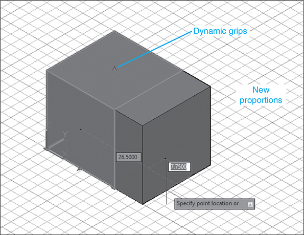
Figure 15-6
- Click and hold one of the arrowheads, and drag the cursor away from the box.
Note how the box changes shape. Try moving different arrows to see how the cube responds. Click the mouse to establish a new edge location.
15-3 Sphere
To Draw a Sphere (See Figure 15-7.)
- Select the Sphere tool. The Sphere tool is a flyout from the Box tool on the Modeling panel under the Home tab.
Specify center of sphere or [3P 2P Ttr]:
- Type 5,5,0; press Enter.
Specify radius or [Diameter]:
- Type 4; press Enter.
The sphere shown in Figure 15-7 uses the Shades of Gray visual style.

Figure 15-7
15-4 Cylinder
There are two options associated with the Cylinder command: circular and elliptical. This means that cylinders may be drawn with either elliptical or circular base planes. The base elliptical shape is drawn by the same procedure as was outlined for the Ellipse command in Chapter 2.
To Draw a Cylinder with a Circular Base
The Cylinder tool is a flyout from the Box tool. See Figure 15-8.

Figure 15-8
- Select the Cylinder tool from the Modeling panel under the Home tab.
Command: _cylinder
Specify center point or base or [3P 2P Ttr Elliptical] <0,0,0>:
- Click a random screen point.
Specify base radius or [Diameter]:
- Move the cursor away from the center point, and select a point to define the cylinder’s diameter.
Specify height or [2 Point/Axis endpoint] <0,0000>:
- Move the cursor upward, and define the cylinder’s height.
To Draw a Cylinder with an Elliptical Base
See Figure 15-9. The sequence that follows uses coordinate value input. The same points could have been selected by moving the crosshairs and pressing the left mouse button.

Figure 15-9
- Select the Cylinder tool from the Modeling panel.
Command: _cylinder
Specify center point or base or [3P 2P Ttr Elliptical] <0,0,0>:
- Type e; press Enter.
Specify endpoint of first axis or [center]:
- Type 0,0,0; press Enter.
This input locates one end of the base axis on the 0,0,0 point of the XY plane.
Specify other endpoint of first axis:
- Type 10,0,0; press Enter.
This input locates the axis line along the X axis. Use the Ortho tool if necessary.
Specify endpoint of second axis:
Note that the line dragging from the crosshairs has one end centered on the axis just defined.
- Type 5,3.5,0; press Enter.
Specify height or [2 Point Axis endpoint]:
- Type 4; press Enter.
An elliptical base can also be defined by first defining a center point for the ellipse and then defining the length of the radii of the major and minor axes.
15-5 Cone
There are two options associated with the Cone tool: circular and elliptical. This means that cones can be drawn with either an elliptical or circular base plane. The base elliptical shape is drawn by the same procedure as was outlined for the Ellipse command in Chapter 2.
To Draw a Cone with an Elliptical Base (See Figure 15-10.)

Figure 15-10
- Select the Cone tool from the Modeling panel under the Home tab.
Command: _cone
Specify center point or base or [3P 2P Ttr Elliptical] <0,0,0>:
- Type e; press Enter.
Specify endpoint of first axis or [Center]:
- Pick a random point.
Specify other endpoint of first axis:
- Move the cursor away from the center point, and select a second point.
Specify endpoint of second axis:
- Move the cursor, creating an elliptical shape, and pick a point.
Specify height or [2 Point Axis endpoint Top radius]:
- Move the cursor to the positive Z direction, and select a point; press Enter.
A response of A to the Apex/<Height>: prompt allows you to define the height of the cone by using numerical values.
To Draw a Cone with a Circular Base (See Figure 15-11.)
- Select the Cone tool from under the Box tool on the Modeling panel.
Command: _conee
Specify center point [3P 2P Ttr Elliptical] <0,0,0>:
- Type 5,5,0; press Enter.
Specify base radius or [Diameter]:
- Type 3; press Enter.
Specify height or [2 Point Axis endpoint Top radius]:
- Move the cursor to the positive Z direction, and type 7; press Enter.

Figure 15-11
Figure 15-12 shows a cone with a top radius of 2.00 and height of 5.00. To create a top radius on the cone, type T in response to the Specify height prompt, and enter a radius value.

Figure 15-12
15-6 Wedge
There are two options associated with the Wedge command: center and corner.
To Draw a Wedge by Defining Its Corner Point (See Figure 15-13.)

Figure 15-13
- Select the Wedge tool from the Modeling panel.
Command: _wedge
Specify first corner or [Center]:
- Type 0,0,0; press Enter.
This input will locate the corner of the wedge on the 0,0,0 point of the XY plane.
Specify other corner or [Cube Length]:
The default response to this command defines the diagonal corner of the wedge’s base.
- Type 10,10,0; press Enter.
Specify height:
- Locate the cursor in the positive Z direction, and type 4; press Enter.
A wedge shape can be drawn by using random points.
To Draw a Wedge by Defining Its Center Point (See Figure 15-14.)
- Select the Wedge tool from the Modeling panel.
Command: _wedge
Specify first corner or [Center] <0,0,0>

Figure 15-14
- Type c; press Enter.
Specify center:
- Type 5,5,0; press Enter.
Specify corner or [Cube Length]:
- Type 10,10,0; press Enter.
Specify height or [2 Point] <4.000>:
- Locate the cursor in the positive Z direction, and type 4; press Enter.
The wedge shown in Figure 15-14 is centered about the XY plane—that is, part of the wedge is above the plane and part is below. This is not easy to see even with the grid shown. The far right corner of the wedge is actually located below the grid at the 10,10 point on the XY plane. Figure 15-14 also shows a side view of the same wedge. Note how the line bisects the height line of the wedge.
To Align a Wedge with an Existing Wedge
This example illustrates how you can use different inputs to position a wedge. Figure 15-15 shows a 10 × 8 × 4 wedge. The problem is to draw another wedge with its back surface aligned with the back surface of the existing wedge.

Figure 15-15
- Select the Wedge tool from the Modeling panel.
Command: _wedge
Specify first corner or [Center]:
- Type 0,0,0; press Enter.
Specify other corner or [Cube Length]:
- Specify length. Type L; press Enter.
Move the cursor so that it is located in the negative X direction.
- Type = –10; press Enter.
Specify width:
- Move the cursor so that it is located in a positive Y direction. Type 8.00; press Enter.
Specify height or [2 Point] <4.0000>:
- Use Osnap Endpoint, and select the Z-axis corner point of the existing wedge.
See Figure 15-16. The model could also have been constructed by using the Copy command to create a second wedge, the Rotate command to rotate the new wedge 180°, and the Move command to align the wedge with the existing wedge. Use Osnap Endpoint to ensure exact alignment.
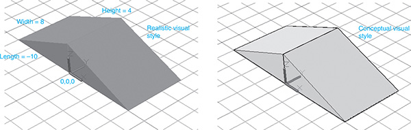
Figure 15-16
15-7 Torus
A torus is a donutlike shape. See Figure 15-17.

Figure 15-17
To Draw a Torus
- Select the Torus tool from the Modeling panel.
Command: _torus
Specify center point or [3P 2P Ttr]:
- Type 0,0,0; press Enter.
This input will locate the center of the torus at the 0,0,0 point on the XY plane.
Specify radius or [Diameter] <3.0000>:
- Type 5; press Enter.
Specify tube radius or [2 Point Diameter]:
- Type 1.5; press Enter.
The finished torus is shown in Figure 15-17.
15-8 Extrude
The Extrude command is used to extend existing 2D shapes into 3D shapes. The Extrude tool can be applied only to a polyline.
To Extrude a 2D Polyline
Figure 15-18 shows a circumscribed hexagon drawn by using the Polygon command located on the Draw panel under the Home tab, centered about the origin. All shapes drawn by use of the Polygon command are automatically drawn as a polyline, so the hexagon can be extruded. How to draw a polygon is discussed in Chapter 2.

Figure 15-18
- Draw a hexagon, a six-sided polygon; select the Extrude tool from the Modeling panel.
Command: _extrude
Select objects to extrude:
- Select the hexagon.
Select objects:
- Press Enter.
Specify height of extrusion or [Direction Path Taper angle] <4.0000>:
- Locate the cursor in a positive Z direction, and then type 6; press Enter.
The dynamic mode will automatically be activated and can be used to approximate the extrusion’s height.
Specify angle of taper for extrusion <0>:
- Press Enter.
Figure 15-19 shows a closed spline created by using Polyline, the Fit option on the Polyline Edit tool. The Extrude command was applied specifying a height of 5.

Figure 15-19
To Create a Polyline from Line Segments
Figure 15-20 shows a 2D shape that was created by using the Line tool from the Draw panel. The object must be converted to a polyline before it can be extruded. For visual purposes, the shape was windowed.

Figure 15-20
- Select the Edit Polyline tool from the Modify panel under the Home tab on the 3D Modeling Workspace.
Select polyline or [Multiple]:
- Select any one of the lines in the 2D shape.
Object selected is not a polyline
Do you want to turn it into one? <Y>:
- Press Enter.
Enter an option [Close Join Width Edit vertex Fit Spline Decurve
Ltype gen Undo]:
- Select the Join option.
The polyline will be defined by joining together all of the line segments to form a polyline. A curve is considered to be a line segment.
Select objects:
- Window the entire object.
Enter an option [Close Join Width Edit vertex Fit Spline Decurve
Ltype gen Undo]:
- Right-click twice; press Enter.
 Select the Extrude tool from the Modeling panel, and create an extrusion 5 units high.
15-9 Revolve
The Revolve tool on the Modeling panel is used to create a solid 3D object by rotating a 2D shape around an axis of revolution. Figure 15-21 shows a torus created by rotating a circle around a straight line.

Figure 15-21
To Create a Revolved Solid Object
This procedure assumes that the curve path (2D shape) and the line that will be used as the axis of revolution already exist on the drawing.
- Select the Revolve tool from the Modeling panel.
Command: _revolve
Select objects to revolve:
- Select the circle.
Select objects to revolve:
- Press Enter.
Specify start point for axis of revolution or define axis by [Object
X Y Z] <object>:
- Select one end of the line to be used as the axis of revolution. Use Osnap Endpoint if necessary.
Specify axis endpoint:
- Select the other end of the axis line.
Specify angle of revolution or [Start angle] <360>:
- Press Enter.
15-10 Helix
See Figure 15-22.

Figure 15-22
- Type helix in response to a command prompt.
Number of turns = 3, Twist = CCW.
Specify center point of base:
In this example, the origin (0,0,0) was selected.
- Select (WAS) a point (Now) the 0,0,0 origin.
Specify base radius or [Diameter] <1.0000>:
- Type 2; press Enter.
Specify top radius or [Diameter] <2.0000>:
- Press Enter.
Specify helix height or [Axis endpoint Turns turn Height tWist]
<6.3885>:
- Type t; press Enter.
Enter number of turns <3.0000>:
- Type 8; press Enter.
Specify helix height or [Axis endpoint Turns turn Height tWist]
<1.0000>:
- Use the dynamic input option, and select a helix height by moving the cursor or by entering a number.
 Press the left mouse button.
15-11 Polysolid
See Figures 15-23 and 15-24.
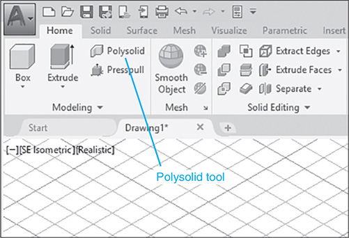
Figure 15-23

Figure 15-24
The Polysolid tool assumes a 2D shape already exist on the drawing.
- Select the Polysolid tool from Modeling panel under the Home tab.
Polysolid Specify start point or [Object Height Width Justified] <ob
ject>:
- Type 0,0,0; press Enter.
Specify next point or [Arc Close Undo]:
- Position the cursor in the positive X direction, and then type 10; press Enter.
Note
Turn the Ortho command on to align the polysolid with the X axis.
Specify next point or [Arc Undo]:
- Position the cursor in the positive Y direction, and then type 8; press Enter.
Specify next point or [Arc Close Undo]:
Turn the Ortho command off.
- Type a; press Enter.
The polysolid will now generate an arc.
- Create an arc, press the right mouse button, and select the Enter option.
15-12 Loft
See Figure 15-25.

Figure 15-25
- Use the Circle tool on the Draw panel, and draw a ø10 circle centered about the 0,0,0 origin.
- Use the Circle tool on the Draw panel to draw a ø5 circle centered about 0,0,12.
The Z value of 12 will locate the ø5 circle’s center point above the ø10 circle’s center point.
- Select the Loft tool from the Solid panel under the Solid tab.
Select the cross sections in lofting order:
- Select the ø10 circle.
Select the cross sections in lofting order:
- Select the ø5 circle.
Select the cross sections in lofting order:
- Press the right mouse button.
- Select the Enter option.
15-13 Intersect
The Intersect command is used to define a volume common to two or more existing solid objects. Figure 15-26 shows a ø12 × 6 cylinder centered about the 0,0,0 point and a 20 × 20 × 5 box with one of its corners located on the 0,0,0 point. They were both drawn on the XY plane. The following procedure will define the volume common to both of them:
- Select the Intersect tool from the Solid Editing panel under the Home tab.
Command: _intersect
Select objects:
- Select the box.
Select objects:
- Select the cylinder.
Select objects:
- Press Enter.
Figure 15-26 shows the resulting common volume.
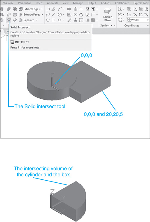
Figure 15-26
15-14 Union and Subtract
Solid objects may be combined to form more complex objects. Objects can be added together by the Union command and subtracted from each other by the Subtract command. A volume common to two or more objects may be defined by the Intersect command. The tools for these three commands are located on the Solid Editing panel under the Home tab in the 3D Modeling workspace, and on the Edit panel under the Home tab in the 3D Basics workspace. This section will use the 3D Basics workspace. See Figure 15-27.

Figure 15-27
To access the 3D Basics workspace click the Workspace Switching tool located on the ribbon at the bottom of the drawing screen.
To Union Two Objects
Figure 15-28 shows two 10 × 10 × 3 solid boxes drawn with adjoining surfaces. Both are drawn using the Conceptual visual style.

Figure 15-28
- Select the Union tool from the Edit panel.
Command: _union
Select objects:
- Select a box.
Select objects:
- Select the other box.
Select objects:
- Press Enter.
Note the changes in the boxes after they have been unioned. The solid object is no longer two boxes, but an L-shaped object.
To Subtract an Object
Figure 15-29 shows the L-shaped bracket formed in Figure 15-28. This exercise will add a hole to the front surface. Holes are created in solid objects by subtracting solid cylinders from the existing objects.
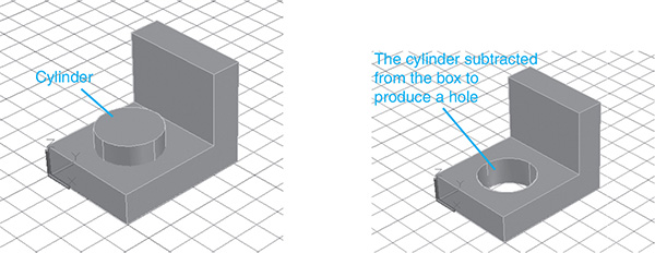
Figure 15-29
Remember, we are using the 3D Basics workspace.
- Select the Cylinder tool from the Create panel. The Cylinder tool is a flyout from the Box tool.
Command: _cylinder
Specify center point of base or [3P 2P Ttr Elliptical]:
- Type 5,5,0; press Enter.
Remember, we are still working on the XY plane.
Specify base radius or [2 Point Axis endpoint] <5.0000>:
- Type 3; press Enter.
Specify height or [2 Point Axis endpoint] <10.0000>:
- Type 5; press Enter.
The height of the cylinder was deliberately drawn higher than the top surface of the bracket to illustrate that the two heights need not be equal for the Subtract command to work. The only requirement is that the cylinder be equal to, or greater than, the height of the box surface. See Figure 15-29.
- Select the Subtract tool from the Edit panel.
Command: _subtract
Select solids and regions to subtract from . . .
Select objects:
This prompt is asking you to define the main object—that is, the object that you want to remain after the subtraction.
- Select the L-shaped bracket.
Select objects:
- Press Enter.
Select solids and regions to subtract . . .
Select objects:
This prompt is asking you to define the object that you want removed by the subtraction.
- Select the cylinder.
Select objects:
 Press Enter.
15-15 Solid Modeling and UCSs
In this section, we will again work with the L-shaped bracket and add a hole to the upper surface. The procedure is to create a new UCS with its origin at the left intersection of the two perpendicular surfaces, and then create and subtract a cylinder. See Figure 15-30.

Figure 15-30
- Select the 3-Point tool from the Coordinates panel under the Home tab on the 3D Basics.
Specify new origin point <0.0000>:
- Use Osnap Endpoint (<shift>/right button), and select the corner as shown.
The coordinate system will move to the new location.
UCS Specify point on positive portion of X = Axis <1.0000, 0.0000,
0,0000>:
- Use the Osnap Endpoint tool, and select the corner, as shown.
UCS Specify point on positive −1 portion of the USC XY plan <1.0000,
0.0000, 0.0000>:
- Use the Osnap Endpoint tool, and select the corner, as shown.
- Select the Cylinder tool from the Create panel.
Specify center point of the base or [3P 2P Ttr Elliptical]:
- Type 5,3.5,0; press Enter.
We are now drawing on the new UCS.
Specify base radius or [Diameter] <1.5000>:
- Type 2.50; press Enter.
Specify height or [2 Point Axis endpoint] <5.0000>:
- Use the dynamic input options, and move the cursor in the negative Z direction.
The cylinder height will increase as the cursor is moved.
- Define the cylinder height at any distance greater than 3, the thickness of the L-bracket; press Enter.
See Figure 15-31.

Figure 15-31
 Select the Subtract tool from the Edit panel.
Command: _subtract
Select solids and regions to subtract from . . .
Select objects:
 Select the L-shaped bracket.
Select objects:
 Press Enter.
Select solids and regions to subtract . . .
Select objects:
 Select the cylinder.
Select objects:
 Press Enter.
 Click the World tool on the Coordinates panel under the Home tab.
Figure 15-32 shows the resulting solid object.

Figure 15-32
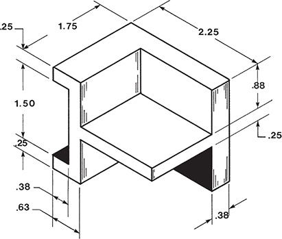
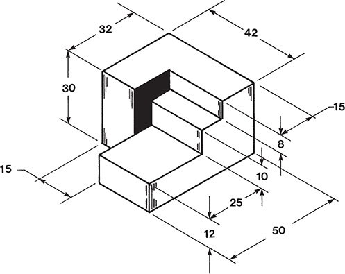
15-16 Combining Solid Objects
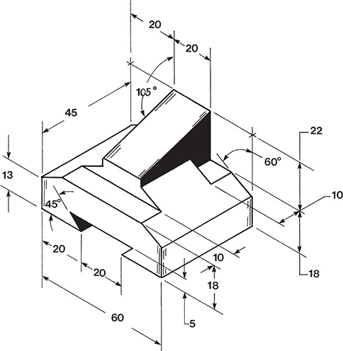
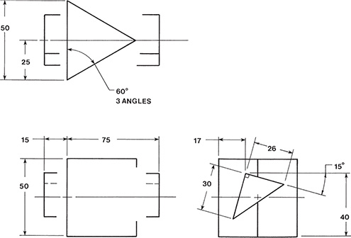
Figure 15-33 shows a dimensioned object. The following section explains how to create the object as a solid model. There are many different ways to create a solid model. The sequence presented here was selected to demonstrate several different input options.

Figure 15-33
To Set Up the Drawing
Set up the drawing as follows:
Acadiso3D template
Units = Decimal (millimeters)
Drawing Limits = 297,210
Grid = 10 × 10 parallel
Snap = 5
View = SE Isometric
The object is relatively small, so use the mouse wheel or the Zoom tool to create a size that you find visually comfortable.
To Draw the First Box
The size specifications for this box are based on the given dimensions.
- Select the Box tool from the Create panel. (Use the 3D Basics workspace.)
Command: _box
Specify first corner or [Center]:
- Select the 0,0,0 point on the WCS by pressing Enter.
Specify other or [Cube Length]:
- Type L; press Enter.
Specify length:
- Locate the cursor on the positive X axis, and type 80; press Enter.
Turn Ortho on, if needed.
Specify width:
- Locate the cursor in the positive Y direction, and type 36; press Enter.
Specify height:
- Locate the cursor in the positive Z direction, and type 30; press Enter.
See Figure 15-34.

Figure 15-34
To Create the Internal Open Volume
The volume will be created by subtracting a second box from the first box.
- Select the Box tool from the Create panel.
Command: _box
Specify corner of box or [Center]:
- Select the 0,10,0 point on the WCS.
The point 0,10,0 was selected on the basis of the given 10-millimeter dimension. The point can be selected by using the crosshairs because it is on the grid located on the XY plane.
Specify corner or [Cube Length]:
- Type L; press Enter.
Specify length:
- Locate the cursor in the positive X direction, and type 80; press Enter.
Specify width:
- Locate the cursor in the positive Y direction, and type 15; press Enter.
Specify height:
- Locate the cursor in the positive Z direction, and type 20; press Enter.
Figure 15-35 shows the second box within the first box.

Figure 15-35
- Select the Subtract tool from the Edit panel.
Command: _subtract
Select solids and regions to subtract from . . .
Select objects:
- Select the first box.
Select objects:
- Press Enter.
Select solids and regions to subtract . . .
Select objects:
- Press Enter.
See Figure 15-36.

Figure 15-36
To Create the Top Cutout
See Figure 15-37.

Figure 15-37
The cutout will be created by drawing a box and wedge and subtracting them from the existing object.
To Create a Box
- Move the origin to the top surface of the box, using the 3-Point tool located on the Coordinates panel. Define the origin, second point, and third point, as shown. Use the Endpoint option of the Osnap tool to define the point.
- Select the Box tool from the Create panel.
Specify first corner or [Center]:
- Type 20,0,0; press Enter.
Specify other corner or [Cube Length]:
- Position the cursor in the positive X and Y directions, and type 60,35,0; press Enter.
Specify height or [2 Point]<0.0000>:
- Position the cursor in the negative Z direction, and type –5; press Enter.
- Use the Subtract tool from the Edit panel, and subtract the box from the existing object.
See Figure 15-38.

Figure 15-38
To Create a Wedge
See Figure 15-39.

Figure 15-39
- Define a new UCS, as shown. Use the 3-Point tool, or use the Origin tool located on the Coordinates panel in the 3D Modeling workspace.
- Select the Z tool from the Coordinates panel, and rotate the axis 90° around the Z axis.
See Figure 15-40.

Figure 15-40
- Select the Wedge tool from the Create panel.
Specify first corner or (Center):
- Select the 0,0,0 point of the current UCS.
Specify other corner or [Cube Length]:
- Use Osnap Endpoint, and select the opposite diagonal corner of the box cutout, as shown.
Specify height or [2 Point]<0.0000>:
- Locate the cursor in the negative Z direction, and type –20; press Enter.
See Figure 15-41.

Figure 15-41
- Subtract the wedge from the existing object.
- Use the World tool from the Coordinates panel, and return the axis system to the original location.
See Figure 15-42.

Figure 15-42
15-17 Intersecting Solids
Figure 15-43 shows an incomplete 3D drawing of a cone and a cylinder. The problem is to complete the drawing in 3D and show the front, top, and right-side orthographic views of the intersecting objects.

Figure 15-43
To Set Up the Drawing
Set up the drawing screen as follows:
Grid = 0.50 × 0.50
Snap = .25
Units = Decimal
View = SE Isometric
Template = acad3D
3D Modeling workspace
See Figure 15-44. The objects are small, so use the mouse wheel or the Zoom command to create a comfortable visual size.

Figure 15-44
To Draw the Cone
- Select the Cone tool from the Modeling panel under the Home tab in the 3D Modeling workspace.
Command: _cone
Specify center point of base or [3P 2P Ttr Elliptical]
- Type 0,0,0; press Enter.
The center point of the cone will be located on the origin of the WCS.
Specify base radius or [Diameter] <0,0000>:
- Type d; press Enter.
Specify diameter:
- Type 1.50.
Specify height or [2 Point Axis endpoint Top radius]<1.0000>:
- Locate the cursor in the positive Z direction, and type 2.50; press Enter.
See Figure 15-45.

Figure 15-45
- Select the Visual Styles tool from the View panel, and change the style to Conceptual.
To Draw the Cylinder
- Select the Origin UCS tool from the Coordinates panel on the 3D Modeling workspace.
Command: _ucs
Specify new origin point <0,0,0>:
To change workspaces, click the Workspace Switching tool on the ribbon at the bottom of the drawing screen, and select the 3D Modeling workspace.
- Type 1.25,0,0; press Enter.
This input locates the origin in the same plane as the end of the cylinder. See Figure 15-46.
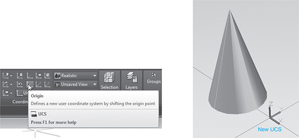
Figure 15-46
- Select the X Axis Rotate UCS tool from the Coordinates panel, and press Enter, accepting the 90° default value. Then select the Y Axis Rotate UCS tool, type –90, and press Enter.
See Figure 15-46.
- Select the Cylinder tool from the Modeling panel under the Home tab.
Command: _cylinder
Specify center point of base or [3P 2P Elliptical]:
- Type 0, .88, 0
Specify base radius or [Diameter] <0.0000>:
- Type d; press Enter.
Specify diameter <1.0000>:
- Type .63; press Enter.
Specify height or [2Point Axis endpoint] <1.0000>:
- Locate the cursor in the positive Z direction, and type 2.50; press Enter.
See Figure 15-47.

Figure 15-47
To Complete the 3D Drawing
- Select the Union tool from the Solid Editing panel.
Command: _union
Select objects:
- Select the cone.
Select objects:
- Select the cylinder.
Select objects:
- Press Enter.
Command:
- Select the World tool from the Coordinates panel.
- Turn off Grid.
See Figure 15-48.

Figure 15-48
To Create the Viewports for the Orthographic Views
Click the Visualize tab in the 3D Modeling workspace, access the Viewport Configuration panel, and select the Four: Equal option.
See Figure 15-49. AutoCAD will automatically create three orthographic views of the object, plus an isometric view. See Figure 15-50. These views may be modified, as explained in Section 14-13, to show a front, top, and right-side orthographic view of the object.

Figure 15-49

Figure 15-50
15-18 Solid Models of Castings
Figure 15-51 shows a casting. Note that the object includes rounded edges. These rounded edges can be created on a solid model by using the Fillet command. The Fillet command was explained in Chapter 2.

Figure 15-51
Decimal inches are used for all dimensions.
To Draw the Basic Shape
The basic shape will first be drawn in 2D, then extruded into the 3D solid model.
- Set up the drawing screen as needed.
In this example, the acad3D template was used, and a top view was created by clicking the word Top on the View cube.
- Draw the basic shape by using first the Circle tool, and then the Line tool along with the Osnap Tangent (<Ctrl>, right mouse button) option.
See Figure 15-52. It is important to know the center point locations for the two circles in terms of their X,Y components. In this example, the center point location for the large circle is 0,0, and the location for the small circle is 4,0. The large circle’s diameter equals 3.00 inches, and the small circle’s diameter equals 1.25 inches. The circles are 4.0 inches apart.

Figure 15-52
To Create a Polyline from the Basic Shape
Because only polylines can be extruded, some of the lines in the basic shape must be formed into a polyline. The large circle can be extruded, so it need not be included as part of the polyline; however, the polyline must be a closed area, so it will need part of the circle. The needed circular segment can be created by drawing a second large circle directly over the existing circle and then using the Trim command to remove the excess portion. Remember that two lines can occupy the same space in AutoCAD drawings. If there is difficulty in working with the two large circles, trim the circles and then add another larger circle, if needed.
Figure 15-53 shows the resulting shape that will be joined to form a polyline.

Figure 15-53
- Select the Edit Polyline tool from the Modify panel.
Command: _pedit
Select polyline or [Multiple]:
- Select the remaining portion of the small circle.
Object selected is not a polyline
Do you want to turn it into one? <Y>
- Press Enter.
Enter an option [Close Join Width Edit vertex Fit/Spline Decurve
Ltype gen Undo eXit] <X>:
- Select the Join option; press Enter.
Select objects:
- Window the object; press Enter.
Select objects:
- Press Enter twice.
There will be no visible changes to the lines, but they have been combined to form a single polyline.
To Extrude the Shape
- Select the SE Isometric tool from the Visualize panel under the View tab, and make it the current view.
- Use the Zoom tool, if needed, to present the figure at a comfortable visual size.
See Figure 15-54.

Figure 15-54
- Select the Extrude tool from the Modeling panel under the Home tab.
Command: _extrude
Select objects to extrude:
- Select the polyline.
In this example, a height of 1.00 was assigned. See Figure 15-55.
Command:

Figure 15-55
The shape is presented in the Conceptual visual style.
- Select the Cylinder tool from the Modeling panel under the Home tab, and create a cylinder whose diameter equals the original large-circle diameter (ø3.00) and whose height is 3, with a center point of 0,0,0.
See Figure 15-56.

Figure 15-56
To Add the Holes
Create the holes by subtracting cylinders from the object.
- Select the Cylinder tool from the Modeling panel under the Home tab.
Command: _cylinder
Specify center point for base of cylinder or [Elliptical] <0,0,0>:
- Type 0,0,0; press Enter.
This value came from the original circle’s center point location.
- Enter the appropriate diameter and height values. In this example, a radius of 0.50 inch and a height of 3.5 were selected.
Command:
- Repeat the Cylinder command.
Specify center point for base of cylinder or [Elliptical] <0,0,0>:
- Type 4,0,0.
- Draw a ø1.00 × 1.25 cylinder.
See Figure 15-57.

Figure 15-57
- Select the Union tool from the Solid Editing panel, and join the large cylinder portion of the object to the polyline portion.
- Select the Subtract tool from the Solid Editing panel, and subtract the cylinders from the basic shape.
See Figure 15-58.

Figure 15-58
To Create the Rounded Edges
- Select the Fillet tool from the Modify panel in the 3D Modeling workspace.
Command: _fillet
Current settings: Mode = TRIM, Radius = 0.5000.
Select first object or [Undo Polyline Radius Trim Multiple]:
- Type r, and enter a value of .125.
- Repeat the Fillet command, and select the outside edge of the top surface of the large cylindrical portion of the object.
Enter fillet radius <0.1250>:
- Press Enter.
Select first object or [Undo Polyline Radius Trim Multiple]:
- Press Enter.
See Figure 15-59.

Figure 15-59
- Use the Fillet tool to create a fillet along the top edges of the object as shown in Figure 15-60.
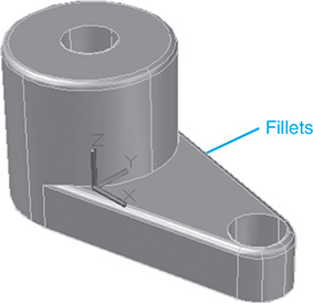
Figure 15-60
Note that the arc edge line between the large cylindrical portion of the object and the extended flat area cannot be filleted.
15-19 Thread Representations in Solid Models
This section explains how to draw thread representations for solid models. The procedure presented only broadly represents a thread. It is not an actual detailed solid drawing of a thread. As with the thread representations presented in Chapter 11 for 2D drawings, 3D representations are acceptable for most applications.
- Select the Cylinder tool from the Modeling panel under the Home tab, and draw a cylinder.
In the example shown, a cylinder of diameter 3 and a height of 6 was drawn centered about the 0,0,0 point of the WCS. See Figure 15-61. It is presented on the acad3D template with a Wireframe visual style.

Figure 15-61
- Draw a circle with a diameter equal to the diameter of the cylinder. In this example, use ø3.00.
- Select the 3D Array command from the Modify panel, located under the Home tab. The 3D Array tool is a flyout from the 3D Mirror tool.
Select object:
- Select the circle; press Enter.
Enter the type of array [Rectangular or Polar array] <e>:
- Type r; press Enter.
Enter the number of rows (---) <1>:
- Press Enter.
Enter the number of columns: (|||) <1>:
- Press Enter.
Enter the number of levels:
- Type 11; press Enter.
The number 11 is used because the cylinder is 6 units high, and in this example circles representing threads will be spaced 0.5 apart. The top edge of the thread will be chamfered.
Specify the distance between levels: (. . .):
- Type .5; press Enter.
- Select the Move tool from the Modify panel, and move the arrayed circles’ center points to the 0,0,0 origin.
- Select the Chamfer tool from the Modify panel, and draw a .5 × .5 chamfer around the top edge of the cylinder.
15-20 List
The List command is used to display database information for a drawn solid object. Figure 15-62 shows a list for the cone-cylinder object shown in Figure 15-48. There is no icon for the List command. Type list in response to a command prompt, and select the object.

Figure 15-62
15-21 Massprop
The Massprop command is used to display information about the structural characteristics of an object. Figure 15-63 shows the Massprop information for the object shown in Figure 15-48. To access the Massprop command, type Massprop in response to a command prompt, and select the object.

Figure 15-63
15-22 Face and Edge Editing
AutoCAD has the capability to edit faces and edges of existing solids. The Solid Editing commands are located on the Solid Editing panel under the Home tab in the 3D Modeling workspace. See Figure 15-64. The following examples are based on a solid box of dimensions 4 × 2 × 3 drawn in the Shaded with edges visual style:

Figure 15-64
To Extrude a Face (See Figure 15-65.)

Figure 15-65
- Select the Extrude Faces tool from the Solid Editing panel on the 3D Modeling workspace.
Select faces or [Undo Remove]:
- Select the right face by moving the cursor to the center of the face and left-clicking.
Select faces or [Undo Remove]:
- Press the right mouse button, and enter the face.
Specify height of extrusion or [Path]:
- Type 2; press Enter.
Specify angle of taper for extrusion <0>:
- Press Enter.
- Select the eXit option or a new command.
To Extrude a Face Along a Path
See Figure 15-66. A line has been drawn from the right corner of the box 3″, 30°. This line will serve as the extrusion path.

Figure 15-66
- Select the Extrude Faces tool from the Solid Editing panel.
Select faces or [Undo Remove]:
- Click the right face.
Select faces or [Undo Remove]:
- Press the right mouse button, and enter the face.
Specify height of extrusion or [Path]:
- Type p; press Enter.
Select extrusion path:
- Select the line.
- Select the eXit option or a new command.
A second set of options will appear under the same heading.
- Select the eXit option or a new command.
To Extrude Two Faces at the Same Time (See Figure 15-67.)

Figure 15-67
- Select the Extrude Faces tool from the Solid Editing panel.
Select faces or [Undo Remove]:
- Select the right face, and then select the top face.
Select faces or [Undo Remove]:
- Press the right mouse button, and enter the face.
Specify height of extrusion or [Path]:
- Type 2; press Enter.
- Select the eXit option or a new command.
A second set of options will appear under the same heading.
- Select the eXit option or a new command.
To Move a Face (See Figure 15-68.)

Figure 15-68
- Select the Move Faces tool from the Solid Editing panel.
Select faces or [Undo Remove]:
- Select the right face, and enter it.
Specify a base point or displacement:
- Select the corner of the box as shown.
Use the Endpoint option of the Object snap toolbar.
Specify a second point of displacement:
- Select a second point along the X axis.
- Press Enter.
- Select the eXit option or a new command.
A second set of options will appear under the same heading.
- Select the eXit option or a new command.
To Offset Faces (See Figure 15-69.)

Figure 15-69
- Select the Offset Faces tool from the Solid Editing panel.
Select faces or [Undo Remove]:
- Select the right and front faces, and enter them.
Specify the offset distance:
- Type 1.5; press Enter.
- Select the eXit option or a new command.
A second set of options will appear under the same heading.
- Select the eXit option or a new command.
To Rotate a Face (See Figure 15-70.)

Figure 15-70
- Select the Rotate Faces tool from the Solid Editing panel.
Select faces or [Undo Remove]:
- Select the front face, and enter it.
Specify an axis point or [Axis by object View Xaxis Yaxis Zaxis]
<2 points>:
- Type x; press Enter.
Specify the origin of the rotation <0,0,0>:
- Press Enter.
Specify the rotation angle or [Reference]:
- Type 15; press Enter.
An input of –15 would have rotated the face in the opposite direction.
- Select the eXit option or a new command.
A second set of options will appear under the same heading.
- Select the eXit option or a new command.
To Taper a Face
See Figure 15-71.

Figure 15-71
- Select the Taper Faces tool from the Solid Editing panel.
Select faces or [Undo Remove]:
- Select the right front face.
Select faces or [Undo Remove]:
- Press the right mouse button, and enter the face.
Specify the base point:
- Select the lower left corner of the box.
Specify another point along the axis of tapering:
- Use Osnap Endpoint, and specify the top corner, as shown in Figure 15-74.
Specify the taper angle:
- Type 30; press Enter.
[Extrude Move Rotate Offset Taper Delete Copy coLor Undo eXit]<eXit>:
- Select the eXit option or a new command.
A second set of options will appear under the same heading.
- Select the eXit option or a new command.
To Copy a Face
See Figure 15-72.

Figure 15-72
- Select the Copy Faces tool from the Solid Editing panel.
Select faces or [Undo Remove]:
- Select the right front face.
Select faces or [Undo Remove]:
- Press the right mouse button, and enter the face.
Specify a base point or displacement:
- Select the lower left corner of the box.
Specify a second point of displacement:
- Select the location for the copied face.
[Extrude Move Rotate Offset Taper Delete Copy coLor Undo eXit]<eXit>:
- Select the eXit option or a new command.
A second set of options will appear under the same heading.
- Select the eXit option or a new command.
To Copy Edges (See Figure 15-73.)

Figure 15-73
- Select the Copy Edges tool from the Solid Editing panel.
The Copy Edges is a flyout from the Extract Edges tool on the Solid Editing panel.
Select edges or [Undo Remove]:
- Select two edges.
Select edges or [Undo Remove]:
- Press the right mouse button, and enter the edges.
Specify a base point or displacement:
- Select the lower endpoint of the vertical line.
Specify a second point of displacement:
- Select a second point.
Enter an edge editing option [Copy coLor Undo eXit] <eXit>:
- Type x; press Enter.
To Imprint an Object (See Figure 15-74.)
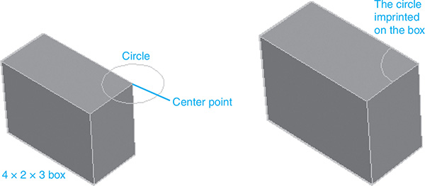
Figure 15-74
- Draw a solid box (4 × 2 × 3), then a ø1.00 circle with its center point on the upper right corner of the box, as shown.
- Select the Imprint tool from the Solid Editing panel.
The Imprint tool is a flyout from the Extract Edges tool.
Select a 3D solid:
- Select the box.
Select an object to imprint:
- Select the circle.
Select the source object <N>:
- Type y; press Enter twice.
15-23 Exercise Problems
Draw the objects in Exercise Problems EX15-1 through EX15-43 as follows:
Draw each as a solid model.
Create front, top, and right-side orthographic views from the solid models.
Dimension the orthographic views.
EX15-1 Inches

EX15-2 Inches

EX15-3 Millimeters

EX15-4 Millimeters

EX15-5 Inches
EX15-6 Millimeters
EX15-7 Millimeters

EX15-8 Millimeters

EX15-9 Inches

EX15-10 Millimeters

EX15-11 Millimeters

EX15-12 Inches

EX15-13 Millimeters

EX15-14 Inches

EX15-15 Millimeters
EX15-16 Millimeters

EX15-17 Inches

EX15-18 Millimeters

EX15-19 Millimeters

EX15-20 Millimeters
EX15-21 Inches

EX15-22 Millimeters

EX15-23 Millimeters

EX15-24 Millimeters

EX15-25 Millimeters

EX15-26 Millimeters (Scale 2:1)

EX15-27 Millimeters

EX15-28 Inches

EX15-29 Millimeters

EX15-30 Inches (Scale 2:1)

EX15-31 Millimeters

EX15-32 Millimeters (Scale 2:1)

EX15-33 Millimeters

EX15-34 Millimeters

EX15-35 Inches (Scale 2:1)

EX15-36 Inches (Scale 4:1)

EX15-37 Inches

EX15-38 Inches

EX15-39 Millimeters

EX15-40 Millimeters
EX15-41 Millimeters

EX15-42 Millimeters

EX15-43 Millimeters

EX15-44 Inches
Draw a solid model of the object, and then create the three indicated sectional views from the model.

EX15-45 Millimeters

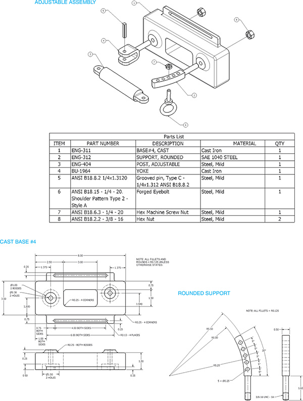
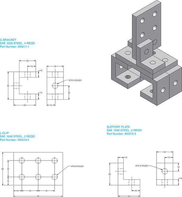
Redraw the assemblies in Exercise Problems EX15-46 through EX15-48 as exploded solid models with the individual parts located in approximately the positions shown.
EX15-46 Millimeters
EX15-47 Millimeters

EX15-48 Millimeters

Prepare solid models and 3D orthographic views of the intersecting objects in Exercise Problems EX15-49 through EX15-54.
EX15-49 Inches

EX15-50 Millimeters

EX15-51 Millimeters
EX15-52 Millimeters

EX15-53 Millimeters

EX15-54 Inches

EX15-55 Millimeters

EX15-56
EX15-57

EX15-58

EX15-59


EX15-60
Design an access controller according to the information given. The controller works by moving an internal cylinder up and down within the base to align with output holes A and B. Liquids will enter the internal cylinder from the top and then exit the base through holes A and B. Include as many holes in the internal cylinder as necessary to create the following liquid exit combinations:
- A open, B closed
- A open, B open
- A closed, B open
The internal cylinder is held in place by an alignment key and a stop button. The stop button is to be spring-loaded so that it will always be held in place. The internal cylinder will be moved by pulling out the stop button, repositioning the cylinder, and then reinserting the stop button.
Prepare the following drawings:
Draw the objects as solid models.
Draw an assembly drawing.
Draw detail drawings of each nonstandard part. Include positional tolerances for all holes.
Prepare a parts list.

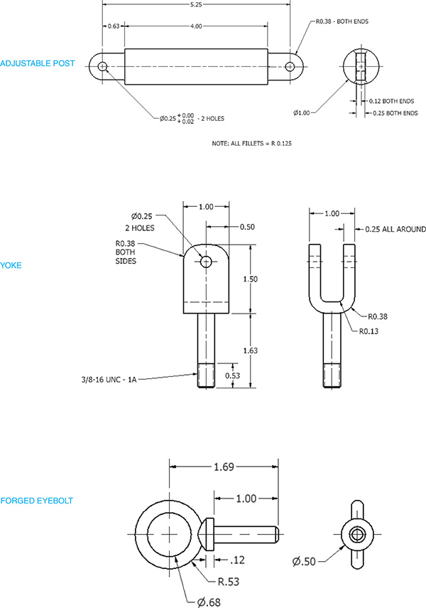
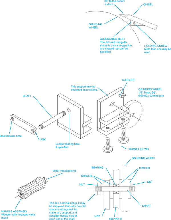
EX15-61
Design a hand-operated grinding wheel specifically for sharpening a chisel. The chisel is to be located on an adjustable rest while it is being sharpened. The mechanism should be able to be clamped to a table during operation by two thumbscrews.
A standard grinding wheel is ø6.00 inch, is ½ inch thick, and has an internal mounting hole with a 50.00 ÷ 0.3 millimeter bore.
Prepare the following drawings:
Draw the objects as solid models.
Draw an assembly drawing.
Draw detail drawings of each nonstandard part.
Prepare a parts list.
EX15-62
Draw an assembly drawing of the given object.
Prepare a parts list.
Select appropriate fasteners to hold the object together.
Define the appropriate tolerances.
EX15-63
Draw an assembly drawing of the given object.
Prepare a parts list.
Select appropriate fasteners to hold the object together.
Define the appropriate tolerances.
Use phantom lines, and define the motion of the center link and the rocker link if the drive link rotates 360°.

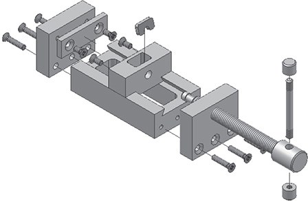
EX15-64
Draw an assembly drawing of the minivise.
Prepare a parts list.
Select the appropriate fasteners to hold the vise together.
Redesign the interface between the drive screw and the holder plate.
Minivise

Minivise-ISO
- BASE
SAE 1040 STEEL

- DRIVE SCREW
SAE 1040 STEEL

- END PLATE
SAE 1040 STEEL

- SLIDER
SAE 1040 STEEL

- HOLDER PLATE
SAE 1040 STEEL

- FACE PLATE
SAE 1040 STEEL

- HANDLE
SAE 1040 STEEL

- END CAP
SAE 1040 STEEL

- DRIVE PLATE
SAE 1040 STEEL

- M5 × 10 RECESSED COUNTERSUNK HEAD-STEEL
- M5 × 22 RECESSED COUNTERSUNK HEAD-STEEL
EX15-65
Create the following for the slider assembly shown:
- Select the appropriate fasteners.
- Create an assembly drawing.
- Create a parts list.
- Specify the tolerance for the guide shaft/bearings interface.

