Chapter 17. IP Routing in the LAN
This chapter covers the following exam topics:
1.0 Network Fundamentals
1.6 Configure and verify IPv4 addressing and subnetting
2.0 Network Access
2.4 Configure and verify (Layer 2/Layer 3) EtherChannel (LACP)
The preceding two chapters showed how to configure an IP address and mask on a router interface, making the router ready to route packets to/from the subnet implied by that address/mask combination. While true and useful, all the examples so far ignored the LAN switches and the possibility of VLANs. In fact, the examples so far show the simplest possible cases: the attached switches as Layer 2 switches, using only one VLAN, with the router configured with one ip address command on its physical interface. This chapter takes a detailed look at how to configure routers so that they route packets to/from the subnets that exist on each and every VLAN.
Because Layer 2 switches do not forward Layer 2 frames between VLANs, a network must use routers to route IP packets between subnets to allow those devices in different VLANs/subnets to communicate. To review, Ethernet defines the concept of a VLAN, while IP defines the concept of an IP subnet, so a VLAN is not equivalent to a subnet. However, the set of devices in one VLAN are typically also in one subnet. By the same reasoning, devices in two different VLANs are normally in two different subnets. For two devices in different VLANs to communicate with each other, routers must connect to the subnets that exist on each VLAN, and then the routers forward IP packets between the devices in those subnets.
This chapter discusses the configuration and verification steps related to three methods of routing between VLANs with three major sections:
VLAN Routing with Router 802.1Q Trunks: The first section discusses how to configure a router to use VLAN trunking as connected to a Layer 2 switch. The router does the routing, with the switch creating the VLANs. The link between the router and switch use trunking so that the router has an interface connected to each VLAN/subnet. This feature is known as routing over a VLAN trunk and also known as router-on-a-stick (ROAS).
VLAN Routing with Layer 3 Switch SVIs: The second section discusses using a LAN switch that supports both Layer 2 switching and Layer 3 routing (called a Layer 3 switch or multilayer switch). To route, the Layer 3 switch configuration uses interfaces called switched virtual interfaces (SVI), which are also called VLAN interfaces.
VLAN Routing with Layer 3 Switch Routed Ports: The third major section of the chapter discusses an alternative to SVIs called routed ports, in which the physical switch ports are made to act like interfaces on a router. This third section also introduces the concept of an EtherChannel as used as a routed port in a feature called Layer 3 EtherChannel.
“Do I Know This Already?” Quiz
Take the quiz (either here or use the PTP software) if you want to use the score to help you decide how much time to spend on this chapter. The letter answers are listed at the bottom of the page following the quiz. Appendix C, found both at the end of the book as well as on the companion website, includes both the answers and explanations. You can also find both answers and explanations in the PTP testing software.
Table 17-1 “Do I Know This Already?” Foundation Topics Section-to-Question Mapping
Foundation Topics Section |
Questions |
|---|---|
VLAN Routing with Router 802.1Q Trunks |
1, 2 |
VLAN Routing with Layer 3 Switch SVIs |
3, 4 |
VLAN Routing with Layer 3 Switch Routed Ports |
5, 6 |
1. Router 1 has a Fast Ethernet interface 0/0 with IP address 10.1.1.1. The interface is connected to a switch. This connection is then migrated to use 802.1Q trunking. Which of the following commands could be part of a valid configuration for Router 1’s Fa0/0 interface? (Choose two answers.)
a. interface fastethernet 0/0.4
b. dot1q enable
c. dot1q enable 4
d. trunking enable
e. trunking enable 4
f. encapsulation dot1q 4
2. Router R1 has a router-on-a-stick (ROAS) configuration with two subinterfaces of interface G0/1: G0/1.1 and G0/1.2. Physical interface G0/1 is currently in a down/down state. The network engineer then configures a shutdown command when in interface configuration mode for G0/1.1 and a no shutdown command when in interface configuration mode for G0/1.2. Which answers are correct about the interface state for the subinterfaces? (Choose two answers.)
a. G0/1.1 will be in a down/down state.
b. G0/1.2 will be in a down/down state.
c. G0/1.1 will be in an administratively down state.
d. G0/1.2 will be in an up/up state.
3. A Layer 3 switch has been configured to route IP packets between VLANs 1, 2, and 3 using SVIs, which connect to subnets 172.20.1.0/25, 172.20.2.0/25, and 172.20.3.0/25, respectively. The engineer issues a show ip route connected command on the Layer 3 switch, listing the connected routes. Which of the following answers lists a piece of information that should be in at least one of the routes?
a. Interface Gigabit Ethernet 0/0.3
b. Next-hop router 172.20.2.1
c. Interface VLAN 2
d. Mask 255.255.255.0
4. An engineer has successfully configured a Layer 3 switch with SVIs for VLANs 2 and 3. Hosts in the subnets using VLANs 2 and 3 can ping each other with the Layer 3 switch routing the packets. The next week, the network engineer receives a call that those same users can no longer ping each other. If the problem is with the Layer 3 switching function, which of the following could have caused the problem? (Choose two answers.)
a. Six (or more) out of 10 working VLAN 2 access ports failing due to physical problems
b. A shutdown command issued from interface VLAN 4 configuration mode
c. VTP on the switch removing VLAN 3 from the switch’s VLAN list
d. A shutdown command issued from VLAN 2 configuration mode
5. A LAN design uses a Layer 3 EtherChannel between two switches SW1 and SW2, with port-channel interface 1 used on both switches. SW1 uses ports G0/1, G0/2, and G0/3 in the channel. Which of the following are true about SW1’s configuration to make the channel be able to route IPv4 packets correctly? (Choose two answers.)
a. The ip address command must be on the port-channel 1 interface.
b. The ip address command must be on interface G0/1 (lowest numbered port).
c. The port-channel 1 interface must be configured with the no switchport command.
d. Interface G0/1 must be configured with the routedport command.
6. A LAN design uses a Layer 3 EtherChannel between two switches SW1 and SW2, with port-channel interface 1 used on both switches. SW1 uses ports G0/1 and G0/2 in the channel. However, only interface G0/1 is bundled into the channel and working. Think about the configuration settings on port G0/2 that could have existed before adding G0/2 to the EtherChannel. Which answers identify a setting that could prevent IOS from adding G0/2 to the Layer 3 EtherChannel? (Choose two answers.)
a. A different STP cost (spanning-tree cost value)
b. A different speed (speed value)
c. A default setting for switchport (switchport)
d. A different access VLAN (switchport access vlan vlan-id)
Answers to the “Do I Know This Already?” quiz:
1 A, F
2 B, C
3 C
4 C, D
5 A, C
6 B, C
Foundation Topics
VLAN Routing with Router 802.1Q Trunks
Almost all enterprise networks use VLANs. To route IP packets in and out of those VLANs, some devices (either routers or Layer 3 switches) need to have an IP address in each subnet and have a connected route to each of those subnets. Then the IP addresses on those routers or Layer 3 switches can serve as the default gateways in those subnets.
This chapter breaks down the LAN routing options into four categories:
Use a router, with one router LAN interface and cable connected to the switch for each and every VLAN (typically not used)
Use a router, with a VLAN trunk connecting to a LAN switch (known as router-on-a-stick, or ROAS)
Use a Layer 3 switch with switched virtual interfaces (SVI)
Use a Layer 3 switch with routed interfaces (which may or may not be Layer 3 EtherChannels)
Of the items in the list, the first option works, but to be practical, it requires far too many interfaces. It is mentioned here only to make the list complete.
As for the other three options, this chapter discusses each in turn as the main focus of one of the three major sections in this chapter. Each feature is used in real networks today, with the choice to use one or the other driven by the design and needs for a particular part of the network. Figure 17-1 shows cases in which these options could be used.
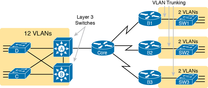
Figure 17-1 Layer 3 Switching at the Central Site
Figure 17-1 shows two switches, labeled A and B, which could act as Layer 3 switches—both with SVIs and routed interfaces. The figure shows a central site campus LAN on the left, with 12 VLANs. Switches A and B act as Layer 3 switches, combining the functions of a router and a switch, routing between all 12 subnets/VLANs, as well as routing to/from the Core router. Those Layer 3 switches could use SVIs, routed interfaces, or both.
Figure 17-1 also shows a classic case for using a router with a VLAN trunk. Sites like the remote sites on the right side of the figure may have a WAN-connected router and a LAN switch. These sites might use ROAS to take advantage of the router’s ability to route over an 802.1Q trunk.
Note that Figure 17-1 just shows an example. The engineer could use Layer 3 switching at each site or routers with VLAN trunking at each site.
Configuring ROAS
This next topic discusses how routers route packets to subnets associated with VLANs connected to a router 802.1Q trunk. That long description can be a bit of a chore to repeat each time someone wants to discuss this feature, so over time, the networking world has instead settled on a shorter and more interesting name for this feature: router-on-a-stick (ROAS).
ROAS uses router VLAN trunking configuration to give the router a logical router interface connected to each VLAN. Because the router then has an interface connected to each VLAN, the router can also be configured with an IP address in the subnet that exists on each VLAN.
Routers use subinterfaces as the means to have an interface connected to a VLAN. The router needs to have an IP address/mask associated with each VLAN on the trunk. However, the router has only one physical interface for the link connected to the trunk. Cisco solves this problem by creating multiple virtual router interfaces, one associated with each VLAN on that trunk (at least for each VLAN that you want the trunk to support). Cisco calls these virtual interfaces subinterfaces. The configuration can then include an ip address command for each subinterface.
Figure 17-2 shows the concept with Router B1, one of the branch routers from Figure 17-1. Because this router needs to route between only two VLANs, the figure also shows two subinterfaces, named G0/0.10 and G0/0.20, which create a new place in the configuration where the per-VLAN configuration settings can be made. The router treats frames tagged with VLAN 10 as if they came in or out of G0/0.10 and frames tagged with VLAN 20 as if they came in or out G0/0.20.
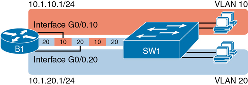
Figure 17-2 Subinterfaces on Router B1
In addition, note that most Cisco routers do not attempt to negotiate trunking, so both the router and switch need to manually configure trunking. This chapter discusses the router side of that trunking configuration; the matching switch interface would need to be configured with the switchport mode trunk command.
Example 17-1 shows a full example of the 802.1Q trunking configuration required on Router B1 in Figure 17-2. More generally, these steps detail how to configure 802.1Q trunking on a router:

Step 1. Use the interface type number.subint command in global configuration mode to create a unique subinterface for each VLAN that needs to be routed.
Step 2. Use the encapsulation dot1q vlan_id command in subinterface configuration mode to enable 802.1Q and associate one specific VLAN with the subinterface.
Step 3. Use the ip address address mask command in subinterface configuration mode to configure IP settings (address and mask).
Example 17-1 Router Configuration for the 802.1Q Encapsulation Shown in Figure 17-2
B1# show running-config
! Only pertinent lines shown
interface gigabitethernet 0/0
! No IP address up here! No encapsulation up here!
!
interface gigabitethernet 0/0.10
 encapsulation dot1q 10
 ip address 10.1.10.1 255.255.255.0
!
interface gigabitethernet 0/0.20
 encapsulation dot1q 20
 ip address 10.1.20.1 255.255.255.0
First, look at the subinterface numbers. The subinterface number begins with the period, like .10 and .20 in this case. These numbers can be any number from 1 up through a very large number (over 4 billion). The number just needs to be unique among all subinterfaces associated with this one physical interface. In fact, the subinterface number does not even have to match the associated VLAN ID. (The encapsulation command, and not the subinterface number, defines the VLAN ID associated with the subinterface.)
Note
Although not required, most sites do choose to make the subinterface number match the VLAN ID, as shown in Example 17-1, just to avoid confusion.
Each subinterface configuration lists two subcommands. One command (encapsulation) enables trunking and defines the VLAN whose frames are considered to be coming in and out of the subinterface. The ip address command works the same way it does on any other interface. Note that if the physical Ethernet interface reaches an up/up state, the subinterface should as well, which would then let the router add the connected routes shown at the bottom of the example.
Now that the router has a working interface, with IPv4 addresses configured, the router can route IPv4 packets on these subinterfaces. That is, the router treats these subinterfaces like any physical interface in terms of adding connected routes, matching those routes, and forwarding packets to/from those connected subnets.
The configuration and use of the native VLAN on the trunk require a little extra thought. The native VLAN can be configured on a subinterface, or on the physical interface, or ignored as in Example 17-1. Each 802.1Q trunk has one native VLAN, and if the router needs to route packets for a subnet that exists in the native VLAN, then the router needs some configuration to support that subnet. The two options to define a router interface for the native VLAN are

Configure the ip address command on the physical interface, but without an encapsulation command; the router considers this physical interface to be using the native VLAN.
Configure the ip address command on a subinterface and use the encapsulation dot1q vlan-id native subcommand to tell the router both the VLAN ID and the fact that it is the native VLAN.
Example 17-2 shows both native VLAN configuration options with a small change to the same configuration in Example 17-1. In this case, VLAN 10 becomes the native VLAN. The top part of the example shows the option to configure the router physical interface to use native VLAN 10. The second half of the example shows how to configure that same native VLAN on a subinterface. In both cases, the switch configuration also needs to be changed to make VLAN 10 the native VLAN.
Example 17-2 Router Configuration Using Native VLAN 10 on Router B1
! First option: put the native VLAN IP address on the physical interface
interface gigabitethernet 0/0
 ip address 10.1.10.1 255.255.255.0
!
interface gigabitethernet 0/0.20
 encapsulation dot1q 20
 ip address 10.1.20.1 255.255.255.0
! Second option: like Example 17-1, but add the native keyword
interface gigabitethernet 0/0.10
 encapsulation dot1q 10 native
 ip address 10.1.10.1 255.255.255.0
!
interface gigabitethernet 0/0.20
 encapsulation dot1q 20
 ip address 10.1.20.1 255.255.255.0
Verifying ROAS
Beyond using the show running-config command, ROAS configuration on a router can be best verified with two commands: show ip route [connected] and show vlans. As with any router interface, as long as the interface is in an up/up state and has an IPv4 address configured, IOS will put a connected (and local) route in the IPv4 routing table. So, a first and obvious check would be to see if all the expected connected routes exist. Example 17-3 lists the connected routes per the configuration shown in Example 17-1.
Example 17-3 Connected Routes Based on Example 17-1 Configuration
B1# show ip route connected
Codes: L - local, C - connected, S - static, R - RIP, M - mobile, B - BGP
! Legend omitted for brevity

      10.0.0.0/8 is variably subnetted, 4 subnets, 2 masks
C        10.1.10.0/24 is directly connected, GigabitEthernet0/0.10
L        10.1.10.1/32 is directly connected, GigabitEthernet0/0.10
C        10.1.20.0/24 is directly connected, GigabitEthernet0/0.20
L        10.1.20.1/32 is directly connected, GigabitEthernet0/0.20
As for interface and subinterface state, note that the ROAS subinterface state does depend to some degree on the physical interface state. In particular, the subinterface state cannot be better than the state of the matching physical interface. For instance, on Router B1 in the examples so far, physical interface G0/0 is in an up/up state, and the subinterfaces are in an up/up state. But if you unplugged the cable from that port, the physical port would fail to a down/down state, and the subinterfaces would also fail to a down/down state. Example 17-4 shows another example, with the physical interface being shut down, with the subinterfaces then automatically changed to an administratively down state as a result.
Example 17-4 Subinterface State Tied to Physical Interface State
B1# configure terminal
Enter configuration commands, one per line. End with CNTL/Z.
B1(config)# interface g0/0
B1(config-if)# shutdown
B1(config-if)# ^Z
B1# show ip interface brief | include 0/0
GigabitEthernet0/0         unassigned      YES manual administratively down down
GigabitEthernet0/0.10      10.1.10.1       YES manual administratively down down
GigabitEthernet0/0.20      10.1.20.1       YES manual administratively down down
Additionally, the subinterface state can also be enabled and disabled independently from the physical interface, using the no shutdown and shutdown commands in subinterface configuration mode.
Another useful ROAS verification command, show vlans, spells out which router trunk interfaces use which VLANs, which VLAN is the native VLAN, plus some packet statistics. The fact that the packet counters are increasing can be useful when verifying whether traffic is happening or not. Example 17-5 shows a sample, based on the Router B1 configuration in Example 17-2 (bottom half), in which native VLAN 10 is configured on subinterface G0/0.10. Note that the output identifies VLAN 1 associated with the physical interface, VLAN 10 as the native VLAN associated with G0/0.10, and VLAN 20 associated with G0/0.20. It also lists the IP addresses assigned to each interface/subinterface.
Example 17-5 Sample show vlans Command to Match Sample Router Trunking Configuration
R1# show vlans
Virtual LAN ID: 1 (IEEE 802.1Q Encapsulation)

   vLAN Trunk Interface: GigabitEthernet0/0

   Protocols Configured:  Address:        Received:    Transmitted:
        Other                                    0              83

   69 packets, 20914 bytes input
   147 packets, 11841 bytes output

Virtual LAN ID:   10 (IEEE 802.1Q Encapsulation)

    vLAN Trunk Interface:   GigabitEthernet0/0.10

 This is configured as native Vlan for the following interface(s) :
GigabitEthernet0/0      Native-vlan Tx-type: Untagged

      Protocols Configured:   Address:     Received:    Transmitted:
              IP              10.1.10.1           2               3
           Other                                  0               1

   3 packets, 722 bytes input
   4 packets, 264 bytes output

Virtual LAN ID:   20 (IEEE 802.1Q Encapsulation)

    vLAN Trunk Interface:   GigabitEthernet0/0.20

    Protocols Configured:  Address:        Received:  Transmitted:
            IP             10.1.20.1              0           134
         Other                                    0             1

    0 packets, 0 bytes input
    135 packets, 10498 bytes output
Troubleshooting ROAS
The biggest challenge when troubleshooting ROAS has to do with the fact that if you misconfigure only the router or misconfigure only the switch, the other device on the trunk has no way to know that the other side is misconfigured. That is, if you check the show ip route and show vlans commands on a router, and the output looks like it matches the intended configuration, and the connected routes for the correct subinterfaces show up, routing may still fail because of problems on the attached switch. So, troubleshooting ROAS often begins with checking the configuration on both the router and switch because there is no status output on either device that tells you where the problem might be.
First, to check ROAS on the router, you need to start with the intended configuration and ask questions about the configuration:
Is each non-native VLAN configured on the router with an encapsulation dot1q vlan-id command on a subinterface?
Do those same VLANs exist on the trunk on the neighboring switch (show interfaces trunk), and are they in the allowed list, not VTP pruned, and not STP blocked?
Does each router ROAS subinterface have an IP address/mask configured per the planned configuration?
If using the native VLAN, is it configured correctly on the router either on a subinterface (with an encapsulation dot1q vlan-id native command) or implied on the physical interface?
Is the same native VLAN configured on the neighboring switch’s trunk in comparison to the native VLAN configured on the router?
Are the router physical or ROAS subinterfaces configured with a shutdown command?
For some of these steps, you need to be ready to investigate possible VLAN trunking issues on the LAN switch. The reason is that on many Cisco routers, router interfaces do not negotiate trunking. As a result, ROAS relies on static trunk configuration on both the router and switch. If the switch has any problems with VLANs or the VLAN trunking configuration on its side of the trunk, the router has no way to realize that the problem exists.
For example, imagine you configured ROAS on a router just like in Example 17-1 or Example 17-2. However, the switch on the other end of the link had no matching configuration. For instance, maybe the switch did not even define VLANs 10 and 20. Maybe the switch did not configure trunking on the port connected to the router. Even with blatant misconfiguration or missing configuration on the switch, the router still shows up/up ROAS interfaces and subinterfaces, IP routes in the output of show ip route, and meaningful configuration information in the output of the show vlans command.
VLAN Routing with Layer 3 Switch SVIs
Using a router with ROAS to route packets makes sense in some cases, particularly at small remote sites. In sites with a larger LAN, network designers choose to use Layer 3 switches for most inter-VLAN routing.
A Layer 3 switch (also called a multilayer switch) is one device, but it executes logic at two layers: Layer 2 LAN switching and Layer 3 IP routing. The Layer 2 switch function forwards frames inside each VLAN, but it will not forward frames between VLANs. The Layer 3 forwarding (routing) logic forwards IP packets between VLANs.
Layer 3 switches typically support two configuration options to enable IPv4 routing inside the switch, specifically to enable IPv4 on switch interfaces. This section explains one option, an option that uses switched virtual interfaces (SVI). The final major section of the chapter deals with the other option for configuring IPv4 addresses on Layer 3 switches: routed interfaces.
Configuring Routing Using Switch SVIs
The configuration of a Layer 3 switch mostly looks like the Layer 2 switching configuration shown back in Parts II and III of this book, with a small bit of configuration added for the Layer 3 functions. The Layer 3 switching function needs a virtual interface connected to each VLAN internal to the switch. These VLAN interfaces act like router interfaces, with an IP address and mask. The Layer 3 switch has an IP routing table, with connected routes off each of these VLAN interfaces. (These interfaces are also referred to as switched virtual interfaces [SVI].)
To show the concept of Layer 3 switching with SVIs, the following example uses the same branch office with two VLANs shown in the earlier examples, but now the design will use Layer 3 switching in the LAN switch. Figure 17-3 shows the design changes and configuration concept for the Layer 3 switch function with a router icon inside the switch, to emphasize that the switch routes the packets.
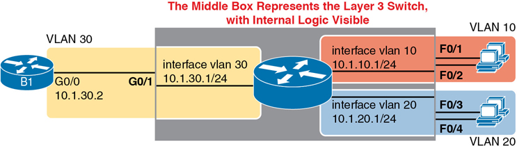
Figure 17-3 Routing on VLAN Interfaces in a Layer 3 Switch
Note that the figure represents the internals of the Layer 3 switch within the box in the middle of the figure. The branch still has two user VLANs (10 and 20), so the Layer 3 switch needs one VLAN interface for each VLAN. The figure shows a router icon inside the gray box to represent the Layer 3 switching function, with two VLAN interfaces on the right side of that icon. In addition, the traffic still needs to get to router B1 (a physical router) to access the WAN, so the switch uses a third VLAN (VLAN 30 in this case) for the link to Router B1. The physical link between the Layer 3 switch and router B1 would not be a trunk, but instead be an access link.
The following steps show how to configure Layer 3 switching using SVIs. Note that on some switches, like the 2960 and 2960-XR switches used for the examples in this book, the ability to route IPv4 packets must be enabled first, with a reload of the switch required to enable the feature. The steps that occur after the reload would apply to all models of Cisco switches that are capable of doing Layer 3 switching.
Step 1. Enable IP routing on the switch, as needed:
A. Use the sdm prefer lanbase-routing command (or similar) in global configuration mode to change the switch forwarding ASIC settings to make space for IPv4 routes at the next reload of the switch.
B. Use the reload EXEC command in enable mode to reload (reboot) the switch to pick up the new sdm prefer command setting.
C. Once reloaded, use the ip routing command in global configuration mode to enable the IPv4 routing function in IOS software and to enable key commands like show ip route.
Step 2. Configure each SVI interface, one per VLAN for which routing should be done by this Layer 3 switch:
A. Use the interface vlan vlan_id command in global configuration mode to create a VLAN interface and to give the switch’s routing logic a Layer 3 interface connected into the VLAN of the same number.
B. Use the ip address address mask command in VLAN interface configuration mode to configure an IP address and mask on the VLAN interface, enabling IPv4 routing on that VLAN interface.
C. (As needed) Use the no shutdown command in interface configuration mode to enable the VLAN interface (if it is currently in a shutdown state).
Example 17-6 shows the configuration to match Figure 17-3. In this case, switch SW1 has already used the sdm prefer global command to change to a setting that supports IPv4 routing, and the switch has been reloaded. The example shows the related configuration on all three VLAN interfaces.
Example 17-6 VLAN Interface Configuration for Layer 3 Switching
ip routing
!
interface vlan 10
 ip address 10.1.10.1 255.255.255.0
!
interface vlan 20
 ip address 10.1.20.1 255.255.255.0
!
interface vlan 30
 ip address 10.1.30.1 255.255.255.0
Verifying Routing with SVIs
With the VLAN configuration shown in the previous section, the switch is ready to route packets between the VLANs as shown in Figure 17-3. To support the routing of packets, the switch adds connected IP routes as shown in Example 17-7; note that each route is listed as being connected to a different VLAN interface.
Example 17-7 Connected Routes on a Layer 3 Switch
SW1# show ip route
! legend omitted for brevity

       10.0.0.0/8 is variably subnetted, 6 subnets, 2 masks
C         10.1.10.0/24 is directly connected, Vlan10
L         10.1.10.1/32 is directly connected, Vlan10
C         10.1.20.0/24 is directly connected, Vlan20
L         10.1.20.1/32 is directly connected, Vlan20
C         10.1.30.0/24 is directly connected, Vlan30
L         10.1.30.1/32 is directly connected, Vlan30
The switch would also need additional routes to the rest of the network (not shown in the figures in this chapter). The Layer 3 switch could use static routes or a routing protocol, depending on the capabilities of the switch. For instance, if you then enabled OSPF on the Layer 3 switch, the configuration and verification would work the same as it does on a router, as discussed in Chapter 20, “Implementing OSPF.” The routes that IOS adds to the Layer 3 switch’s IP routing table would list the VLAN interfaces as outgoing interfaces.
Note
Some models of Cisco enterprise switches, based on model, IOS version, and IOS feature set, support different capabilities for IP routing and routing protocols, so for real networks, check the capabilities of the switch model by browsing at Cisco.com. In particular, check the Cisco Feature Navigator (CFN) tool at http://www.cisco.com/go/cfn.
Troubleshooting Routing with SVIs
There are two big topics to investigate when troubleshooting routing over LANs with SVIs. First, you have to make sure the switch has been enabled to support IP routing. Second, the VLAN associated with each VLAN interface must be known and active on the local switch; otherwise, the VLAN interfaces do not come up.
First, about enabling IP routing, note that some models of Cisco switches default to enable Layer 3 switching, and some do not. So, to make sure your switch supports Layer 3 routing, look to those first few configuration commands listed in the configuration checklist found in the earlier section “Configuring Routing Using Switch SVIs.” Those commands are sdm prefer (followed by a reload) and then ip routing (after the reload).
The sdm prefer command changes how the switch forwarding chips allocate memory for different forwarding tables, and changes to those tables require a reload of the switch. By default, many access switches that support Layer 3 switching still have an SDM default that does not allocate space for an IP routing table. Once changed and reloaded, the ip routing command then enables IPv4 routing in IOS software. Both are necessary before some Cisco switches will act as a Layer 3 switch.
Example 17-8 shows some symptoms on a router for which Layer 3 switching had not yet been enabled by the sdm prefer command. As you can see, both the show ip route EXEC command and the ip routing config command are rejected because they do not exist to IOS until the sdm prefer command has been used (followed by a reload of the switch).
Example 17-8 Evidence That a Switch Has Not Yet Enabled IPv4 Routing
SW1# show ip route
             ^

% Invalid input detected at '^' marker.

SW3# configure terminal
Enter configuration commands, one per line. End with CNTL/Z.
SW3(config)# ip routing
                ^

% Invalid input detected at '^' marker.
The second big area to investigate when troubleshooting SVIs relates to the SVI state, a state that ties to the state of the associated VLANs. Each VLAN interface has a matching VLAN of the same number, and the VLAN interface’s state is tied to the state of the VLAN in certain ways. In particular, for a VLAN interface to be in an up/up state:
Step 1. The VLAN must be defined on the local switch (either explicitly or learned with VTP).
Step 2. The switch must have at least one up/up interface using the VLAN, either/both:
A. An up/up access interface assigned to that VLAN
B. A trunk interface for which the VLAN is in the allowed list, is STP forwarding, and is not VTP pruned
Step 3. The VLAN (not the VLAN interface) must be administratively enabled (that is, not shutdown).
Step 4. The VLAN interface (not the VLAN) must be administratively enabled (that is, not shutdown).
When working through the steps in the list, keep in mind that the VLAN and the VLAN interface are related but separate ideas, and the configuration items are separate in the CLI. The VLAN interface is a switch’s Layer 3 interface connected to the VLAN. If you want to route packets for the subnets on VLANs 11, 12, and 13, the matching VLAN interfaces must be numbered 11, 12, and 13. And both the VLANs and the VLAN interfaces can be disabled and enabled with the shutdown and no shutdown commands (as mentioned in Steps 3 and 4 in the previous list), so you have to check for both.
Example 17-9 shows three scenarios, each of which leads to one of the VLAN interfaces in the previous configuration example (Figure 17-3, Example 17-6) to fail. At the beginning of the example, all three VLAN interfaces are up/up. VLANs 10, 20, and 30 each have at least one access interface up and working. The example works through three scenarios:
Scenario 1: The last access interface in VLAN 10 is shut down (F0/1), so IOS shuts down the VLAN 10 interface.
Scenario 2: VLAN 20 (not VLAN interface 20, but VLAN 20) is deleted, which results in IOS then bringing down (not shutting down) the VLAN 20 interface.
Scenario 3: VLAN 30 (not VLAN interface 30, but VLAN 30) is shut down, which results in IOS then bringing down (not shutting down) the VLAN 30 interface.
Example 17-9 Three Examples That Cause VLAN Interfaces to Fail
SW1# show interfaces status
! Only ports related to the example are shown
Port      Name               Status       Vlan       Duplex  Speed Type
Fa0/1                        connected    10         a-full  a-100 10/100BaseTX
Fa0/2                        notconnect   10           auto   auto 10/100BaseTX
Fa0/3                        connected    20         a-full  a-100 10/100BaseTX
Fa0/4                        connected    20         a-full  a-100 10/100BaseTX
Gi0/1                        connected    30         a-full a-1000 10/100/1000BaseTX
SW1# configure terminal
Enter configuration commands, one per line. End with CNTL/Z.

! Case 1: Interface F0/1, the last up/up access interface in VLAN 10, is shutdown
SW1(config)# interface fastEthernet 0/1
SW1(config-if)# shutdown
SW1(config-if)#
*Apr 2 19:54:08.784: %LINEPROTO-5-UPDOWN: Line protocol on Interface Vlan10, changed
state to down
SW1(config-if)#
*Apr 2 19:54:10.772: %LINK-5-CHANGED: Interface FastEthernet0/1, changed state to
administratively down
*Apr 2 19:54:11.779: %LINEPROTO-5-UPDOWN: Line protocol on Interface FastEthernet0/1,
changed state to down

! Case 2: VLAN 20 is deleted
SW1(config)# no vlan 20
SW1(config)#
*Apr 2 19:54:39.688: %LINEPROTO-5-UPDOWN: Line protocol on Interface Vlan20, changed
state to down

! Case 3: VLAN 30, the VLAN from the switch to the router, is shutdown
SW1(config)# vlan 30
SW1(config-vlan)# shutdown
SW1(config-vlan)# exit
SW1(config)#
*Apr 2 19:55:25.204: %LINEPROTO-5-UPDOWN: Line protocol on Interface Vlan30, changed
state to down

! Final status of all three VLAN interfaces are below
SW1# show ip interface brief | include Vlan
Vlan1                  unassigned      YES manual administratively down down
Vlan10                 10.1.10.1       YES manual up                    down
Vlan20                 10.1.20.1       YES manual up                    down
Vlan30                 10.1.30.1       YES manual up                    down
Note that the example ends with the three VLAN interfaces in an up/down state per the show ip interface brief command.
VLAN Routing with Layer 3 Switch Routed Ports
When Layer 3 switches use SVIs, the physical interfaces on the switches act like they always have: as Layer 2 interfaces. That is, the physical interfaces receive Ethernet frames. The switch learns the source MAC address of the frame, and the switch forwards the frame based on the destination MAC address. To perform routing, any Ethernet frames destined for any of the SVI interface MAC addresses trigger the processing of the Layer 2 switching logic, resulting in normal routing actions like stripping data-link headers, making a routing decision, and so on.
Alternately, the Layer 3 switch configuration can make a physical port act like a router interface instead of a switch interface. To do so, the switch configuration makes that port a routed port. On a routed port, the switch does not perform Layer 2 switching logic on that frame. Instead, frames arriving in a routed port trigger the Layer 3 routing logic, including
Stripping off the incoming frame’s Ethernet data-link header/trailer
Making a Layer 3 forwarding decision by comparing the destination IP address to the IP routing table
Adding a new Ethernet data-link header/trailer to the packet
Forwarding the packet, encapsulated in a new frame
This third major section of the chapter examines routed interfaces as configured on Cisco Layer 3 switches, but with a particular goal in mind: to also discuss Layer 3 EtherChannels. The exam topics do not mention routed interfaces specifically, but the exam topics do mention L3 EtherChannels, meaning Layer 3 EtherChannels.
You might recall that Chapter 10, “RSTP and EtherChannel Configuration,” discussed Layer 2 EtherChannels. Like Layer 2 EtherChannels, Layer 3 EtherChannels also treat multiple links as one link. Unlike Layer 2 EtherChannels, however, Layer 3 EtherChannels treat the channel as a routed port instead of switched port. So this section first looks at routed ports on Cisco Layer 3 switches and then discusses Layer 3 EtherChannels.
Implementing Routed Interfaces on Switches
When a Layer 3 switch needs a Layer 3 interface connected to a subnet, and only one physical interface connects to that subnet, the network engineer can choose to use a routed port instead of an SVI. Conversely, when the Layer 3 switch needs a Layer 3 interface connected to a subnet, and many physical interfaces on the switch connect to that subnet, an SVI needs to be used. (SVIs forward traffic internally into the VLAN, so that then the Layer 2 logic can forward the frame out any of the ports in the VLAN. Routed ports cannot.)
To see why, consider the design in Figure 17-4, which repeats the same design from Figure 17-3 (used in the SVI examples). In that design, the gray rectangle on the right represents the switch and its internals. On the right of the switch, at least two access ports sit in both VLAN 10 and VLAN 20. However, that figure shows a single link from the switch to Router B1. The switch could configure the port as an access port in a separate VLAN, as shown with VLAN 30 in Examples 17-6 and 17-7. However, with only one switch port needed, the switch could configure that link as a routed port, as shown in the figure.
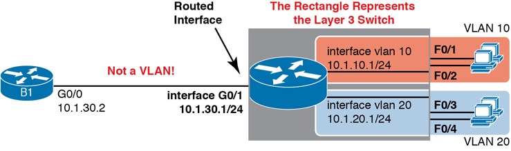
Figure 17-4 Routing on a Routed Interface on a Switch
Enabling a switch interface to be a routed interface instead of a switched interface is simple: just use the no switchport subcommand on the physical interface. Cisco switches capable of being a Layer 3 switch use a default of the switchport command to each switch physical interface. Think about the word switchport for a moment. With that term, Cisco tells the switch to treat the port like it is a port on a switch—that is, a Layer 2 port on a switch. To make the port stop acting like a switch port and instead act like a router port, use the no switchport command on the interface.
Once the port is acting as a routed port, think of it like a router interface. That is, configure the IP address on the physical port, as implied in Figure 17-4. Example 17-10 shows a completed configuration for the interfaces configured on the switch in Figure 17-4. Note that the design uses the exact same IP subnets as the example that showed SVI configuration in Example 17-6, but now, the port connected to subnet 10.1.30.0 has been converted to a routed port. All you have to do is add the no switchport command to the physical interface and configure the IP address on the physical interface.
Example 17-10 Configuring Interface G0/1 on Switch SW1 as a Routed Port
ip routing
!
interface vlan 10
 ip address 10.1.10.1 255.255.255.0
!
interface vlan 20
 ip address 10.1.20.1 255.255.255.0
!
interface gigabitethernet 0/1
 no switchport
 ip address 10.1.30.1 255.255.255.0
Once configured, the routed interface will show up differently in command output in the switch. In particular, for an interface configured as a routed port with an IP address, like interface GigabitEthernet0/1 in the previous example:
show interfaces: Similar to the same command on a router, the output will display the IP address of the interface. (Conversely, for switch ports, this command does not list an IP address.)
show interfaces status: Under the “VLAN” heading, instead of listing the access VLAN or the word trunk, the output lists the word routed, meaning that it is a routed port.
show ip route: Lists the routed port as an outgoing interface in routes.
show interfaces type number switchport: If a routed port, the output is short and confirms that the port is not a switch port. (If the port is a Layer 2 port, this command lists many configuration and status details.)
Example 17-11 shows samples of all four of these commands as taken from the switch as configured in Example 17-10.
Example 17-11 Verification Commands for Routed Ports on Switches
SW11# show interfaces g0/1
GigabitEthernet0/1 is up, line protocol is up (connected)
 Hardware is Gigabit Ethernet, address is bcc4.938b.e541 (bia bcc4.938b.e541)
 Internet address is 10.1.30.1/24
! lines omitted for brevity

SW1# show interfaces status
! Only ports related to the example are shown; the command lists physical only
Port      Name               Status       Vlan       Duplex  Speed Type
Fa0/1                        connected    10         a-full  a-100 10/100BaseTX
Fa0/2                        notconnect   10           auto   auto 10/100BaseTX
Fa0/3                        connected    20         a-full  a-100 10/100BaseTX
Fa0/4                        connected    20         a-full  a-100 10/100BaseTX
Gi0/1                        connected    routed     a-full a-1000 10/100/1000BaseTX

SW1# show ip route
! legend omitted for brevity

       10.0.0.0/8 is variably subnetted, 6 subnets, 2 masks
C         10.1.10.0/24 is directly connected, Vlan10
L         10.1.10.1/32 is directly connected, Vlan10
C         10.1.20.0/24 is directly connected, Vlan20
L         10.1.20.1/32 is directly connected, Vlan20
C         10.1.30.0/24 is directly connected, GigabitEthernet0/1
L         10.1.30.1/32 is directly connected, GigabitEthernet0/1

SW1# show interfaces g0/1 switchport
Name: Gi0/1
Switchport: Disabled
So, with two options—SVI and routed ports—where should you use each?
For any topologies with a point-to-point link between two devices that do routing, a routed interface works well.
Figure 17-5 shows an example of where to use SVIs and where to use routed ports in a typical core/distribution/access design. In this design, the core (Core1, Core2) and distribution (D11 through D14) switches perform Layer 3 switching. All the ports that are links directly between the Layer 3 switches can be routed interfaces. For VLANs for which many interfaces (access and trunk) connect to the VLAN, SVIs make sense because the SVIs can send and receive traffic out multiple ports on the same switch. In this design, all the ports on Core1 and Core2 will be routed ports, while the four distribution switches will use some routed ports and some SVIs.

Figure 17-5 Using Routed Interfaces for Core and Distribution Layer 3 Links
Implementing Layer 3 EtherChannels
So far, this section has stated that routed interfaces can be used with a single point-to-point link between pairs of Layer 3 switches, or between a Layer 3 switch and a router. However, in most designs, the network engineers use at least two links between each pair of distribution and core switches, as shown in Figure 17-6.
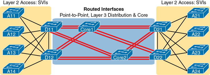
Figure 17-6 Two Links Between Each Distribution and Core Switch
While each individual port in the distribution and core could be treated as a separate routed port, it is better to combine each pair of parallel links into a Layer 3 EtherChannel. Without using EtherChannel, you can still make each port on each switch in the center of the figure be a routed port. It works. However, once you enable a routing protocol but don’t use EtherChannels, each Layer 3 switch will now learn two IP routes with the same neighboring switch as the next hop—one route over one link, another route over the other link.
Using a Layer 3 EtherChannel makes more sense with multiple parallel links between two switches. By doing so, each pair of links acts as one Layer 3 link. So, each pair of switches has one routing protocol neighbor relationship with the neighbor, and not two. Each switch learns one route per destination per pair of links, and not two. IOS then balances the traffic, often with better balancing than the balancing that occurs with the use of multiple IP routes to the same subnet. Overall, the Layer 3 EtherChannel approach works much better than leaving each link as a separate routed port and using Layer 3 balancing.
Compared to what you have already learned, configuring a Layer 3 EtherChannel takes only a little more work. Chapter 10 already showed you how to configure an EtherChannel. This chapter has already shown how to make a port a Layer 3 routed port. Next, you have to combine the two ideas by combining both the EtherChannel and routed port configuration. The following checklist shows the steps, assuming a static definition.
Step 1. Configure the physical interfaces as follows, in interface configuration mode:
A. Add the channel-group number mode on command to add it to the channel. Use the same number for all physical interfaces on the same switch, but the number used (the channel-group number) can differ on the two neighboring switches.
B. Add the no switchport command to make each physical port a routed port.
Step 2. Configure the PortChannel interface:
A. Use the interface port-channel number command to move to port-channel configuration mode for the same channel number configured on the physical interfaces.
B. Add the no switchport command to make sure that the port-channel interface acts as a routed port. (IOS may have already added this command.)
C. Use the ip address address mask command to configure the address and mask.
Note
Cisco uses the term EtherChannel in concepts discussed in this section and then uses the term PortChannel, with command keyword port-channel, when verifying and configuring EtherChannels. For the purposes of understanding the technology, you may treat these terms as synonyms. However, it helps to pay close attention to the use of the terms PortChannel and EtherChannel as you work through the examples in this section because IOS uses both.
Example 17-12 shows an example of the configuration for a Layer 3 EtherChannel for switch SW1 in Figure 17-7. The EtherChannel defines port-channel interface 12 and uses subnet 10.1.12.0/24.
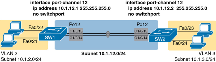
Figure 17-7 Design Used in EtherChannel Configuration Examples
Example 17-12 Layer 3 EtherChannel Configuration on Switch SW1
interface GigabitEthernet1/0/13
 no switchport
 no ip address
 channel-group 12 mode on
!
interface GigabitEthernet1/0/14
 no switchport
 no ip address
 channel-group 12 mode on
!
interface Port-channel12
 no switchport
 ip address 10.1.12.1 255.255.255.0
Of particular importance, note that although the physical interfaces and PortChannel interface are all routed ports, the IP address should be placed on the PortChannel interface only. In fact, when the no switchport command is configured on an interface, IOS adds the no ip address command to the interface. Then configure the IP address on the PortChannel interface only.
Once configured, the PortChannel interface appears in several commands, as shown in Example 17-13. The commands that list IP addresses and routes refer to the PortChannel interface. Also, note that the show interfaces status command lists the fact that the physical ports and the port-channel 12 interface are all routed ports.
Example 17-13 Verification Commands Listing Interface Port-Channel 12 from Switch SW1
SW1# show interfaces port-channel 12
Port-channel12 is up, line protocol is up (connected)
  Hardware is EtherChannel, address is bcc4.938b.e543 (bia bcc4.938b.e543)
  Internet address is 10.1.12.1/24
! lines omitted for brevity

SW1# show interfaces status
! Only ports related to the example are shown.
Port      Name               Status      Vlan       Duplex  Speed Type
Gi1/0/13                     connected   routed     a-full a-1000 10/100/1000BaseTX
Gi1/0/14                     connected   routed     a-full a-1000 10/100/1000BaseTX
Po12                         connected   routed     a-full a-1000

SW1# show ip route
! legend omitted for brevity
       10.0.0.0/8 is variably subnetted, 4 subnets, 2 masks
C         10.1.2.0/24 is directly connected, Vlan2
L         10.1.2.1/32 is directly connected, Vlan2
C         10.1.12.0/24 is directly connected, Port-channel12
L         10.1.12.1/32 is directly connected, Port-channel12
For a final bit of verification, you can examine the EtherChannel directly with the show etherchannel summary command as listed in Example 17-14. Note in particular that it lists a flag legend for characters that identify key operational states, such as whether a port is bundled (included) in the PortChannel (P) and whether it is acting as a routed (R) or switched (S) port.
Example 17-14 Verifying the EtherChannel
SW1# show etherchannel 12 summary
Flags: D - down        P - bundled in port-channel
       I - stand-alone s - suspended
       H - Hot-standby (LACP only)
       R - Layer3      S - Layer2
       U - in use      f - failed to allocate aggregator

       M - not in use, minimum links not met
       u - unsuitable for bundling
       w - waiting to be aggregated
       d - default port


Number of channel-groups in use: 1
Number of aggregators:           1

Group  Port-channel  Protocol    Ports
------+-------------+-----------+-----------------------------------------------
12     Po12(RU)         -        Gi1/0/13(P) Gi1/0/14(P)
Troubleshooting Layer 3 EtherChannels
When you are troubleshooting a Layer 3 EtherChannel, there are two main areas to consider. First, you need to look at the configuration of the channel-group command, which enables an interface for an EtherChannel. Second, you should check a list of settings that must match on the interfaces for a Layer 3 EtherChannel to work correctly.
As for the channel-group interface subcommand, this command can enable EtherChannel statically or dynamically. If dynamic, this command’s keywords imply either Port Aggregation Protocol (PaGP) or Link Aggregation Control Protocol (LACP) as the protocol to negotiate between the neighboring switches whether they put the link into the EtherChannel.
If all this sounds vaguely familiar, it is the exact same configuration covered way back in the Chapter 10 section “Configuring Dynamic EtherChannels.” The configuration of the channel-group subcommand is exactly the same, with the same requirements, whether configuring Layer 2 or Layer 3 EtherChannels. So, it might be a good time to review those EtherChannel configuration details from Chapter 10. However, regardless of when you review and master those commands, note that the configuration of the EtherChannel (with the channel-group subcommand) is the same, whether Layer 2 or Layer 3.
Additionally, you must do more than just configure the channel-group command correctly for all the physical ports to be bundled into the EtherChannel. Layer 2 EtherChannels have a longer list of requirements, but Layer 3 EtherChannels also require a few consistency checks between the ports before they can be added to the EtherChannel. The following is the list of requirements for Layer 3 EtherChannels:
no switchport: The PortChannel interface must be configured with the no switchport command, and so must the physical interfaces. If a physical interface is not also configured with the no switchport command, it will not become operational in the EtherChannel.
Speed: The physical ports in the channel must use the same speed.
duplex: The physical ports in the channel must use the same duplex.
Chapter Review
One key to doing well on the exams is to perform repetitive spaced review sessions. Review this chapter’s material using either the tools in the book or interactive tools for the same material found on the book’s companion website. Refer to the “Your Study Plan” element for more details. Table 17-2 outlines the key review elements and where you can find them. To better track your study progress, record when you completed these activities in the second column.
Table 17-2 Chapter Review Tracking
Review Element |
Review Date(s) |
Resource Used |
|---|---|---|
Review key topics |
|
Book, website |
Review key terms |
|
Book, website |
Repeat DIKTA questions |
|
Book, PTP |
Review config checklists |
|
Book, website |
Review command tables |
|
Book |
Do labs |
|
Blog |
Watch video |
|
Website |
Review All the Key Topics
Table 17-3 Key Topics for Chapter 17
Key Topic Element |
Description |
Page Number |
|---|---|---|
Concept of VLAN subinterfaces on a router |
396 |
|
List |
Two alternative methods to configure the native VLAN in a ROAS configuration |
398 |
List |
Troubleshooting suggestions for ROAS configuration |
401 |
Layer 3 switching with SVIs concept and configuration |
402 |
|
List |
Troubleshooting suggestions for correct operation of a Layer 3 switch that uses SVIs |
405 |
Layer 3 switching with routed ports concept and configuration |
407 |
|
List |
show commands that list Layer 3 routed ports in their output |
408 |
Layer 3 EtherChannel concept and configuration |
411 |
|
List |
List of configuration settings that must be consistent before IOS will bundle a link with an existing Layer 3 EtherChannel |
414 |
Key Terms You Should Know
switched virtual interface (SVI)
Command References
Tables 17-4 and 17-5 list configuration and verification commands used in this chapter. As an easy review exercise, cover the left column in a table, read the right column, and try to recall the command without looking. Then repeat the exercise, covering the right column, and try to recall what the command does.
Table 17-4 Chapter 17 Configuration Command Reference
Command |
Description |
|---|---|
interface type number.subint |
Router global command to create a subinterface and to enter configuration mode for that subinterface |
encapsulation dot1q vlan-id [native] |
Router subinterface subcommand that tells the router to use 802.1Q trunking, for a particular VLAN, and with the native keyword, to not encapsulate in a trunking header |
[no] ip routing |
Global command that enables (ip routing) or disables (no ip routing) the routing of IPv4 packets on a router or Layer 3 switch |
interface vlan vlan-id |
A switch global command on a Layer 3 switch to create a VLAN interface and to enter configuration mode for that VLAN interface |
sdm prefer lanbase-routing |
Command on some Cisco switches that reallocates forwarding chip memory to allow for an IPv4 routing table |
[no] switchport |
Layer 3 switch subcommand that makes the port act as a Layer 2 port (switchport) or Layer 3 routed port (no switchport) |
interface port-channel channel-number |
A switch command to enter PortChannel configuration mode and also to create the PortChannel if not already created |
channel-group channel-number mode {auto | desirable | active | passive | on} |
Interface subcommand that enables EtherChannel on the interface |
Table 17-5 Chapter 17 EXEC Command Reference
Command |
Description |
|---|---|
show ip route |
Lists the router’s entire routing table |
show ip route [connected] |
Lists a subset of the IP routing table |
show vlans |
Lists VLAN configuration and statistics for VLAN trunks configured on routers |
show interfaces [interface type number] |
Lists detailed status and statistical information, including IP address and mask, about all interfaces (or the listed interface only) |
show interfaces [interface type number] status |
Among other facts, for switch ports, lists the access VLAN or the fact that the interface is a trunk; or, for routed ports, lists “routed” |
show interfaces interface-id switchport |
For switch ports, lists information about any interface regarding administrative settings and operational state; for routed ports, the output simply confirms the port is a routed (not switched) port |
show interfaces vlan number |
Lists the interface status, the switch’s IPv4 address and mask, and much more |
show etherchannel [channel-group-number] summary |
Lists information about the state of EtherChannels on this switch, including whether the channel is a Layer 2 or Layer 3 EtherChannel |